Attached files
| file | filename |
|---|---|
| EX-32.2 - EX-32.2 - CHUGACH ELECTRIC ASSOCIATION INC | c004-20150930xex322.htm |
| EX-31.2 - EX-31.2 - CHUGACH ELECTRIC ASSOCIATION INC | c004-20150930xex312.htm |
| EX-10.75.3 - EX-10.75.3 - CHUGACH ELECTRIC ASSOCIATION INC | c004-20150930ex10753df28.htm |
| EX-31.1 - EX-31.1 - CHUGACH ELECTRIC ASSOCIATION INC | c004-20150930xex311.htm |
| EX-32.1 - EX-32.1 - CHUGACH ELECTRIC ASSOCIATION INC | c004-20150930xex321.htm |
| 10-Q - 10-Q - CHUGACH ELECTRIC ASSOCIATION INC | c004-20150930x10q.htm |
EXECUTION VERSION
CONTRACT NUMBER 51008
SOUTHCENTRAL POWER
PROJECT
ENGINEERING, PROCUREMENT
AND CONSTRUCTION CONTRACT
EXECUTION VERSION
CONTRACT NUMBER 51008
ENGINEERING, PROCUREMENT AND CONSTRUCTION CONTRACT
dated as of June 18, 2010
by and between
Chugach Electric Association, Inc.,
as Company
and
SNC-Lavalin Constructors, Inc.,
as Contractor
EXECUTION VERSION
CONTRACT NUMBER 51008
TABLE OF CONTENTS
|
ARTICLE 1 DEFINITIONS AND INTERPRETATION |
1 | |||||
|
Section 1.1 |
Defined Terms |
1 | ||||
|
Section 1.2 |
Interpretation |
2 | ||||
|
ARTICLE 2 PROJECT COMMENCEMENT AND COMPLETION |
2 | |||||
|
Section 2.1 |
Full Notice to Proceed |
2 | ||||
|
ARTICLE 3 CONSIDERATION AND PAYMENT |
4 | |||||
|
Section 3.1 |
Contract Price; Payment Milestones and Effect of Payment on Title Transfer |
4 | ||||
|
Section 3.2 |
Conditions Precedent to Payment of Invoiced Amounts |
5 | ||||
|
Section 3.3 |
Wire Transfer |
6 | ||||
|
Section 3.4 |
Invoice Instructions |
6 | ||||
|
Section 3.5 |
Contractor Taxes |
7 | ||||
|
Section 3.6 |
Project Taxes |
7 | ||||
|
Section 3.7 |
Offset and Withholding Provisions |
8 | ||||
|
Section 3.8 |
Payment Lien and Claim Releases |
8 | ||||
|
Section 3.9 |
Basis of Contract Price |
8 | ||||
|
ARTICLE 4 REPRESENTATIONS AND WARRANTIES OF CONTRACTOR |
9 | |||||
|
Section 4.1 |
Organization, Good Standing and Power |
10 | ||||
|
Section 4.2 |
Authority; Execution and Delivery: Enforceability |
10 | ||||
|
Section 4.3 |
Validity of Contract; No Conflict |
10 | ||||
|
Section 4.4 |
Governmental Approvals and Consents |
11 | ||||
|
Section 4.5 |
No Proceedings |
11 | ||||
|
Section 4.6 |
Compliance |
11 | ||||
|
Section 4.7 |
Environmental Matters |
12 | ||||
|
Section 4.8 |
No Defaults |
12 | ||||
|
Section 4.9 |
Expertise |
12 | ||||
|
ARTICLE 4 REPRESENTATIONS AND WARRANTIES OF COMPANY |
13 | |||||
|
Section 5.1 |
Corporate Organization |
13 | ||||
|
Section 5.2 |
Validity of Contract; No Conflict |
13 | ||||
|
Section 5.3 |
Approvals and Authorizations |
14 | ||||
|
Section 5.4 |
Company-Procured Equipment |
14 | ||||
|
Section 5.5 |
No Proceedings |
14 | ||||
|
ARTICLE 6 CONTRACTOR’S SECURITY |
14 | |||||
|
Section 6.1 |
Contractor’s Parent Company Guaranty and Letter of Credit |
14 | ||||
|
ARTICLE 7 GENERAL OBLIGATIONS OF CONTRACTOR |
15 | |||||
|
Section 7.1 |
Contractor’s General Obligations |
15 | ||||
|
Section 7.2 |
Physical Obstructions and Conditions |
17 | ||||
|
Section 7.3 |
Selection of Suppliers and Use of Subcontractors |
17 | ||||
|
Section 7.4 |
Compliance with Applicable Law |
18 | ||||
1
EXECUTION VERSION
CONTRACT NUMBER 51008
|
Section 7.5 |
Governmental Approvals |
18 | |||||||
|
Section 7.6 |
Other Contractors |
18 | |||||||
|
Section 7.7 |
Construction Coordination |
19 | |||||||
|
Section 7.8 |
Authority For Access for Inspection |
21 | |||||||
|
Section 7.9 |
Training |
21 | |||||||
|
Section 7.10 |
Safety |
22 | |||||||
|
Section 7.11 |
Intellectual Property Rights and Computer Program Licenses |
22 | |||||||
|
Section 7.12 |
Contractor’s Representatives |
23 | |||||||
|
Section 7.13 |
Contractor’s and Subcontractor’s Personnel |
24 | |||||||
|
Section 7.14 |
Use of Premises and Trespassing |
24 | |||||||
|
Section 7.15 |
Temporary Facilities |
25 | |||||||
|
Section 7.16 |
Contractor Deliverables |
25 | |||||||
|
Section 7.17 |
Cooperation Between the Parties |
25 | |||||||
|
Section 7.18 |
Liens |
25 | |||||||
|
Section 7.19 |
No Amendment of Project Documents; Additional Project Documents |
26 | |||||||
|
Section 7.20 |
Records and Accounts; Audit Rights |
26 | |||||||
|
ARTICLE 8 GENERAL OBLIGATIONS OF THE COMPANY |
26 | ||||||||
|
Section 8.1 |
Company’s General Obligations |
26 | |||||||
|
Section 8.2 |
Company Governmental Approvals |
27 | |||||||
|
Section 8.3 |
Operations and Maintenance Staff |
27 | |||||||
|
Section 8.4 |
Company’s Representative |
27 | |||||||
|
Section 8.5 |
Company-Procured Equipment Responsibility |
27 | |||||||
|
Section 8.6 |
Communications and Cooperation with Contractor |
28 | |||||||
|
Section 8.7 |
Natural Gas |
28 | |||||||
|
Section 8.8 |
Company-Provided Utilities |
28 | |||||||
|
ARTICLE 9 WORKING ARRANGEMENTS |
28 | ||||||||
|
Section 9.1 |
Site Security |
28 | |||||||
|
Section 9.2 |
Public and Private Roads and Rights-of-Way; Facilities; Access Route Matters |
28 | |||||||
|
Section 9.3 |
Night, Weekend or Holiday Work |
29 | |||||||
|
Section 9.4 |
Avoidance of Noise and Disturbance; Good Neighbor Policy |
29 | |||||||
|
Section 9.5 |
Fencing, Protection, and Lighting |
30 | |||||||
|
Section 9.6 |
Uncovering Work |
30 | |||||||
|
Section 9.7 |
Cleanup |
30 | |||||||
|
Section 9.8 |
Historical Artifacts |
30 | |||||||
|
ARTICLE 10 PROJECT SCHEDULE |
31 | ||||||||
|
Section 10.1 |
Project Schedule |
31 | |||||||
|
Section 10.2 |
Rejection of the Project Schedule |
31 | |||||||
|
Section 10.3 |
Alterations to Project Schedule |
31 | |||||||
|
Section 10.4 |
Contractor’s Responsibility to Complete Milestones |
31 | |||||||
|
Section 10.5 |
Rate of Progress |
31 | |||||||
|
Section 10.6 |
Progress Reports |
32 | |||||||
|
Section 10.7 |
Progress Meetings |
33 | |||||||
2
EXECUTION VERSION
CONTRACT NUMBER 51008
|
ARTICLE 11 DELIVERY, SHIPPING, AND HANDLING OF MATERIALS AND EQUIPMENT |
33 | |
|
Section 11.1 |
Delivery Responsibility |
33 |
|
Section 11.2 |
Packing |
33 |
|
ARTICLE 12 CONTRACTOR EQUIPMENT |
34 | |
|
Section 12.1 |
Contractor Equipment |
34 |
|
Section 12.2 |
Contractor Equipment on Site |
34 |
|
Section 12.3 |
CTG Matters |
34 |
|
ARTICLE 13 CHANGE ORDERS |
34 | |
|
Section 13.1 |
Changes and Change Orders |
34 |
|
Section 13.2 |
Continued Performance Pending Resolution of Disputes |
36 |
|
Section 13.3 |
Preservation of Schedule and Contract Price |
36 |
|
ARTICLE 14 COMPANY-PROCURED EQUIPMENT |
36 | |
|
Section 14.1 |
Contractor Responsibilities with respect to Company-Procured Equipment |
36 |
|
ARTICLE 15 DRAWINGS |
40 | |
|
Section 15.1 |
Contractor’s Use of Company’s Drawings |
40 |
|
Section 15.2 |
Contractor Drawings and Manuals |
40 |
|
Section 15.3 |
Consequences of Drawings and Manuals Not in Accordance with Contract |
41 |
|
Section 15.4 |
Drawings Submitted |
41 |
|
Section 15.5 |
Inspection of Drawings |
41 |
|
Section 15.6 |
Operations and Maintenance Manuals and As-Built Drawings |
41 |
|
Section 15.7 |
Company’s Use of Drawings |
42 |
|
Section 15.8 |
Errors in Drawings Supplied by Contractor |
42 |
|
ARTICLE 16 SUSPENSION OF WORK, DELIVERY OR ERECTION |
43 | |
|
Section 16.1 |
Order to Suspend |
43 |
|
Section 16.2 |
Protection of Work |
44 |
|
Section 16.3 |
Resumption of Work |
44 |
|
ARTICLE 17 PERFORMANCE TESTING |
45 | |
|
Section 17.1 |
Performance Tests |
45 |
|
Section 17.2 |
Minimum Performance Guarantees |
45 |
|
Section 17.3 |
Cost and Direction |
46 |
|
Section 17.4 |
Company’s Right to Validate |
46 |
|
Section 17.5 |
Test Energy |
46 |
|
Section 17.6 |
Test Reports |
47 |
|
Section 17.7 |
Duty to Advise of Defects, Errors and Omissions in the Work |
47 |
|
ARTICLE 18 DEFECTS BEFORE TRANSFER OF POSSESSION AND CONTROL OF WORK |
47 | |
|
Section 18.1 |
Identification of Defects |
47 |
3
EXECUTION VERSION
CONTRACT NUMBER 51008
|
Section 18.2 |
Replacement of Defects |
48 | |||
|
ARTICLE 19 SUBSTANTIAL COMPLETION, FINAL COMPLETION, AND TRANSFER OF CARE, CUSTODY AND CONTROL |
48 | ||||
|
Section 19.1 |
Substantial Completion |
48 | |||
|
Section 19.2 |
Care, Custody, Control and Risk of Loss; Punch List Items |
49 | |||
|
Section 19.3 |
Title |
49 | |||
|
Section 19.4 |
Marking of Equipment and Materials |
50 | |||
|
Section 19.5 |
Removal of Equipment and Materials |
50 | |||
|
Section 19.6 |
Final Completion |
51 | |||
|
ARTICLE 20 CODES AND STANDARDS |
51 | ||||
|
Section 20.1 |
Comparable Quality |
51 | |||
|
ARTICLE 21 ENVIRONMENTAL MATTERS |
52 | ||||
|
Section 21.1 |
General |
52 | |||
|
Section 21.2 |
Release On-Site |
52 | |||
|
Section 21.3 |
Release Off-Site |
52 | |||
|
Section 21.4 |
Liability |
52 | |||
|
Section 21.5 |
Pre-existing Regulated Materials |
53 | |||
|
Section 21.6 |
Notice |
53 | |||
|
ARTICLE 22 NATURE OF WORK AND WARRANTIES |
54 | ||||
|
Section 22.1 |
Nature of Work |
54 | |||
|
Section 22.2 |
Warranties |
54 | |||
|
Section 22.3 |
Warranty Period |
55 | |||
|
Section 22.4 |
Repair of Defects |
55 | |||
|
Section 22.5 |
Warranty Period Extension |
55 | |||
|
Section 22.6 |
Contractor and Subcontractor Warranties |
56 | |||
|
Section 22.7 |
Delay in Remedying Defects |
56 | |||
|
Section 22.8 |
Removal of Defective Work |
56 | |||
|
Section 22.9 |
Repeated or Chronic Failure |
56 | |||
|
Section 22.10 |
SOLE AND EXCLUSIVE REMEDIES |
57 | |||
|
ARTICLE 23 LIQUIDATED DAMAGES |
57 | ||||
|
Section 23.1 |
General |
57 | |||
|
Section 23.2 |
Liquidated Damages for Delay in Substantial Completion |
57 | |||
|
Section 23.3 |
Liquidated Damages for Failure to Achieve the BOP Load Guarantee |
58 | |||
|
Section 23.4 |
Intentionally Omitted |
58 | |||
|
Section 23.5 |
Calculations and Payments of Liquidated Damages |
58 | |||
|
ARTICLE 24 LIMITATIONS OF LIABILITY |
59 | ||||
|
Section 24.1 |
Duty to Mitigate |
59 | |||
|
Section 24.2 |
Limitation of Liability |
59 | |||
|
Section 24.3 |
Inapplicability of Limitations of Liability |
60 | |||
|
ARTICLE 25 INDEMNIFICATION |
60 | ||||
4
EXECUTION VERSION
CONTRACT NUMBER 51008
|
Section 25.1 |
General Indemnification Obligations |
60 | |
|
Section 25.2 |
Additional Indemnification Obligations of Contractor |
61 | |
|
Section 25.3 |
Indemnification Procedures |
61 | |
|
Section 25.4 |
Indemnity Duration |
62 | |
|
ARTICLE 26 INSURANCE |
62 | ||
|
Section 26.1 |
Contractor’s and Subcontractors’ Insurance Coverage |
62 | |
|
Section 26.2 |
Waiver of Rights |
65 | |
|
Section 26.3 |
Contractor’s Cooperation with Company |
65 | |
|
ARTICLE 27 FORCE MAJEURE |
65 | ||
|
Section 27.1 |
Effect of Force Majeure |
65 | |
|
Section 27.2 |
Notice of Occurrence |
65 | |
|
Section 27.3 |
Performance to Continue |
66 | |
|
Section 27.4 |
Resumption of Performance |
66 | |
|
Section 27.5 |
Termination in Consequence of Force Majeure |
67 | |
|
ARTICLE 28 DEFAULT |
67 | ||
|
Section 28.1 |
Contractor Default |
68 | |
|
Section 28.2 |
Company Default |
69 | |
|
Section 28.3 |
Intentionally Omitted |
69 | |
|
ARTICLE 29 TERMINATION |
69 | ||
|
Section 29.1 |
Termination by Company |
69 | |
|
Section 29.2 |
Termination by Contractor |
69 | |
|
Section 29.3 |
Procedures and Remedies Following Termination Other than for Contractor Default |
70 | |
|
Section 29.4 |
Procedures and Remedies Following Termination for Contractor Default |
70 | |
|
Section 29.5 |
Exclusivity |
71 | |
|
ARTICLE 30 DISPUTE RESOLUTION |
71 | ||
|
Section 30.1 |
Applicability of Dispute Resolution Procedures |
71 | |
|
Section 30.2 |
Dispute Resolution |
71 | |
|
ARTICLE 31 ASSIGNMENT |
72 | ||
|
Section 31.1 |
Contractor Assignment |
72 | |
|
Section 31.2 |
Company Assignment |
72 | |
|
Section 31.3 |
Company’s Right to Assign to ML&P |
72 | |
|
Section 31.4 |
Conveyance of Title to Equipment |
73 | |
|
Section 31.5 |
Collateral Assignment |
73 | |
|
Section 31.6 |
Assignment to State Instrumentality |
74 | |
|
ARTICLE 32 CONFIDENTIALITY |
74 | ||
|
Section 32.1 |
Confidentiality |
74 | |
|
ARTICLE 33 MISCELLANEOUS PROVISIONS |
75 | ||
|
Section 33.1 |
Non-Solicitation |
75 | |
5
EXECUTION VERSION
CONTRACT NUMBER 51008
|
Section 33.2 |
Notices, Consents and Approvals |
76 |
|
Section 33.3 |
Entire Contract |
77 |
|
Section 33.4 |
Amendment; Waiver |
77 |
|
Section 33.5 |
Successors and Assigns |
78 |
|
Section 33.6 |
Third Party Beneficiaries |
78 |
|
Section 33.7 |
Severability |
78 |
|
Section 33.8 |
Further Assurances |
78 |
|
Section 33.9 |
Publicity |
78 |
|
Section 33.10 |
Independent Contractor |
78 |
|
Section 33.11 |
Survival |
79 |
|
Section 33.12 |
Governing Law; Waiver of Jury Trial |
79 |
|
Section 33.13 |
Counterparts |
79 |
|
Section 33.14 |
Captions |
79 |
|
Appendix A |
Glossary of Defined Terms |
|
|
Appendix B |
Governmental Approvals |
|
|
Appendix C |
Approved/Preferred Subcontractors List |
|
|
Appendix D |
Payment Schedule |
|
|
Appendix E |
Options |
|
|
Appendix F |
Substantial Completion, Final Completion, Performance Guarantees and Performance Tests |
|
|
Appendix G |
Statement of Work and Supply and Technical Specifications |
|
|
Appendix H |
Termination Fees |
|
|
Appendix I |
Reference Drawings and Documents |
|
|
Appendix J |
Project Schedule |
|
|
Appendix K |
Execution Plan |
|
|
Exhibit A |
Form of Full Notice to Proceed |
|
|
Exhibit B |
Form of Limited Notice to Proceed |
|
|
Exhibit C |
Form of Certificate of Authorized Officer of Contractor |
|
|
Exhibit D |
[Reserved] |
|
|
Exhibit E |
Form of Notice of Request for Payment |
|
|
Exhibit F |
Form of Invoice |
|
|
Exhibit G |
Form of Contractor Lien Release |
|
|
Exhibit H |
Form of Subcontractor Lien Release |
|
|
Exhibit I |
[Reserved] |
|
|
Exhibit J |
Form of Guaranty of Contractor’s Parent Company |
|
|
Exhibit K |
Form of Letter of Credit |
|
|
Exhibit L |
[Reserved] |
|
|
Exhibit M |
[Reserved] |
|
|
Exhibit N |
Form of Progress Report |
|
|
Exhibit O |
Form of Change Order Request |
|
|
Exhibit P |
Form of Change Order |
|
|
Exhibit Q |
Certificate of Insurance |
|
|
Exhibit R |
Form of Bill of Sale |
6
EXECUTION VERSION
CONTRACT NUMBER 51008
ENGINEERING, PROCUREMENT AND CONSTRUCTION CONTRACT
THIS ENGINEERING, PROCUREMENT AND CONSTRUCTION CONTRACT (this “Contract”) is made and entered into as of June 18, 2010 (the “Effective Date”), by and between Chugach Electric Association, Inc., an electric cooperative organized under the laws of the State of Alaska (“Company”), and SNC-Lavalin Constructors, Inc., a corporation formed under the laws of the State of Delaware (“Contractor”), each referred to individually as “Party” and collectively, as “Parties.”
WITNESSETH:
WHEREAS, on December 11, 2009, Company issued a Request for Proposals RFP-09-27 (the “RFP”) for the engineering, construction and procurement for the Southcentral Power Project, the purpose of which is to meet the resource requirements of the Southcentral Power Project Participants;
WHEREAS, Contractor responded to the RFP with a detailed written proposal;
WHEREAS, Company selected Contractor to negotiate the terms of the Contract for the engineering, construction and procurement for the Southcentral Power Project;
WHEREAS, Contractor and Company have agreed upon a scope of work as described herein and the Appendices hereto (including the statement of work (the “Statement of Work”) attached hereto as Appendix G) (collectively, the “Work”) and other terms and conditions associated with the Contract;
WHEREAS, Contractor will, subject to the terms and conditions in this Contract, carry out and complete the Work; and
WHEREAS, Company will, in consideration of the performance by Contractor of the Work in accordance with the terms and conditions of this Contract, pay Contractor the Contract Price at the times and in the manner specified in this Contract.
NOW, THEREFORE, in consideration of the mutual representations and warranties and covenants made herein and for other good and valuable consideration the sufficiency of which is hereby acknowledged, Company and Contractor, each intending to be legally bound, hereby agree as follows:
Unless the context requires otherwise, capitalized terms used in this Contract shall have the meanings assigned to them in the Glossary of Defined Terms attached hereto as Appendix A.
1
EXECUTION VERSION
CONTRACT NUMBER 51008
Unless the context requires otherwise, in this Contract: (a) words singular or plural in number shall be deemed to include the other; (b) any reference in this Contract to any Person shall include its permitted successors and assigns and, in the case of any Governmental Authority, any Person succeeding to the Governmental Authority’s functions and capacities; (c) any reference in this Contract to any Article, sub-Article, Section, sub-Section, Appendix, or Exhibit shall mean and refer to the Article, sub-Article, Section, sub-Section, Appendix, or Exhibit contained in or attached to this Contract, as the same may be amended or modified from time to time; and (d) the words “include” and “including” and their derivatives shall be deemed to mean to include, without limitation. In the event of an inconsistency among the various parts of this Contract, the priority of the part that shall prevail in the event of such inconsistency shall be in the following sequence and order of priority: the Articles, the Exhibits and the Appendices.
|
(a) Contractor shall not take any action with respect to the Project and shall not commence the Work until Company has issued a full notice to proceed to Contractor substantially in the form attached hereto as Exhibit A (the “Full Notice to Proceed”), except as otherwise provided in this Section 2.1; provided, however, that if Company shall not have issued the Full Notice to Proceed on or before March 1, 2011, Contractor shall be entitled to a Required Change. Issuance of the Full Notice to Proceed is subject to the satisfaction or waiver by Company of each of the conditions in Section 2.1(d). Following issuance of the Full Notice to Proceed, Contractor shall proceed with performing the Work. |
|
(b) At Company’s option, Company may issue one or more limited notices to proceed substantially in the form attached hereto as Exhibit B (each, a “Limited Notice to Proceed”) prior to issuing the Full Notice to Proceed, pursuant to which Contractor shall perform or cause to be performed certain portions of the Work specified in such Limited Notice to Proceed. Each Limited Notice to Proceed shall describe that portion of the Work to be performed, the time for completion of such portion of the Work, the payment schedule and the maximum amount of liability of Company in connection with such Limited Notice to Proceed. A Limited Notice to Proceed shall become effective only upon mutual written agreement of the Parties in connection with the terms thereof. |
|
(c) If, before the execution and delivery of this Contract, the Parties shall have entered into any separate services agreement to perform any of the Work, the Parties agree and acknowledge that the Contract Price and the scope of Work have been adjusted to account for the activities performed and payments made under any such agreements. |
2
EXECUTION VERSION
CONTRACT NUMBER 51008
|
(d) The obligation of Company to issue the Full Notice to Proceed to Contractor is subject to the satisfaction or waiver by Company of all of the following conditions precedent: |
|
(i) Governmental Approvals. Company’s receipt of and satisfaction with the terms of all Governmental Approvals; |
|
(ii) Appendices and Exhibits. Each Appendix and Exhibit to this Contract shall be in final form and substance satisfactory to Company, in its sole discretion. |
|
(iii) Project Documents. Company shall have received the Project Documents and the Security Documents, each of which shall (A) have been duly authorized, executed and delivered by each party thereto, (B) be in the form of the applicable form attached hereto (if such a form is attached) and otherwise in form and substance satisfactory to Company, and (C) be in full force and effect. |
|
(iv) Officer’s Certificate. Company shall have received the certificate of an authorized officer of Contractor, substantially in the form attached hereto as Exhibit C, certifying that (A) each of the conditions precedent to the issuance of the Full Notice to Proceed has been satisfied (other than to the extent that the satisfaction of a condition is dependent on the judgment of Company); (B) that each of the conditions in Sections 3.2(b), 3.2(c), 3.2(d) 3.2(e) and 3.2(f) has been and will be satisfied as of the date of the issuance of the Full Notice to Proceed; and (C) each of the representations of Contractor set forth in Article 4 is true and correct. |
|
(v) Company-Procured Equipment. Company shall have entered into all Company-Procured Equipment Purchase Agreements which Company has elected to enter into in connection with the Project as of such point in time. |
|
(vi) Additional Matters. Company shall have received such other certificates, documents and instruments relating to the transactions contemplated hereby as may have been reasonably requested by Company, and all corporate or other organizational actions and other matters and all other documents (including all documents referred to herein and not appearing as Appendices or Exhibits hereto) and all legal matters in connection with such transactions shall be satisfactory in form and substance to Company, provided that if such certificates, documents and instruments to be produced by Contractor result in Contractor incurring an unreasonable expense, Contractor may seek reimbursement therefor from Company. |
3
EXECUTION VERSION
CONTRACT NUMBER 51008
|
(a) As full consideration for the satisfactory performance of all of Contractor’s obligations under this Contract, including Contractor’s provision of all labor, Materials, Equipment, and services associated with the Work, Company shall pay Contractor the aggregate fixed price amount of two hundred seventeen million six hundred twenty eight thousand nine hundred ninety nine Dollars ($217,628,999.00) (the “Contract Price”) in accordance with this Contract and the payment schedule in Appendix D (the “Payment Schedule”) and all payments of the Contract Price shall be linked to the timely achievement of specific Project milestones (each, a “Milestone”). Unless agreed otherwise by the Parties, Change Orders which result in additional or reduced payments to Contractor shall result in an equivalent upward or downward adjustment to the Contract Price, as the case may be. |
|
(i) Company shall have the right to exercise the option to purchase certain additional equipment, material and/or services which as of the Effective Date are not included as part of the Work and which are described in Appendix E (the “Option”), within the times frame and at the price stated therein. If Company exercises the Option in writing prior to the Option exercise deadline set forth in Appendix E, the Contract Price will be adjusted upward to account for the price associated with the Option and the equipment, materials and/or services associated with the Option shall become part of the Work. The specific payment, construction and/or delivery schedules associated with such Option shall be set forth in a mutually agreed upon Change Order. |
|
(b) Company shall pay Contractor all undisputed invoice amounts in accordance with the Payment Schedule within twenty-five (25) days of receipt of an invoice from Contractor; provided, however, in no event shall any payment be due and owing until such time as the Work associated with the applicable Payment Milestone has been satisfactorily completed and accepted by Company pursuant to the procedures set forth in this Contract (including Appendix D) and all other conditions to payment have been satisfied. Notwithstanding the foregoing, in the case of payments to be made pursuant to Payment Milestones, no payment shall be made thirty (30) days prior to the Milestone Date corresponding to the applicable Payment Milestone unless Contractor (i) has achieved the Payment Milestone for which payment is requested and due in accordance with the Payment Schedule, and (ii) all Milestones for which Contractor has submitted a Notice of Request for Payment prior to such Payment Milestone have been achieved prior to Contractor submitting its invoice with respect thereto. Payment due dates shall be on Business Days. If any payment becomes payable on a day that is not a Business Day, then payment shall be paid on the next succeeding Business Day. Company shall pay interest on any late payments, including any payment amount which Company disputes in good faith and which is later found conclusively to be have been due, at the Late Payment Rate, compounded daily from the date such amount was due. |
4
EXECUTION VERSION
CONTRACT NUMBER 51008
|
(c) The Parties may agree to an electronic invoicing procedure whereby the receipt of an electronic invoice by Company would trigger the twenty-five (25) day payment period subject to the requirements and conditions for payment set forth in this Contract, including this Article 3. For recordkeeping purposes, Contractor shall promptly provide Company with a hard-copy of any invoice and any other supporting documentation or materials submitted to Company via any electronic invoicing procedure. |
|
(d) Company’s Representative shall, within fifteen (15) days after receipt of any invoice from Contractor, determine whether (i) the Work evidenced by Contractor’s invoice has been completed in conformance with the requirements of this Contract; (ii) the Work associated with the applicable Payment Milestone has been fulfilled or met; (iii) the invoice, together with any required backup information, has been properly submitted; and (iv) the invoiced amount reflects the payment due under the applicable Payment Milestone. Company’s Representative shall inform Contractor if it disputes the invoice or any portion of the invoice where and as contemplated on the Notice of Request for Payment. If Company’s Representative disputes only a portion of the invoiced amount, the remaining amount not in dispute shall be paid on or before the due date. |
|
(e) Notwithstanding Section 3.1(d), payment by Company of any invoiced amounts shall not be deemed acceptance of the Work or waiver of any Claims that Company may have with respect to such Work, including with respect to the completeness thereof or the compliance of such Work with Applicable Law or the terms of this Contract. |
|
(f) In addition to the foregoing, within five (5) Business Days after receipt by Contractor of any payment made pursuant to (i) the Payment Schedule and/or (ii) any Limited Notice to Proceed, Contractor shall deliver to Company the Retainage Letter of Credit pursuant to Section 6.1(b). |
The obligation of Company to make payments for any invoice is subject to the satisfaction or waiver by Company of each of the following conditions precedent on each Milestone corresponding to the applicable Payment Milestone for which payment is being sought pursuant to the Payment Schedule:
|
(a) Notice Required. Contractor shall submit, along with its invoice, a notice of request for payment in the form attached hereto as Exhibit E (each, a “Notice of Request for Payment”) and in substance satisfactory to Company, that meets all of the requirements of this Section 3.2 and Section 3.4. |
|
(b) Representations and Warranties. The representations and warranties made by Contractor in each Project Document to which it is a party shall be true and correct in all material respects on such payment date both before and after giving effect to the making of such payment. In each case such representations and warranties shall be deemed renewed and re-stated as of the date of such payment. |
5
EXECUTION VERSION
CONTRACT NUMBER 51008
|
(c) No Default. No Contractor Default shall have occurred and be continuing; no breach, violation or default shall have occurred and be continuing with respect to any of the Security Documents; and no breach, breach, violation or default shall have occurred with respect to any of the Project Documents or any consent or Governmental Approval, in each case which would reasonably be expected to result in a Material Adverse Change. |
|
(d) No Proceeding or Litigation. No action, suit, proceeding or investigation by or before any Governmental Authority or any arbitrator shall be pending or, to Contractor’s knowledge, threatened against or affecting a Project Party or the Project which would reasonably be expected to result in a Material Adverse Change. |
|
(e) Material Adverse Change. No Material Adverse Change shall have occurred (i) with respect to Contractor, any Key Subcontractor or the Guarantor or (ii) that is otherwise the result of an act or omission of Contractor, any Subcontractor or the Guarantor. |
|
(f) Governmental Approvals. All Governmental Approvals required to be obtained by such time shall have been obtained and shall be in full force and effect. |
|
(g) Progress Reports. Contractor shall have delivered to Company on or before the 15th day of the month in which payment is being sought, the Progress Report pursuant to Section 10.6, which Progress Report shall cover the month associated with the applicable Payment Milestone(s) for which payment is requested, and such Progress Report shall be satisfactory to Company in its sole discretion. |
|
(h) Delivery of Lien and Claim Releases. Contractor shall have delivered to Company Lien and Claim releases pursuant to Section 3.8. |
All payments to Contractor hereunder shall be paid in Dollars via wire transfer to a bank account of Contractor as specified by Contractor in writing from time to time.
|
(a) All invoices shall (i) provide all information specified in Exhibit F, (ii) reference the applicable Contract number, and (iii) be addressed as follows: |
If mailed:
Chugach Electric Association, Inc.
P.O. Box 196300
Anchorage, AK 99519-6300
Attn: Dan Knecht
6
EXECUTION VERSION
CONTRACT NUMBER 51008
With a copy provided to:
Chugach Electric Association, Inc.
P.O. Box 196300
Anchorage, AK 99519-6300
Attn: Dustin Highers
If delivered (personally, by courier or overnight delivery service):
Chugach Electric Association, Inc.
5601 Electron Drive
Anchorage, AK 99519-6300
Attn: Dan Knecht
With a copy provided to:
Chugach Electric Association, Inc.
5601 Electron Drive
Anchorage, AK 99519-6300
Attn: Dustin Highers
If submitted electronically via the electronic invoicing procedure agreed to by the Parties under Section 3.1(c), pursuant to such agreed-upon procedure.
|
(b) CONTRACTOR ACKNOWLEDGES AND AGREES THAT (I) ANY INVOICE THAT DOES NOT MEET THE REQUIREMENTS OF THIS SECTION 3.4 MAY RESULT IN A DELAY IN PAYMENT AND (II) COMPANY SHALL HAVE NO LIABILITY TO CONTRACTOR THEREFOR. |
Contractor shall be responsible for timely payment of (a) all taxes, fees and contributions on or measured by Contractor’s income, (b) all taxes, fees and contributions on or measured by employee or other labor Costs of Contractor or any Subcontractor, including all payroll or employment compensation tax, social security tax or similar taxes for Contractor’s or any Subcontractor’s employees, (c) other than in connection with Company-Procured Equipment, any and all export taxes and customs duties, and related customs broker fees and charges or similar charges, for delivery of any Equipment, Materials and components to the United States from countries outside of the United States and transportation to the Site, and (d) all Project Taxes (collectively, the “Contractor Taxes”). Notwithstanding the foregoing, Contractor shall not be liable for any real estate taxes, sales, use, gross receipts or ownership taxes for the Site. All taxes other than Contractor Taxes shall be the responsibility of Company, and shall be paid by Company or reimbursed to Contractor if paid by Contractor.
The Contract Price includes state or local property, license, privilege, sales, use, excise, value added, or other similar tax which may be imposed by any Governmental Authority upon
7
EXECUTION VERSION
CONTRACT NUMBER 51008
the sale, purchase or use by Contractor of Materials, supplies, Equipment or services or labor from Subcontractors or other suppliers thereof in connection with the Work (collectively, the “Project Taxes”). Contractor shall timely pay Project Taxes directly to the Governmental Authority imposing such, or it may contest any such Project Taxes in good faith, in its sole discretion.
Company may offset any payment due Contractor under this Contract against amounts owing from Contractor to Company pursuant to this Contract or any service agreement entered into by the Parties contemplated under Section 2.1(c); provided, however, in the case of any such service agreement, the right of offset shall be limited to payments owing or owed to Company for services rendered prior to the Effective Date. In addition, Company may withhold all or any portion of payments otherwise due Contractor (a) until such time as Contractor has provided the Security Documents required by this Contract, (b) to cover amounts necessary to repair and replace nonconforming Work or Claims which Contractor has failed to address satisfactorily after having been provided a reasonable period of time to cure following Company’s notice thereof to Contractor; or (c) to cover unpaid Liquidated Damages.
In connection with each invoice and Notice of Request for Payment, Contractor shall provide to Company Lien and Claim releases executed by Contractor and each and every Key Subcontractor and other Person that is a party to any Project Document, through the date of such invoice submitted in accordance with Exhibit G (“Form of Contractor Lien Release”) and Exhibit H (“Form of Subcontractor Lien Release”), respectively.
|
(a) Contractor’s Duty to be Fully Informed. Contractor shall have satisfied itself, through its own due diligence efforts as to the nature and location of the Work, the general, local, physical and other conditions of the Work and the Site, and all other matters which could in any way affect the Work or the cost thereof and the Contract Price. In addition, Contractor shall have, to the extent it deems necessary (i) inspected the Site, (ii) satisfied itself as to the state and condition (including ground, underground, geological, climatic and hydrological conditions) of all circumstances affecting the Site and the Work, (iii) examined any documentation and information supplied or made available to Contractor by Company or available for inspection in the public domain, (iv) reviewed the conditions and the Specifications, and (v) satisfied itself as to the feasibility of executing the Work at the Site, including as to the suitability and availability of access routes to the Site. Company shall not be responsible for any error, inaccuracy or omission of any kind in the RFP and data and information related thereto and shall not be deemed to have given any representation or warranty of accuracy or completeness of any data or information related thereto; provided however, that any professional report delivered by Company that is relied upon by Contractor and found to contain errors or omissions which cause an adverse impact on the Work or Project Schedule shall entitle Contractor to a Required Change. The failure of Contractor to adequately investigate and
8 |
EXECUTION VERSION
CONTRACT NUMBER 51008
acquaint itself with any applicable conditions and other matters shall not relieve Contractor from the responsibility for properly estimating the difficulties of successfully performing the Work and completing the Contract, and shall not be grounds for adjusting either the Contract Price or the Project Schedule, unless provided otherwise herein. |
|
(b) Underground Obstructions. Subject to the provision of reasonable cooperation from Company, including the provision by Company of information in Company’s possession that Company reasonably believes is pertinent, Contractor shall be responsible for ascertaining the location of and avoiding damage to all underground installations including cable, gas, water pipes, telephone lines, and other underground installations, whether the location of the excavation, digging, or trenching required for performance of the Work is fixed by Company or by Contractor. Except (i) as provided otherwise herein or (ii) in the case of any ground conditions or artificial obstructions or hazards that could not have been reasonably anticipated by Contractor or that have not been previously disclosed to Contractor by Company, Contractor shall be responsible for all delays, Costs, loss or expense arising, whether directly or indirectly, from any ground conditions or artificial obstructions or hazards including any Work performed underground or involving excavation and Contractor shall not be entitled to adjustment to either the Contract Price or the Project Schedule. |
|
(c) Surveying. Contractor is responsible for performing, and shall include in its pricing, all construction layout surveying required for execution of the Work. |
|
(d) Existing Foundations, Structures and Work. Contractor shall be solely responsible for the consequences of incorporating into the Work any existing foundations, structures, Equipment or Materials including any existing piling, floor slabs and culverts. To the extent that the same are incorporated into the Work, such pre-existing items shall be subject to the conditions as if they were supplied by Contractor hereunder. Contractor shall notify Company of its intention to incorporate any existing foundations, structures, Equipment or Materials into the Work other than those specifically identified in the Contract as soon as is reasonably practicable and shall seek the prior written consent of Company for the use or utilization thereof, which consent may be withheld in the sole discretion of Company. |
As used in this Article 4, “to Contractor’s knowledge” refers to matters that (1) are within the actual knowledge of Contractor; or (2) should have been within the actual knowledge of Contractor upon exercise of reasonable diligence or prudent business practices, including Prudent Industry Practice. Contractor represents and warrants to Company on the Effective Date (except as otherwise stated), and on each date the following representations and warranties are made or are deemed made pursuant to the terms hereof, as follows:
9
EXECUTION VERSION
CONTRACT NUMBER 51008
Contractor is a corporation duly formed, validly existing and in good standing under the laws of the State of Delaware and has the full corporate power and authority and possesses all Governmental Approvals necessary to enable it to own, lease or otherwise hold its properties and assets and to carry on its business in the places and in the manner currently conducted, including performing the Work. Contractor is duly qualified to do business in each jurisdiction where the nature of its business or the ownership or leasing of its properties makes such qualification necessary, including the State of Alaska.
Contractor has all requisite power and authority to execute each of the Project Documents and any other contract connected with the performance of the Work to which it is a party and to consummate the transactions contemplated hereby and thereby and to perform the Work. The execution and delivery by Contractor of each Project Document to which it is a party and the consummation by Contractor of the transactions and Work contemplated hereby and thereby have been duly authorized by all necessary corporate action on the part of Contractor. Contractor has duly executed and delivered each Project Document to which it is a party, and each Project Document to which it is a party constitutes its legal, valid and binding obligation, enforceable against it in accordance with its terms except as such enforceability may be limited by applicable bankruptcy, insolvency, reorganization, moratorium or similar laws from time to time in effect that affect creditors’ rights generally and by legal and equitable limitations on the availability of specific remedies.
The execution, delivery and performance by Contractor of this Contract and each other Project Document to which Contractor is a party, the consummation of the transactions contemplated hereby and thereby, and the compliance with the provisions hereof or thereof, by Contractor shall not, with or without the passage of time or the giving of notice or both:
|
(a) conflict with, constitute or result in a breach, default or violation of any provision of, or give rise to any right of termination, cancellation or acceleration under, or loss of any right and/or benefit under, Contractor’s organizational documents or any contract, lease, license, Governmental Approval, instrument or other agreement to which Contractor is a party or by which it, the Project, or the assets of either is bound; |
|
(b) result in the creation or imposition of any Lien of any nature on the Project, other than Permitted Liens, if any; or |
|
(c) conflict with or violate the charter documents of Contractor; or |
|
(d) violate any Applicable Law applicable to Contractor or any of its Affiliates. |
10
EXECUTION VERSION
CONTRACT NUMBER 51008
|
(a) Appendix B sets forth all Governmental Approvals. Such Governmental Approvals that are the responsibility of Company to obtain prior to Substantial Completion are separately identified on Appendix B (the “Company Governmental Approvals”). All Governmental Approvals (i) have been obtained, are in full force and effect, and are final and all appeal periods with respect thereto have expired or terminated, or (ii) if required to be obtained in the future as part of the Work, shall be obtained in the ordinary course. There is no action, suit, investigation or proceeding pending, or, to Contractor’s knowledge, threatened, that could result in the modification, rescission, termination, or suspension of any Governmental Approval obtained prior to the date this representation is made or deemed made. Except for the Governmental Approvals listed in Appendix B, Contractor is not required, and under Applicable Law will not be required, to obtain any Governmental Approval in connection with the execution and delivery by Contractor of this Contract or the performance of Contractor’s obligations hereunder. |
|
(b) No consent or approval of any Person is required to be obtained or made by or with respect to Contractor transferring custody and control of the Project to Company as contemplated hereby, or in connection with the execution, delivery and performance of this Contract, the Project Documents or the consummation of the transactions contemplated hereby or thereby. |
|
(a) There are no actions, suits, investigations or proceedings by or before any Governmental Authority or arbitrator pending against Contractor or any Subcontractor, or against the Project, or, to Contractor’s knowledge, threatened against or affecting Contractor or any Subcontractor, or the Project, which would reasonably be expected to result in a Material Adverse Change. |
|
(b) There are no actions, suits, investigations or proceedings by or before any Governmental Authority or arbitrator pending or, to Contractor’s knowledge, threatened against or affecting Guarantor, which would reasonably be expected to result in a Material Adverse Change. |
|
(a) The Project is being designed and constructed and all components thereof are being procured, in compliance with all Applicable Law, standards and codes and in compliance with the requirements of all Governmental Approvals and Prudent Industry Practice. When constructed, the Project shall conform to and comply with all Applicable Law, standards and codes, and the requirements of all applicable Governmental Approvals. |
|
(b) Contractor and the operation of its businesses are, and at all times during the term of this Contract will be, in compliance with all Applicable Law. |
11
EXECUTION VERSION
CONTRACT NUMBER 51008
|
(a) The Project has been designed and constructed and the Work has been and will be performed, in compliance with all Environmental Laws. |
|
(b) In connection with the Project, Contractor (i) has not received any notice of a pending or threatened Claim, or inquiry by any Governmental Authority or other Person relating to any actual or alleged violations of Environmental Laws or any obligation on the part of Contractor to investigate or take any other action relative to any Regulated Materials or threatened Release of any Regulated Materials and (ii) is and has been in compliance with all Environmental Laws. |
|
(c) Contractor has not entered into or agreed to any decree or order with any Governmental Authority and Contractor is not subject to any judgment relating to compliance with any Environmental Law or to the investigation or cleanup of Regulated Materials. |
|
(d) Neither Contractor nor any Subcontractor in the performance of the Work has generated, transported, treated, stored, disposed of, arranged to be disposed of, Released or threatened to Release or will generate, transport, treat, store, dispose of, arrange to be disposed of, Release or threaten to Release, any Regulated Materials at, on, from or under the Site in violation of, or so as would reasonably be expected to result in Liability under any Environmental Laws. |
Contractor is not in breach of, or in default under, any Project Document, or any other agreement or instrument to which it is a party or by which it or its properties or assets may be bound, and no Project Party is in breach of, or in default under, any other agreement or instrument to which it is a party or by which it or its properties or assets may be bound except where such breach or default would not, singly or in the aggregate, reasonably be expected to result in a Material Adverse Change.
|
(a) To Contractor’s knowledge, there is no reason that (i) the Project will not achieve Substantial Completion by the Guaranteed Substantial Completion Date; or (ii) the cost to complete the Project will exceed the Contract Price. |
|
(b) The construction and operation of the Project in accordance with the Project Documents and any other contract connected with the performance of the Work to which Contractor is a party and in compliance with Governmental Approvals, Applicable Law and pursuant to this Contract, is technically feasible. |
|
(c) Contractor has substantial and sufficient experience, expertise and capability in the development and engineering, construction and procurement of combined cycle power plants such as the Plant and the capability to carry out the Work
12 |
EXECUTION VERSION
CONTRACT NUMBER 51008
and acknowledges that Company is relying on such experience, expertise and capability in executing this Contract. |
As used in this Article 5, “to Company’s knowledge” refers to matters within the actual knowledge of Company. Company represents and warrants to Contractor on the Effective Date as follows:
Company is an electric cooperative duly organized and validly existing under the laws of the State of Alaska. Company has full corporate power and authority to carry on its business as it is now being conducted and to own the properties and assets it now owns.
|
(a) This Contract has been duly authorized, executed and delivered by Company and is a legal, binding and valid obligation of Company enforceable against Company in accordance with its terms, except as such enforceability may be limited by applicable bankruptcy, insolvency, reorganization, moratorium or similar laws from time to time in effect that affect creditors’ rights generally and by legal and equitable limitations on the availability of specific remedies. |
|
(b) The execution, delivery and performance by Company of this Contract, the consummation of the transactions contemplated hereby, and the compliance with the provisions hereof by Company shall not, with or without the passage of time or the giving of notice or both: |
|
(i) as to execution, delivery and performance, require any consent or approval of Company’s board of directors, any of Company’s owners, or any other Person which has not been obtained and each such consent and approval that has been obtained is in full force and effect; |
|
(ii) conflict with, constitute a breach or violation of any provision of, or give rise to any right of termination, cancellation or acceleration under, or loss of any right and/or benefit under, any material contract or agreement to which Company is a party or to which it or its assets are subject or to any Governmental Approval held by or on behalf of Company, the loss of which would reasonably be expected to result in a Material Adverse Change on Company’s performance under this Contract; |
|
(iii) conflict with or violate the charter documents of Company; or |
|
(iv) violate any Applicable Law applicable to Company. |
13
EXECUTION VERSION
CONTRACT NUMBER 51008
Appendix B sets forth all Company Governmental Approvals. Except for Company Governmental Approvals listed in Appendix B, to Company’s knowledge, Company is not required under existing Applicable Law to obtain any other Governmental Approval in connection with the execution and delivery by Company of this Contract or the performance of its obligations hereunder, the failure to obtain which would reasonably be expected to result in a Material Adverse Change.
To Company’s knowledge, no default or delay has occurred or is continuing and no change order (or the equivalent thereof) has been issued under any Company-Procured Equipment Purchase Agreement which has or is reasonably likely to have a Material Adverse Change on the Project Schedule.
There are no actions, suits, investigations or proceedings by or before any Governmental Authority or arbitrator pending or, to Company’s knowledge, threatened against or affecting Company which, to Company’s knowledge, would reasonably be expected to result in a Material Adverse Change.
|
(a) Within five (5) Business Days after the Effective Date, Contractor shall provide to Company a guaranty acceptable to Company from SNC-Lavalin Group Inc., in favor of Company and substantially in the form of Exhibit J (“Guaranty”), which shall guarantee all of Contractor’s payment and performance obligations under this Contract until the expiration of the Warranty Period; and |
|
(b) Within five (5) Business Days after receipt by Contractor of the first payment made pursuant to (i) the Payment Schedule and/or (ii) any Limited Notice to Proceed, Contractor shall deliver to Company a letter of credit (the “Retainage Letter of Credit”) substantially in the form of Exhibit K in a stated amount equal to ten percent (10%) of the payment made. Contractor shall within five (5) Business Days after receipt of each subsequent payment through Substantial Completion cause the Retainage Letter of Credit to be amended or reissued such that the total stated amount of the Retainage Letter of Credit shall at all times be equal to ten percent (10%) of the cumulative amount of payments made. Notwithstanding the preceding sentence, the Retainage Letter of Credit shall be released with the payment after achievement of Substantial Completion
14 |
EXECUTION VERSION
CONTRACT NUMBER 51008
unless such letter of credit is converted into the Punch List Letter of Credit as set forth in Section 6.1(c). |
|
(c) Substantial Completion shall not be achieved unless Contractor (i) delivers to Company a new irrevocable standby letter of credit substantially in the form of Exhibit K replacing the Retainage Letter of Credit for an amount, or (ii) reduces the stated amount of the Retainage Letter of Credit (such new letter of credit or reduced Retainage Letter of Credit, the “Punch List Letter of Credit”) in an amount, in either case, equal to the greater of two million Dollars ($2,000,000.00) or two hundred percent (200%) of the agreed Final Punch List value. |
|
(d) The Retainage Letter of Credit and the Punch List Letter of Credit shall secure all of Contractor’s obligations under this Contract during the period each such letter of credit is in effect (the “Secured Obligations”). Company shall have the right to draw on the Retainage Letter of Credit and the Punch List Letter of Credit in accordance with each of their terms upon a default by Contractor with respect to any of the Secured Obligations. |
In addition to and without limiting any of its other obligations hereunder, Contractor shall have the obligation to do or cause the following, all in accordance with the terms and conditions hereof:
15
EXECUTION VERSION
CONTRACT NUMBER 51008
|
(a) Provide Company with a fully-operational Project for the Contract Price, completed in accordance with the terms of this Contract, Applicable Law, applicable industry standards and codes and Prudent Industry Practice, and meeting the Specifications and the Performance Guarantees. |
|
(b) Provide detailed design and engineering of the Plant, including preparation of operating manuals, Equipment and Materials specifications, all required civil works and Plant structures, drawings, schedules, software, and coordination of engineering efforts of Subcontractors, in each case as more fully set forth in the Specifications. |
|
(c) Except as otherwise expressly provided herein, procure and provide handling of Materials and Equipment to be incorporated into the Project and construction equipment, including as necessary, inspection, expediting, shipping unloading, receiving and customs clearance, transportation to and storage at the Site. |
|
(d) Per Company’s reasonable instructions, accommodate Company’s other contractors on the Site. |
|
(e) Comply with Alaska’s Little Davis Bacon Act; be familiar with all collective bargaining agreements pertaining to or affecting the Work; use local labor to the extent required under Applicable Law and, if not required or provided otherwise in this Contract, to the extent commercially reasonable; abide by the requirements under Alaska Applicable Law associated with the determination of the Commissioner of Alaska’s Department of Labor and Workforce Development that Alaska is a “zone of underemployment,” and continue to comply with such requirements even after expiration of the current determination for the duration of this Contract; subject always to compliance with Applicable Law, Contractor shall, and shall cause each Subcontractor to, to the fullest extent commercially reasonable, perform the Work using Alaska labor. |
|
(f) Employ only personnel qualified for the Work and ensure no illegal drugs, alcohol, firearms or other prohibited items are on or at the Site. |
|
(g) Provide reasonable notice and opportunity for inspections by Company; provided, however, Company’s inspections shall not relieve Contractor of any responsibility or demonstrate any acceptance of Work performed by Contractor. |
|
(h) Furnish the Training to Contractor’s personnel, all as set forth in the Specifications. |
|
(i) Maintain and abide by all Applicable Laws regarding safety and security obligations; maintain accurate records and provide reports of injuries and damages; perform Work in accordance with Contractor’s Company-approved health and safety plan and Company’s safety policies. |
|
(j) Provide on-Site utilities during construction and pay for their use, except Company-Provided Utilities. |
16
EXECUTION VERSION
CONTRACT NUMBER 51008
|
(k) Except as may be set forth otherwise in the Specifications, provide consumables (including water, gas, lubricants, oils, etc.) for commissioning and startup of the Plant. |
|
(l) Be solely responsible for design, engineering and procurement of all equipment necessary for the performance of the Work or to be incorporated into the Project (other than Company-Procured Equipment) (collectively, the “Equipment”) and Materials, construction and coordination and scheduling of Subcontractor performance of the Work. |
|
(m) Prepare and furnish a spare parts inventory (based, at least in part, on a single point of failure analysis of the Plant and Plant systems) one hundred eighty (180) days prior to Substantial Completion. Contractor shall replace at its own cost any part used from spare parts inventory until termination of the Warranty Period. |
|
(n) Prevent the imposition of Liens other than Permitted Liens. |
|
(o) Intentionally omitted. |
|
(p) Maintain all records related to the Project for a period of not less than five (5) calendar years after the Final Completion Date. |
|
(q) In accordance with the Specifications, timely implement and have in place a Company-approved Project implementation plan, Site security plan, industrial health and safety program, environmental protection plan, emergency response plan, Project quality plan, document control and process management program and communication plan. |
|
(r) Timely implement the process management obligations and quality assurance plan set forth in the Specifications. |
If, during the performance of the Work on the Site, Contractor encounters endangered plant and animal species which are regulated or require special handling under Environmental Laws or other Applicable Laws, Contractor shall notify Company as soon as practicable and shall use its best efforts to perform its obligations hereunder, including those obligations affected by such discoveries, and in compliance with Applicable Law.
|
(a) In connection with its performance of this Contract, Contractor shall, and shall cause each Subcontractor to, purchase Equipment, Materials and services in connection with the performance of the Work from the approved/preferred Subcontractors set forth in Appendix C (“Approved/Preferred Subcontractors List”). |
|
(b) Contractor may subcontract Work to Subcontractors (subject to approval of such Subcontractor by the Company, acting in a commercially reasonable manner, if a
17 |
EXECUTION VERSION
CONTRACT NUMBER 51008
proposed Subcontractor is not on the Approved/Preferred Subcontractors List set forth in Appendix C). Contractor shall be fully liable for all acts and omissions of each Subcontractor to the same extent as though such act or omission had been performed by Contractor. |
|
(c) Company shall have no contractual obligation to, and shall not be deemed to be in privity with, any Subcontractor; provided, however, that in the event Contractor’s obligations hereunder terminate for any reason, Contractor shall, at Company’s request, take such actions and execute such documents as may be necessary or desirable to assign any or all of the Project Documents executed by Contractor and any other contract connected with the performance of the Work to which Contractor is a party and selected by Company to Company. Contractor shall ensure that each subcontract with a Subcontractor is assignable to Company without consent of the Subcontractor or any other Person. |
Contractor shall, and shall cause each Subcontractor to, comply with Applicable Law, Prudent Industry Practice and all Governmental Approvals in performing the Work. Contractor shall be responsible for ascertaining the nature and extent of any Applicable Law which may affect the Work, the Plant or the Site as a result of the performance by Contractor of its obligations under this Contract and, prior to Substantial Completion, the operation of the Plant.
Contractor shall obtain all Governmental Approvals designated as Contractor’s responsibility in Appendix B and any other Governmental Approvals that are not specifically designated as Company Governmental Approvals in Appendix B and shall, and shall cause its Subcontractors to, reasonably support the efforts of Company in obtaining all Company Governmental Approvals, including providing such engineering and environmental data and statistical information as may be reasonably requested by Company. Company shall be properly included as the permittee, co-permittee or authorized party with respect to all Governmental Approvals. Without limiting the foregoing, Contractor shall, and shall cause each and every Subcontractor to, at its sole cost and expense, secure and maintain all applicable construction and construction related permits which are required by Applicable Law in order to undertake the Work.
|
(a) Contractor shall, in accordance with Company’s reasonable instructions, afford to other contractors identified by Company from time-to-time all reasonable opportunities for carrying out their work at the Site, provided that the same shall not materially obstruct or disturb the progress of the Work. Contractor shall also afford access to Company’s employees, including employees who will operate and maintain the Plant, to perform their work at the Site. |
|
(b) Contractor and Company shall consult and agree on the means of coordinating Company’s other contractors and Company’s employees as it relates to
18 |
EXECUTION VERSION
CONTRACT NUMBER 51008
mobilization and laydown space requirements, interconnection with Site construction power and temporary storage facilities, water, emergency evacuation requirements, trash/waste disposal, Site access, temporary office space, safety and security and other Site regulations and requirements. Each of Company’s other contractors shall be responsible for any Costs with respect to that contractor’s work, including mobilization and laydown space requirements, interconnection with Site construction power and temporary storage facilities, water, emergency evacuation requirements, trash/waste disposal, Site access, safety and security and other Site regulations and requirements. |
|
(c) Contractor agrees that Claims resulting from concurrent Company contractor activities at the Site shall be brought to Company’s attention within ten (10) Business Days of the later to occur of: (i) the occurrence giving rise to the Claim; or (ii) Contractor’s knowledge of the occurrence giving rise to such Claim. |
|
(a) Contractor shall be responsible for erecting a temporary and movable construction fence (the “Construction Fence”) on the Site for the purpose of separating the Project construction area (the “Construction Area”), which is initially depicted by the cross-hatched area on Appendix I, from Company’s Area, including the International Station, the switchyard and any Common Facilities. The Construction Fence may be moved and relocated as necessary with the prior written consent of Company following the completion of certain phases of construction for the purpose of accessing other areas of the Project, all in accordance with the Project Schedule and the Contract. From the first to occur of issuance of an initial Limited Notice to Proceed (or as set forth therein), or issuance of Full Notice to Proceed through Final Completion, Contractor will be in control of the Construction Area and will maintain a separate gate for access to the Construction Area. Upon Substantial Completion, the Construction Area will be reduced to Company’s staging and laydown area, and shall not include any portion of the Facilities necessary for operation of the Project, the International Station or the Common Facilities. |
|
(b) Without affecting or diminishing in any way Contractor’s obligations set forth herein, Contractor shall coordinate with Company all activities to be performed under the Contract, particularly if such activities may require taking the International Station off-line or have a possibility of causing an outage at the International Station. |
|
(c) Contractor shall provide Company with reasonable advance notice of Contractor’s need to access Company’s Area for performance of Work activities associated with the Common Facilities. Contractor and Company shall agree on a schedule for the performance of all Work activities in Company’s Area consistent with the Contract and the Project Schedule. Company shall arrange for any safety instruction and workplace policy training deemed appropriate by Company for Contractor’s and its Subcontractors’ personnel prior to such personnel being allowed in Company’s Area. Company shall arrange for escorts for such personnel accessing Company’s Area to the extent Company deems such escorts necessary. If Contractor needs to work on a system that could be used by Company for the operation of the International Station, Contractor
19 |
EXECUTION VERSION
CONTRACT NUMBER 51008
shall provide Company with advance written notice and receive prior authorization from Company that the system has been deactivated before commencing work on the system and Contractor shall notify Company once Contractor completes work on the system so Company can inspect and reactivate the system in accordance with Company’s policies. Without limiting the preceding in this Section 7.7(c) and subject to Section 7.7(e), upon the reasonable request of Contractor and consistent with this Contract and the Project Schedule, Company shall authorize Contractor’s and its Subcontractors’ personnel to have access to Company’s Area (i) for the purpose of undertaking Work activities necessary to integrate the Project into the Common Facilities, and (ii) after the Substantial Completion Date, to perform any Work activities required under the Contract. |
|
(d) Notwithstanding any other provision herein to the contrary, at all times prior to the Substantial Completion Date, Contractor shall provide Company and Company’s personnel and other contractors access to the Construction Area upon Company’s request. Contractor and Company shall agree on a schedule for the performance of Work activities by Company’s personnel and other contractors in the Construction Area, which schedule shall be consistent with the Project Schedule. Subject to Company’s compliance with Contractor’s safety programs as set forth in the Execution Plan attached hereto as Appendix K, Company may access the Construction Area without notice at any time for the purpose of carrying out activities required (i) for the operation of the International Station, (ii) to respond to an emergency or (iii) to comply with Company’s obligations under any Company-Procured Equipment Purchase Agreement. |
|
(e) Contractor shall (i) schedule all Work activities that will require or may result in the shutdown of or inability to dispatch the International Station, and all Work activities performed on or affecting the Common Facilities in accordance with this Contract and the Project Schedule, (ii) notify Company in writing of such schedule(s) at the earliest practicable time and (iii) update such schedules in writing as necessary; provided, however, Contractor shall not undertake any such Work activities until Company has agreed in writing with such schedule and plan for performing the identified Work. |
|
(f) Except as otherwise provided in this Contract, Contractor shall perform or cause to be performed, all Work activities with respect to the Project in a manner that will avoid any interference that could be reasonably expected to have a material adverse effect on Company’s operation of the International Station and Company’s day-to-day operations at its corporate headquarters adjacent to the International Station. |
|
(g) Company shall provide oversight of, and shall have the right to consent to, activities of Contractor and its Subcontractors necessary for the connection of the Project’s systems with the Common Facilities and the activities necessary for the start-up and commissioning of the Project, as provided herein. Company shall provide Contractor and its Subcontractors with reasonable controlled access to all Common Facilities, including the control room, to enable Contractor and its Subcontractors to interconnect the Project with the Common Facilities, all in accordance with the Project Schedule and the Contract, and upon Company’s prior consent after receipt of notice from Contractor. |
20
EXECUTION VERSION
CONTRACT NUMBER 51008
|
(h) In the event of an unscheduled shutdown or loss of power generation capability of the International Station attributable to any act or omission of Contractor (each, an “Unscheduled Shutdown”), Contractor shall be liable to Company for all Liabilities incurred by Company in connection with such Unscheduled Shutdown (including the cost of Company to procure or produce replacement power); provided, however, that (i) Contractor’s liability for Company Liabilities shall not exceed fifty thousand Dollars ($50,000.00) per occurrence and (ii) in the event Company is required to obtain or produce replacement power following an Unscheduled Shutdown, the Liabilities for replacement power for which Contractor shall be liable shall be limited to the incremental cost increase over the cost basis that would be normally incurred by the Company had there not been an Unscheduled Shutdown provided that Company has an actual need to dispatch from the International Station because no other less costly generating capacity exists and is available for Company’s use. Without limiting the preceding sentence, after an Unscheduled Shutdown, any future work that is to be performed by Contractor or its Subcontractors of the same or similar nature to that which caused the Unscheduled Shutdown shall proceed only in accordance with a plan developed by Company and Contractor and designed to accomplish the necessary work in a manner that will avoid re-occurrence of the Unscheduled Shutdown. |
Company and Company’s Representative shall be provided reasonable advance notice and opportunity to attend any inspection of the Work at the Site and to attend any meetings at the Site relating to the Project or Work which are attended by Contractor or any Subcontractor and which relate to status, progress, quality, scope, schedule and safety coordination of the Project or Work; provided, however, that Company and Company’s Representative shall not have any right to attend any such meetings (i) wherein the primary purpose of the meeting is to discuss proprietary matters of a commercial nature between Contractor and any of its Subcontractors or (ii) the attendance by Company or Company’s Representative at such a meeting would cause undue interference with Contractor’s performance of the Work. In carrying out or attending any inspection as contemplated under this Section 7.8 Company shall give due consideration to the needs of Contractor to carry out Contractor’s obligations hereunder and shall endeavor not to hinder or unduly impede Contractor. Company, in its inspection, may observe the progress and quality of the Work to determine, in general, if the Work is proceeding in accordance with the Project Documents and any other contract connected with the performance of the Work to which Contractor is a party. Inspections under this Section 7.8 are solely for the benefit of Company and any inspection or failure to inspect and any objection or failure to object by Company shall not (a) relieve Contractor or any Subcontractor of its respective obligations under any Project Document or any other contract with a Subcontractor connected with the Work or (b) be used as evidence that Company has agreed that Contractor or any Subcontractor has fulfilled any obligations under any Project Document, or (c) that Company had waived any of its rights under any Project Document.
Training of Company’s personnel (or other employees, contractors or agents of Company), as required by the Specifications, including training (both on-site and classroom) in
21
EXECUTION VERSION
CONTRACT NUMBER 51008
connection with the operation and maintenance of the Plant (the “Training”), shall be given by Contractor prior to Substantial Completion and in accordance with the timetable to be agreed upon between the Parties prior to Substantial Completion. The Training shall be provided directly to Company’s personnel (or other employees, contractors or agents of Company) as specified by Company and the Specifications and shall be conducted by trainer(s) experienced in the operation and maintenance of the Work.
|
(a) Contractor shall be solely responsible for being aware of and initiating, maintaining and supervising compliance with all safety laws, regulations, policies, precautions, and programs in connection with the performance of this Contract. Prior to the commencement and throughout the performance of the Work, Contractor shall ensure that each of its employees and independent contractors, together with all employees and independent contractors of Company involved in the Work and all employees and independent contractors of each Subcontractor, are fully informed concerning all safety, health, and security regulations and policies pertaining to the Work. Contractor shall conduct all operations and activities under this Contract in such a manner as to avoid the risk of bodily harm to persons or risk of damage to any property. |
|
(b) Notwithstanding any other provision in this Contract, if Contractor fails to promptly correct any violation of safety or health regulations, Company may suspend all or any part of the Work. Contractor shall not be entitled to any extension of the Project Schedule, increase in the Contract Price or reimbursement for Costs caused by any such suspension order. Failure of Company to discontinue any or all of Contractor’s operations shall not relieve Contractor of its responsibility for the safety of personnel and property. Contractor shall maintain an accurate record of and shall promptly report to Company all cases of property damage and of death, occupational diseases, or injury to employees or any other Persons connected with performance of the Work under this Contract. Contractor shall promptly notify Company and provide a copy of any safety citation issued by any Governmental Authority. Contractor shall, and shall cause its Subcontractors to, perform all Work under this Contract in strict accordance with Contractor’s Company-approved health and safety plan and Company’s safety policies. |
|
(a) Contractor represents and warrants to Company that (i) except with respect to Company-Procured Equipment, it has, and upon the Substantial Completion Date, will have all intellectual property rights necessary with respect to the Work (and each part thereof) and the ownership and operation of the Project after it is constructed and to perform Contractor’s obligations under this Contract and (ii) the Work (and each part thereof) does not violate or infringe any patent, copyright or other intellectual property right. Contractor represents and warrants that it has not taken, and Contractor shall not take, any action that would violate, infringe or diminish any patent, copyright or other intellectual property right, including any intellectual property rights associated with any Company-Procured Equipment. |
22
EXECUTION VERSION
CONTRACT NUMBER 51008
|
(b) In case the Work (or any part thereof) or the ownership or operation of the Project (other than any Company-Procured Equipment) is held to infringe or violate any patent or copyright or other intellectual property right and the use of the Work (or part thereof) or the operation of the Project is restricted or prohibited as a result thereof, Contractor shall, at its sole cost and expense, at Contractor’s option, either procure for Company the right to continue using the Work (or part thereof), replace the same with non-infringing comparable substitute Work, or modify the Work (or part thereof) so that it becomes non-infringing (provided that such modification does not adversely affect the Work (or any part thereof)). |
|
(c) Contractor shall obtain and transfer to Company (i) title to all computer programs owned by Contractor that are generated in connection with or as part of the Work and that are necessary for the construction, operation and/or maintenance of the Plant (other than those connected with any Company-Procured Equipment which are furnished by the applicable supplier of the Company-Procured Equipment); (ii) in the case of computer programs owned by Contractor that are not generated in connection with or as part of the Work, but that are necessary for the construction, operation and/or maintenance of the Plant, perpetual, fully-paid non-exclusive licenses to use such programs as necessary for the construction, operation and maintenance of the Plant; and (iii) in the case of computer programs generated or provided by third party vendors (such as Equipment suppliers) and not owned by Contractor, perpetual, fully-paid non-exclusive licenses to use such programs for the construction, operation and maintenance of the Plant as are provided by such third party vendors in the normal course of providing such Equipment, Materials or services and which are integral to the use of such Equipment, Materials or services (other than those connected with any Company-Procured Equipment which are furnished by the applicable supplier of the Company-Procured Equipment), together with all warranties related thereto. |
|
(a) Contractor shall employ one or more competent representatives, whose name or names and details of qualifications and previous experience shall have been provided to Company and Company’s Representative by Contractor, to manage the Work and who shall have Contractor’s authority in respect of all matters arising out of or in connection with this Contract and the Work. |
|
(b) Assigned Project Roster |
|
(i) Contractor shall designate a Construction Manager, Project Manager, a Project Engineer, and a Startup Manager for the Work, each of whom shall constitute a “Contractor Representative.” All natural persons assigned by Contractor to perform any of Contractor’s obligations shall be fully qualified to perform the tasks assigned them. |
|
(ii) At least one Contractor’s Representative shall be present on the Site during working hours and at all times the Work is in progress, and any orders
23 |
EXECUTION VERSION
CONTRACT NUMBER 51008
or instructions which Company or Company’s Representative may give to the Contractor’s Representative shall be deemed to have been given to Contractor. |
|
(iii) Company shall have the right, in its sole discretion, to approve or disapprove, prior to their selection by Contractor, Contractor’s selections for Construction Manager, Project Manager, Project Engineer and/or Startup Manager. |
|
(iv) If Contractor intends to remove or change its Construction Manager, Project Manager, Project Engineer and/or Startup Manager assigned to the Work or reassign any such personnel to another project, Contractor shall give Company fifteen (15) days advance written notice of Contractor’s intentions. Company shall give due consideration to any request by Contractor to replace such persons and shall respond within fifteen (15) days to any such requests. Contractor shall not replace its Construction Manager, Project Manager, Project Engineer and/or Startup Manager assigned to the Work without the prior written consent of Company, which consent shall not be unreasonably withheld or delayed. |
|
(c) Company, provided it has reasonable grounds therefor, shall have the right to request the removal of any of Contractor’s personnel, any Contractor Representative or any person employed directly or indirectly by Contractor in the execution of the Work, which request Contractor shall promptly implement. |
With regard to the performance of the Work, Contractor shall, and shall cause each Subcontractor to, only employ Persons qualified and permitted to perform the Work under Applicable Law. Contractor shall immediately remove from the Work, whenever requested by Company, any person considered by Company to be incompetent, insubordinate, careless, disorderly, in violation of restrictions on firearms, illegal drugs or intoxicating liquor, under the influence of illegal drugs or intoxicants, or in violation of any Company policy, and such person shall not again be employed in the performance of the Work herein or be allowed on the Site without the prior written consent of Company.
Contractor shall confine the storage of Non-Company Materials and Contractor Equipment to locations on or off the Site specifically identified as acceptable to Company and in accordance with all Applicable Law. Contractor shall, at all times, prohibit its staff, workers and all other persons employed directly or indirectly by Contractor or any Subcontractor on or off the Site from poaching or trespassing and any such person found so doing shall be removed forthwith from the Work and shall not be re-employed or allowed on the Site without the prior written consent of Company.
24
EXECUTION VERSION
CONTRACT NUMBER 51008
Contractor shall make provisions, at its cost, for all temporary facilities necessary for the construction of the Project, performance of the Work and the installation of the Equipment, including arrangements for the supply of telephone, office equipment, sanitary toilet facilities, compressed air and other services for the Work and shall provide and maintain all pipes, cables and services required for the operation of such temporary facilities. Contractor shall provide and maintain on the Site office accommodations for itself and an office for Company personnel and Company’s Representative. Contractor shall also install and maintain, at its own cost and expense, a system of lighting to provide a reasonable degree of illumination over the area of its Work during performance of the Work. Contractor shall remove any of such temporary installations pursuant to the terms of this Contract.
Contractor shall timely submit to Company the Contractor Deliverables in accordance with the Project Schedule. In the case of those Contractor Deliverables which are subject to Company’s review, comment and approval, unless provided otherwise herein Company shall provide to Contractor its comments (including its approval or disapproval) within five (5) days of receipt unless such longer period is set forth in connection with a particular Contractor Deliverable. If Company disapproves of a Contractor Deliverable, Contractor shall promptly correct the Contractor Deliverable and re-submit same to Company and the same process shall be repeated until the Contractor Deliverable is approved. In no event shall the approval or disapproval of a Contractor Deliverable relieve Contractor of any responsibility or demonstrate any acceptance of Work by Company. For the avoidance of doubt, this Section 7.16 shall in no way limit Contractor’s obligations with respect to Contractor Drawings and Manuals set forth in Article 15.
The Parties are expected to be called upon to make decisions regarding matters not reasonably anticipated in order to meet their respective obligations under this Contract. In making such decisions, the Parties shall cooperate fully in all regards with the intent to improve the performance of the Work and reduce operating and maintenance and Cost impacts.
Contractor shall not create, incur, assume or suffer to exist, directly or indirectly, any Lien on any of its property now owned or hereafter acquired in connection with the Work, or on any other aspect of the Work, other than the following:
|
(a) Mechanics Liens relating to the Work supplied and performed by Contractor or by any Subcontractor that have not yet been paid in the ordinary course of business; and |
|
(b) Liens filed with respect to amounts payable to Contractor or any Subcontractor that are being disputed in good faith, provided that Contractor has posted a
25 |
EXECUTION VERSION
CONTRACT NUMBER 51008
bond against such Liens with a bonding company or other surety reasonably acceptable to Company (each of the forgoing, a “Permitted Lien”). |
Contractor shall not:
|
(a) without the prior written consent of Company assign any of its rights or obligations to or under any Project Document; |
|
(b) compromise or settle any Claim against any Project Party or other Person if to do so would reasonably be expected to result in a Material Adverse Change; or |
|
(c) enter into any other material contract connected with the performance of the Work after the Effective Date (each, an “Additional Project Document”) that would reasonably be expected to result in a Material Adverse Change. Contractor shall deliver copies of all Additional Project Documents to Company within three (3) Business Days of the execution thereof. |
Contractor shall, to the extent applicable, maintain all records and accounts in accordance with GAAP consistently applied and in Dollars in order to support any and all invoices, Claims and Disputes under this Contract. Contractor shall permit Company, upon reasonable prior notice and during business hours, to audit Contractor’s records and accounts to verify invoice amounts and to confirm any increases or decreases to the Contract Price and any Change Orders that are paid on a reimbursable basis excluding any portion that is represented as a fixed fee or multiplier.
|
(a) Company’s general obligation hereunder is to pay the Contract Price, upon performance of Contractor’s obligations as provided in this Contract and in accordance with the Payment Schedule. |
|
(b) Company shall provide the Site and all necessary access thereto for the performance of the Work, all as specified and described in the Contract and Appendix G. |
|
(c) Additionally, Company shall: |
|
(i) keep Contractor informed as to the status of any governmental or regulatory or other activities undertaken by Company that would relate to the Plant or any Company Government Approvals and take corrective action related thereto, if necessary; |
26
EXECUTION VERSION
CONTRACT NUMBER 51008
|
(ii) comply with all Applicable Laws; and |
|
(iii) as applicable, maintain all records and accounts in accordance with GAAP consistently applied and in Dollars in order to support any and all invoices, Claims and Disputes under this Contract. |
Company shall on a timely basis obtain the Company Governmental Approvals set forth in Appendix B. If Contractor considers that a Governmental Approval not contained in Appendix B must be obtained for the execution of the Work or operation of the Site or Project and which, as a result of the application of Applicable Law, can only be obtained by Company, Contractor shall immediately inform Company. If Company determines, in its sole discretion, that any additional Governmental Approval is required which can only be obtained by Company, Company shall use commercially reasonable efforts to obtain such Governmental Approvals.
Company shall, at no Cost to Contractor, provide operations and maintenance personnel as may be reasonably requested in advance by Contractor to assist in startup, commissioning and Performance Tests, which personnel shall be comprised of such number of full-time employees (“FTEs”) for such specified number of days as may be mutually agreed by the Parties. Contractor shall provide Company with a schedule of necessary staff not less than one hundred twenty (120) days prior to the commencement of startup, commissioning and Performance Tests. Company’s operations and maintenance personnel shall operate the Equipment under the direction of Contractor commencing with start-up, commissioning and the Performance Tests through Final Completion. Company shall, at no Cost to Contractor, obtain technical assistance from the applicable supplier for installation, start-up, commissioning, and testing of the Company-Procured Equipment as agreed between Company and Contractor.
Company shall, at no Cost to Contractor, appoint a Company’s Representative, who shall be authorized to act for the Company. Contractor shall be entitled to proceed in accordance with instructions given by Company’s Representative; provided, however, that such appointment and direction shall not relieve Contractor of its responsibility and liability for its obligations under this Contract.
Company shall, at no Cost to Contractor, obtain the Company-Procured Equipment, including applicable operating and service manuals and any related training, all in accordance with the applicable Company-Procured Equipment Purchase Agreements, the Specifications and the Project Schedule.
27
EXECUTION VERSION
CONTRACT NUMBER 51008
Company shall (i) respond to Contractor communications and all required submittals for comments and approvals in a timely manner in order to facilitate Contractor’s adherence to the Project Schedule, and (ii) provide reasonable cooperation, collaboration and coordination to and with Contractor, suppliers of Company-Procured Equipment under the Company-Procured Purchase Agreements and Persons responsible for the Company Area, Company-Provided Utilities and the International Station (including Persons responsible for scheduled interconnection work, the provision of back-feed power, natural gas fuel and water connections and the dispatch of testing power) during the term of the Contract through Substantial Completion in order to facilitate adherence to the Project Schedule and economical and efficient performance of the Work by Contractor in accordance with the Project Schedule and Specifications.
Companyshall, at no Cost to Contractor, facilitate the ingress and provision of natural gas fuel supply to the Site and the Plant.
Company shall make available to Contractor at no Cost to Contractor the Company-Provided Utilities.
Contractor shall be responsible for Site security, as more fully set forth in the Specifications. Without limiting the preceding sentence in this Section 9.1, Contractor shall be fully responsible for all Equipment (including Company-Procured Equipment in Contractor’s care, custody and control) and Materials. Contractor shall maintain an up-to-date inventory of Equipment, Materials and tools on Site. Contractor and Company shall have the right to demand identification and to search all Persons or vehicles entering or leaving the Site. Contractor shall obtain permission from Company before entering restricted areas and Persons entering without consent shall be subject to removal. Contractor shall be (i) liable for loss or damage to Equipment and Materials on the Site and (ii) responsible for maintaining Equipment and Materials in safe working order.
Contractor shall not, and shall cause its Subcontractors not to, damage, close, or obstruct any highway, road, bridge, or other public or private easement, except to the extent allowed by Governmental Approvals. Contractor shall bear all costs and charges for special and/or temporary rights-of-way which Contractor may require, including those for access to the Site. Contractor shall also obtain, at its sole risk and cost, any additional facilities outside the Site
28
EXECUTION VERSION
CONTRACT NUMBER 51008
which it may require for the purposes of the Work. If any highway, road, bridge or easement is closed, obstructed, damaged, or made unsafe by Contractor or any of its Subcontractors, Contractor shall, at its sole cost and expense, make such repair as necessary. Without limiting the foregoing in this Section 9.2:
|
(a) Contractor shall be responsible for any maintenance which may be required for its use of access routes; |
|
(b) Contractor shall provide all necessary signs or directions along access routes, and shall obtain any permission which may be required from the relevant Governmental Authorities for its use of such routes, signs and directions; |
|
(c) Company shall not be responsible for any Claims which may arise from the use of any access route by Contractor or any of its Subcontractors; |
|
(d) Company expressly disclaims the suitability or availability of particular access routes; and |
|
(e) All Costs or other Liabilities due to the non-suitability or non-availability of access routes for any use required by Contractor or its Subcontractors shall be borne by Contractor. |
If Contractor determines that it is necessary to undertake Work at night, on weekends, or on holidays, and such Work is on the Site, Contractor shall provide Company’s Representative forty-eight (48) hours prior notice, unless the Work is necessary for the protection of life or property or for the safety of the Work, in which case Contractor shall immediately advise Company’s Representative. Such Work shall be performed in accordance with all Applicable Law, Governmental Approvals and any applicable consents, and without inconvenience to any other Person. Unless such night, weekend or holiday work is directed by Company, Contractor explicitly agrees and acknowledges that full consideration and payment for the satisfactory completion of the Work in accordance with this Contract includes all necessary labor hours inclusive of Work during night, weekends and holidays and explicitly agrees and acknowledges that Contractor shall (a) be responsible for all additional labor and other Costs associated with Work performed at night, on weekends or on holidays and (b) not request any Change Order as the result of the need to perform Work at night, on weekends or on holidays in order to complete the Work in accordance with this Contract and the Project Schedule.
All Work at the Site shall be carried out in such a way as to minimize noise and disturbance. In performing the Work, Contractor, on a commercially reasonable basis, shall ensure residents, businesses and property adjacent to the Site are accorded treatment no less favorable than that customarily accorded by Company in the course of its business operations.
29
EXECUTION VERSION
CONTRACT NUMBER 51008
Contractor shall provide adequate safety barriers, signs, lanterns, and other warning devices and service to properly protect any Person having access to or near the Site. Contractor shall be solely responsible for any act of trespass or any damage to adjacent property resulting from or in connection with its operations or Work under this Contract.
|
(a) No material part of the Work shall be covered up or put out of view without the prior written consent of Company’s Representative. Contractor shall timely inform Company’s Representative and shall afford full opportunity for Company’s Representative to inspect any part of such Work which is about to be covered up or put out of view and to examine foundations before any part of the Work is placed thereon. |
|
(b) Contractor shall only uncover any part of the Work or make openings in or through the same as Company’s Representative may from time to time direct and shall reinstate and repair such part. The cost of such uncovering, repair or replacement shall be borne by Contractor unless: (i) such part is subject to a Change Order for a Required Change, or (ii) it was not reasonable to request the opening or uncovering given similar Defects in other parts of the Work, in which case the cost of uncovering, repair or replacement shall be borne by Company. |
Contractor shall keep the Site reasonably free from debris, trash and construction waste so as to permit Contractor to perform the Work efficiently, safely and without interfering with the use of adjacent land areas. Upon Substantial Completion, Contractor shall remove all debris, trash, construction waste, Non-Company Materials, Contractor Equipment, machinery and tools arising from or connected with the Work, except as required in order to allow Contractor to complete the Final Punch List items provided that any such remaining items do not interfere with Company’s operation of the Plant. In the event of Contractor’s failure within a reasonable time to comply with any of the foregoing, Company may, after written notice to Contractor of such failure, perform the cleanup and removal at the sole cost and expense of Contractor.
If any relics, items or structures with archaeological, geographical or historical value or any artifacts (including fossils, coins, articles of value or antiquity and any Native American relics) are discovered by Contractor or any of its Subcontractors in the performance of the Work, Contractor shall and shall cause its Subcontractors to leave said items undisturbed and shall immediately notify Company and await Company’s direction before proceeding with any Work in the vicinity. All such historical artifacts shall be deemed to be the property of Company and under no circumstances shall Contractor or any of its Subcontractors take possession of any item discovered. If necessary, any Change to the Work, including any adjustment to the Project Schedule, necessitated by any such discovery shall be subject to Change Order as a Required Change.
30
EXECUTION VERSION
CONTRACT NUMBER 51008
A preliminary general project timetable is attached to this Contract (the “Project Schedule”), setting forth the Milestones, as Appendix J. The Project Schedule indicates the Milestones that must be performed by Contractor (each, a “Milestone Date”) as provided by Contractor in accordance with the Contract, Specifications and the Work. The Project Schedule shall be updated by Contractor, subject to Company’s prior written approval per Section 10.2, within one hundred and twenty (120) days after Company’s issuance of Full Notice to Proceed; provided, however, any such updates shall not alter the Critical Milestones and Guaranteed Substantial Completion Date. The Project Schedule submitted to Company pursuant to this Section 10.1 shall be in form and substance acceptable to Company.
|
(a) Company’s Representative shall have the right to reasonably reject, vary, amend, substitute or otherwise change the Project Schedule prior to approval thereof. Any such variation, amendment, substitution or other change (other than a rejection) shall be considered a Company-Proposed Change under Section 13.1. |
|
(b) If, under Section 10.2(a), Company’s Representative rejects any Project Schedule submitted by Contractor, Contractor shall, within seven (7) days of such rejection, submit four (4) copies of the final form of a revised Project Schedule, with the rejected items deleted or modified, for approval by Company’s Representative. |
Contractor shall not, without the prior written consent of Company’s Representative, make any alteration to the Critical Milestones set forth in the Project Schedule.
Contractor shall undertake sole and complete responsibility to complete and to commit sufficient manpower and resources to ensure the timely completion of each Milestone.
|
(a) If notified by Company, in its reasonable opinion, that progress is too slow to meet the Project Schedule, Contractor shall demonstrate to Company that progress is adequate or promptly take steps to remedy or mitigate any likely delay at its own cost and as Company’s Representative may approve to remedy or mitigate the likely delay, including revision of the Project Schedule (subject to the agreement of Company). Contractor shall not be entitled to any additional payment or additional Costs or any increase in the Contract Price for taking such steps. Without limiting Company’s right to assert that a material breach of the Contract by Contractor exists for any other reason
31 |
EXECUTION VERSION
CONTRACT NUMBER 51008
connected with Contractor’s failure to comply with this Section 10.5, a material breach of this Contract by Contractor shall be deemed to have occurred if on two (2) or more occasions Contractor has failed to take such steps as are reasonably necessary to adequately address a systemic problem in the performance of a particular aspect of the Work, the effect of which has been or is reasonably likely to cause a delay in the achievement of one or more Critical Milestones. |
|
(b) In addition to its rights under Section 10.5(a) or elsewhere in this Agreement, if Contractor is notified by Company that progress is too slow, Company may request that Contractor provide Company with supporting documentation, including a written report, describing in detail the methods that Contractor proposes to adopt to expedite progress and timely complete the Work, as contemplated herein. Unless Company promptly notifies Contractor otherwise in writing, and provided further that Contractor has not demonstrated to Company that Contractor’s progress is adequate, Contractor shall adopt these revised methods, which revised methods may require increases in the working hours and/or in the number of Contractor’s personnel, Subcontractors, Equipment and/or Materials, at the sole risk and cost of Contractor. If these revised methods cause Company to incur Liabilities, Contractor shall pay the full amount of any such Liabilities to Company, in addition to any Liquidated Damages that may be payable to Company hereunder. |
|
(a) Contractor shall submit to Company’s Representative on the fifteenth (15th) day of each month, two (2) copies of a progress report (“Progress Report”) in compliance with the requirements set forth herein and in the Specifications and in form as set forth in Exhibit N. |
|
(b) The Progress Reports submitted by Contractor shall, inter alia, specify in detail: |
|
(i) Contractor’s and all Subcontractors’ activities and progress on the Work completed to the date of such report, including a comparison of such progress to the Project Schedule; |
|
(ii) the status of all deliveries of Equipment and Company-Procured Equipment; |
|
(iii) any problem or circumstance (each, a “Project Problem”) encountered by Contractor during the preceding month (including the failure of Company to perform any Company obligations under the Contract or the inadequacy of any such performance by Company) which might (A) prevent Contractor from completing any Milestone by its Milestone Date, or (B) result in a Material Adverse Change; |
|
(iv) the estimated length of any delay and the estimated amount of any additional expenses, if any, which may be chargeable to Company hereunder, as a result of any Project Problem identified pursuant to this Contract, and to the best
32 |
EXECUTION VERSION
CONTRACT NUMBER 51008
of Contractor’s knowledge, after due inquiry and analysis, the cause of any Project Problem specified pursuant to this Contract and the specific steps taken or proposed to be taken by Contractor to correct such problem; and |
|
(v) a forecast of the Work to complete the Project. |
|
(c) If Contractor fails to specify in writing any Project Problem (an “Unidentified Project Problem”) of which it has knowledge at the time with respect to a given monthly period in the appropriate Progress Report, Contractor shall not be entitled to rely on any such Unidentified Project Problem as a purported justification for either (i) claiming that it is entitled to receive any additional amounts pursuant to a Change Order or otherwise or (ii) failing to complete any Milestone by the specified Milestone Date, provided that such failure to identify the relevant Project Problem has, has had or is reasonably likely to have an adverse effect on Company or the performance of the Work as contemplated hereby. |
|
(d) The submission by Contractor of any Progress Report shall not alter, amend or modify Contractor’s or Company’s rights or obligations pursuant to this Contract, including the Contract Price nor shall the acceptance of any Progress Report by Company be deemed to be an acceptance of the Work reported to have been performed or that a Change Order may be warranted. |
Progress meetings will be held as provided in the Specifications.
Unless agreed otherwise by the Parties, Contractor shall be responsible for the safe delivery of all Materials and Equipment to the Site. Contractor shall abide by the requirements of the Contract and the Specifications for delivery of major items of Equipment, or Materials to the Site and shall provide Company no less than thirty (30) days notice of the date on which any major item of Equipment or Materials will be delivered to the Site. Contractor shall be responsible for the reception, unloading, storage and protection on Site of all Equipment or Materials delivered for the purposes of this Contract, including (unless agreed otherwise by the Parties with respect to such item of Company-Procured Equipment) all Company-Procured Equipment.
Contractor shall ensure that the Equipment and Materials are suitably packaged for international and/or domestic shipment, as the case may be, and shipped (with Contractor assuming all risk, liability and responsibility, financial or otherwise, until Substantial Completion). Contractor shall become knowledgeable of transportation conditions and observe
33
EXECUTION VERSION
CONTRACT NUMBER 51008
all Applicable Laws with regard to the foregoing. All Equipment, Materials or components thereof shall be identified with Company’s equipment number or tag number, if required by the Specifications. All shipping shall be in accordance with the Contract and the Specifications.
Contractor shall, within thirty (30) days after the Effective Date, provide to Company an indicative list of Contractor Equipment and Non-Company Materials that Contractor intends to use on the Site, which shall be updated from time to time during the carrying out of the Work and which shall be available for inspection by Company’s Representative.
All of the Contractor Equipment and Non-Company Materials shall, when brought on to the Site, be deemed to be exclusively intended for the execution of the Work. Contractor shall be liable for loss or damage to any Contractor Equipment and Non-Company Materials while they are at the Site. Contractor shall be responsible for maintaining Contractor Equipment and Non-Company Materials on the Site in safe working order.
Contractor, in connection with the CTGs, shall (a) prepare the Site laydown area in time for the CTGs’ delivery and storage at the Site, (b) receive the CTGs at the Site laydown area, and (c) store the CTGs in accordance with the CTGs’ supplier’s requirements.
|
(a) From time to time circumstances may arise which justify a Change. |
|
(b) No Change shall be effective unless authorized by Company by issuance of a Change Order pursuant to the provisions of this Article 13. |
|
(c) Company shall, when reviewing each Contractor-Proposed Change and determining the nature and extent of any Change Order issued in accordance with this Article 13, consider in detail the following information: |
|
(i) the factors necessitating or the basis for the proposed Change; |
|
(ii) The nature, scope and extent of the Change, including any additions to or deletions from the Work; |
34
EXECUTION VERSION
CONTRACT NUMBER 51008
|
(iii) The effect, if any, of the Change on the Project Schedule, any Critical Milestone, the Guaranteed Substantial Completion Date or the completion of any Final Punch List items, as applicable; |
|
(iv) The effect, if any, of the Change on the amount of the Contract Price; and |
|
(v) Such other information as may reasonably be necessary for the implementation of the Change Order, including the effect on any other provisions of this Contract. |
|
(d) All requests for a Change Order shall be made in a form substantially similar to the form attached hereto as Exhibit O which shall address, to the extent required, all of the matters applicable to such request under this Article 13 (each, a “Change Order Request”). Company shall, in the case of a Company-Proposed Change or, if it elects to do so, in the case of a Contractor-Proposed Change, and in all events in the case of a Required Change, thereafter issue a Change Order substantially similar to the form attached hereto as Exhibit P, which shall be signed by both Parties. |
|
(e) If Company desires to request a Company-Proposed Change, it shall communicate in writing to Contractor via a Change Order Request its requested Change. Contractor shall promptly review the Company’s Change Order Request and shall notify Company in writing within ten (10) days after receipt of the options for implementing the proposed Change (including, if possible, any option that does not involve an increase in the Contract Price or extension of the Project Schedule), and the effect, if any, each such option would have on the Contract Price or the Project Schedule. After consideration of such information from Contractor, Company may, but shall not be obligated to, issue a Change Order in accordance with the option the Company selects. For the avoidance of doubt, Contractor shall be required to implement any and all Company-Proposed Changes if Company elects to proceed with such any such Change (subject to Section 13.2). |
|
(f) If Contractor (i) desires to request a Contractor-Proposed Change or (ii) believes a Required Change is warranted, it shall in either case communicate in writing to Company via a Change Order Request the Contractor-Proposed Change or Required Change. Any request by Contractor for a Change Order under this Section 13.1(f) shall be delivered to Company in writing as soon as reasonably practicable and in any event within ten (10) days after Contractor becomes aware of the circumstances which it believes necessitates or warrants a Change. In no case shall Contractor be entitled to recover Costs via a Change Order in connection with conditions that give rise to such Change Order arising prior to the date on which Contractor submits the Change Order Request, except as otherwise included in an agreed-upon Change Order. |
|
(g) Contractor shall be entitled to the issuance of Change Orders pursuant to this Article 13 in connection with any circumstances which constitute a Required Change; provided that Contractor shall have in all cases use or have used commercially reasonable efforts to mitigate potential delays to the Project Schedule and potential
35 |
EXECUTION VERSION
CONTRACT NUMBER 51008
increases to the Contract Price (the cost of such mitigation efforts to be addressed in any applicable Change Order). |
|
(h) No circumstances will constitute grounds for a Change Order unless and to the extent that the Costs of such Change Order are in excess of Three Thousand Dollars ($3,000). The foregoing limitation shall not apply to the extent that the activities that are the subject of separate Change Orders, one or more of which is below Three Thousand Dollars ($3,000), would, consistent with Prudent Industry Practices, the nature of the activities and the events giving rise to such Change Orders, have been the subject of a single Change Order. |
|
(i) Unless agreed otherwise by the Parties, the amount of a Change Order shall be equal to (i) the Costs of Contractor (labor, materials, and out-of-pocket expenses, etc.) to perform the work associated with the Change, plus (ii) a fee to be agreed upon by the Parties, plus (iii) solely in the case of a Company-Proposed Change, the Costs incurred by Contractor in preparing an estimate or proposal in connection with the work associated with such Change, which Costs shall be reimbursed by Company to Contractor without regard to whether the Company-Proposed Change results in a Change Order. Any such amounts that are paid on a cost reimbursable basis will be subject to audit by Company upon reasonable prior notice except for the fee portion thereof. |
If the Parties are in dispute on a request for a Change Order, Contractor shall, pending resolution of such dispute, nevertheless continue to perform work per the Change Order if it is a Change Order pursuant to a Required Change or Company-Proposed Change, unless Company directs Contractor not to proceed and provided that Contractor has been paid on a current basis for undisputed Work and for disputed Work which has been ordered to be paid through the dispute resolution procedures of this Contract.
Where any proposed Change or Change Order Request may give rise to an extension of any of the Project Schedule or an increase in the Contract Price, Company reserves, in its sole discretion and to the extent reasonably practicable, the right to require Contractor to vary, amend or effect such other Change to the Work in such a manner as will mitigate or avoid the requirement for such extension of time or increase in price.
|
(a) Contractor (i) acknowledges and agrees that Company will furnish certain Company-Procured Equipment in connection with the Project and (ii) will cooperate with Company in the receipt and installation of the Company-Procured Equipment. In connection with the Company-Procured Equipment Purchase Agreements, Contractor
36 |
EXECUTION VERSION
CONTRACT NUMBER 51008
will assist Company with Company’s efforts to manage the suppliers in the fulfillment of their respective obligations under the applicable Company-Procured Equipment Purchase Agreements to the extent the supplier’s performance of specific obligations thereunder is connected with Contractor’s performance of Work under this Contract and/or identified on the Project Schedule as an item for which coordination between the Contractor and the supplier is warranted. Contractor has reviewed and is familiar with the Company-Procured Equipment Purchase Agreements associated with Company’s purchase of Company-Procured Equipment, and shall, in connection with the cooperation and assistance contemplated in this Section 14.1(a), coordinate and oversee the performance by the suppliers of such Company-Procured Equipment of their respective obligations under the Company-Procured Equipment Purchase Agreements pursuant to and in accordance with the scope of Work. Contractor shall use commercially reasonable efforts consistent with Prudent Industry Practice in connection with its coordination and oversight activities set forth in the preceding sentence. |
|
(b) Without limiting the generality of Section 14.1(a), in performing its responsibilities under this Section 14.1, Contractor shall: |
|
(i) receive from Company copies of all communications from the supplier under the applicable Company-Procured Equipment Purchase Agreement; |
|
(ii) make arrangements for unloading and, if applicable, delivery of all Company-Procured Equipment at the Site or applicable storage location, including scheduling delivery; |
|
(iii) keep Company apprised of any issues that arise that may affect the supplier’s ability to meet or fulfill any schedule, milestones, performance guarantees or other obligations or that may give rise to change or similar adjustment under the applicable Company-Procured Equipment Purchase Agreement; |
|
(iv) take all actions necessary with respect to storage and safeguarding after receipt of the Company-Procured Equipment to preserve the manufacturers’ or suppliers warranties and performance guarantees under the applicable Company-Procured Equipment Purchase Agreement; |
|
(v) facilitate access to the Site and any other actions required of Company in order for the supplier to perform its duties under the applicable Company-Procured Equipment Purchase Agreement, including (to the extent applicable) delivery of any Company-Procured Equipment within the milestones specified in the Company-Procured Equipment Purchase Agreements and/or performance testing of the Company-Procured Equipment; |
|
(vi) monitor the work of the suppliers’ representatives, employees and contractors at the Site; |
37
EXECUTION VERSION
CONTRACT NUMBER 51008
|
(vii) not take any action or fail to take any action which would reasonably be expected to materially interfere with the applicable supplier’s ability to perform its obligations under the Company-Procured Equipment Purchase Agreements; and |
|
(viii) not take any action or fail to take any action which would reasonably be expected to void or interfere with the applicable supplier’s warranty obligations or performance guarantees under the Company-Procured Equipment Purchase Agreements. |
|
(c) Contractor shall have no authority and shall take no action to purport to agree to any amendments or changes to any Company-Procured Equipment Purchase Agreement, declare a default under any Company-Procured Equipment Purchase Agreement, terminate any Company-Procured Equipment Purchase Agreement, waive or release any material right or interest of Company under any Company-Procured Equipment Purchase Agreement or to declare that the equipment, materials and services supplied under any Company-Procured Equipment Purchase Agreement are accepted by Company as conforming to such Company-Procured Equipment Purchase Agreement. |
|
(d) In performing its duties under this Article 14, Contractor is assuming no obligation and shall have no duty to make any of the payments required of Company or otherwise perform any of Company’s obligations under any Company-Procured Equipment Purchase Agreement, nor shall Contractor be responsible for any failure of a supplier to perform any of its obligations under the applicable Company-Procured Equipment Purchase Agreement. The Parties further understand and agree that Company shall have the sole right and responsibility to make final decisions with respect to any material matters, disputes or issues that may arise between a supplier and Company under any Company-Procured Equipment Purchase Agreement. Company and Contractor shall cooperate and coordinate with respect to any communications and instructions to any suppliers providing Company-Procured Equipment in regard to such supplier’s performance under the applicable Company-Procured Equipment Purchase Agreement, provided that Company shall have the ultimate authority in regard to all such communications and decisions as to any Company-Procured Equipment Purchase Agreement. |
|
(e) Without limiting Contractor’s obligations in Section 14.1(1)(f) and subject to Builder’s All-Risk insurance being in effect pursuant to Article 26 that insures Company-Procured Equipment against loss or damage and names Contractor as an additional ensured, Contractor shall assume care, custody and control of Company-Procured Equipment once it has been delivered to the Site and shall make good at Contractor’s own Cost any loss or damage arising from Contractor’s or any of its Subcontractors’ acts or omissions that may occur to such equipment from the date of delivery until the Substantial Completion Date. Contractor shall also be responsible for loss or damage thereto arising from Contractor’s or any of its Subcontractors’ acts or omissions in the course of any Work carried out under the Project Documents and any other contract connected with the performance of the Work to which Contractor or any of its Subcontractors is a party or in connection with the Project after Substantial
38 |
EXECUTION VERSION
CONTRACT NUMBER 51008
Completion until Final Completion and related to or connected with any Work or activities performed by Contractor or any of its Subcontractors. |
|
(f) Notwithstanding anything else herein to the contrary, if, as the result of an act or omission of Contractor or any of its Subcontractors: |
|
(i) Company-Procured Equipment is physically damaged or its performance impaired, Contractor shall repair or replace, at Contractor’s cost, the Company-Procured Equipment to the extent such damage or impairment arises from any such act or omission; |
|
(ii) any performance-based liquidated damages that would have otherwise been due to Company from a supplier under a Company-Procured Equipment Purchase Agreement are not otherwise payable to Company and the repair and/or replacement contemplated in Section 14.1(f)(i) fails to reinstate the supplier’s original performance guarantees connected with such Company-Procured Equipment (or any applicable property loss insurance does not fully compensate Company for the Costs of fully reinstating such original performance guarantees), Contractor shall at its option and in its sole discretion (i) pay to Company the additional Costs associated with fully reinstating such performance guarantees or payment rights, or (ii) make such liquidated damage payments to Company using the same measure or calculation utilized for such payments in the applicable Company-Procured Equipment Purchase Agreement; |
|
(iii) any warranty benefit or right relating to equipment purchased under a Company-Procured Equipment Purchase Agreement is impaired, reduced or eliminated (other than items addressed in Sections 14.1(f)(i)-(ii)), Contractor shall at its option and in its sole discretion, to the extent any applicable property loss insurance does not fully compensate Company for the Costs of fully reinstating such warranty benefit or right under such Company-Procured Equipment, (i) pay to Company the additional Costs associated with fully reinstating such warranty benefit and/or right with the applicable supplier, or (ii) assume directly the obligation to provide such warranty benefit and/or right on the same terms and conditions as provided by the supplier of the Company-Procured Equipment. |
|
(iv) For the avoidance of doubt, Contractor shall have no liability for any liquidated damages under Section 14.1(f)(ii) that in the absence of any act or omission of Contractor would nevertheless not have otherwise been due to Company from the supplier under the applicable Company-Procured Equipment Purchase Agreement. |
39
EXECUTION VERSION
CONTRACT NUMBER 51008
Contractor may use Company’s drawings only for fulfilling Contractor’s obligations under this Contract. Company’s drawings, specifications and other information submitted by Company to Contractor shall remain the property of Company. Such materials shall not, without the written consent of Company, which consent may be withheld in Company’s sole discretion, be used, copied or communicated by Contractor to any Person other than Contractor, unless necessary to fulfill the purposes of this Contract, and then pursuant to a full reservation of rights in Company. Company makes no representations or warranties as to the accuracy, completeness or suitability of Company’s drawings and Contractor shall not rely on Company’s drawings.
|
(a) Following receipt and approval of the Project Schedule, Contractor shall prepare a Contract documentation and drawing list identifying those key data, calculations (as required for regulatory purposes and any Governmental Approvals or third party consents), drawings, technical specifications and concepts required for review for conformance with this Contract and shall provide a copy of such list to Company within ninety (90) days after receipt and approval of the Project Schedule pursuant to Article 10. |
|
(b) Contractor shall, within the time detailed in the Project Schedule or elsewhere in this Contract, submit Contractor Drawings and Manuals to Company’s Representative in hard copy and electronic form (the specific form of which shall be agreed to by the Parties). |
|
(c) Contractor shall cause to be set forth in Contractor Drawings and Manuals provided to Company such information as is required to operate and maintain the Work, including to the extent applicable, recommended operating and maintenance procedures, system descriptions, product catalogs, drawings, design sheets, specifications, logic diagrams, maintenance and instruction sections, spare parts lists, any vendor-supplied training documents, and current heat balances. Contractor Drawings and Manuals shall be (i) prepared in accordance with the Specifications; (ii) when completed, in sufficient detail to accurately represent the Project as constructed; and (iii) maintained and be available, with up-to-date drawings, specifications and design sheets, for the Training. |
|
(d) Contractor shall supply additional copies of Contractor Drawings and Manuals (including calculations) in the form and numbers stated in this Contract. Without waiver of or prejudice to any rights of Company, Contractor shall bear all risk in relation to its performance of Work arising from or in relation to all Contractor Drawings and Manuals (including calculations). |
|
(e) Contractor shall at all times keep a copy of the most recent version of the Contractor Drawings and Manuals at Contractor’s office on the Site to be made available
40 |
EXECUTION VERSION
CONTRACT NUMBER 51008
for Company’s review. In addition, Contractor shall provide and make available to Company electronic versions of Contractor Drawings and Manuals accessible by Company through a file transfer protocol site to be maintained by Contractor. |
Any Contractor Drawings and Manuals (including calculations) which Company’s Representative identifies as not being in accordance with this Contract shall be modified and resubmitted by Contractor in accordance with this Contract without delay and without cost to Company.
Contractor shall not deviate from Contractor Drawings and Manuals submitted to and accepted by Company or issued by Contractor as approved for construction, except with the prior written consent of Company, which consent shall not be unreasonably withheld or delayed. Notwithstanding the foregoing in this Section 15.4, Contractor may make minor deviations in order to accommodate the economical and timely performance of the Work, and to enhance safety and quality outcomes, provided that such minor deviations do not affect the Contractor’s compliance with this Contract and the Specifications. Any such deviations will be incorporated into the final version of the drawings delivered to Company.
Contractor shall maintain and provide to Company’s Representative from time to time or upon request a complete list of Contractor Drawings and Manuals identifying which drawings are approved for construction. Company shall have the right at all reasonable times to inspect all drawings of any part of the Work.
|
(a) Contractor shall deliver to Company’s Representative one (1) set of preliminary operations and maintenance manuals for the Work (“Operations and Maintenance Manuals”) sufficiently complete and sufficiently in advance of the Guaranteed Substantial Completion Date such that (i) the Plant and Equipment may be safely commissioned and (ii) prior to Substantial Completion, the Company’s personnel may be properly trained pursuant to Section 7.9. Contractor shall, at its sole cost and expense, continuously update such manuals so that, as of the Substantial Completion Date, the Operations and Maintenance Manuals are substantively in their final form with any amendments made as necessary. |
|
(b) Upon Substantial Completion, Contractor shall supply to Company one (i) copy of the Operation and Maintenance Manuals and drawings marked to show as-built conditions of the Work in such detail as to enable Company to operate, maintain, dismantle, reassemble, adjust and repair all parts of the Work (“As-Built Drawings”). Upon Final Completion, Contractor shall supply to Company three (3) copies of the final Operations and Maintenance Manuals and As-Built Drawings plus five (5) CD-ROMs incorporating any changes made during testing and/or commissioning of the Work. Any
41 |
EXECUTION VERSION
CONTRACT NUMBER 51008
modifications to Contractor Drawings and Manuals, including the Operations and Maintenance Manuals and As-Built Drawings made necessary as a consequence of any Final Punch List items or modifications to the Work shall be issued as addenda to the applicable Contractor Drawings and Manuals within sixty (60) days following completion thereof. |
|
(c) All final Operations and Maintenance Manuals and As-Built Drawings shall be in such detail as to enable Company to operate, maintain, dismantle, reassemble, adjust and repair all parts of the Work. If this Contract is terminated for Contractor Default, Contractor shall provide to Company such information as is reasonable and necessary for Company to complete, use and maintain the Work, including copies and drafts of Contractor’s Drawings and Manuals. |
|
(d) If this Contract is terminated by Company for convenience, Contractor shall provide to Company such drafts of Contractor’s Drawings and Manual in whatever state of completion exists at the date of such termination. |
|
(e) The provision by Contractor of the final Operation and Maintenance Manuals and As-Built Drawings in accordance with the provisions of this Section 15.6 shall be identified as a Critical Milestone in the Project Schedule. |
|
(a) Contractor Drawings and Manuals and other Contractor Deliverables created by Contractor for purposes of designing, developing, constructing, commissioning and operating the Project constitute “work made for hire” and shall become the property of Company, and Contractor hereby transfers and assigns title to such Contractor Drawings and Manuals and other Contractor Deliverables to Company. |
|
(b) Contractor Drawings and Manuals and information supplied by Contractor that are not created by Contractor specifically for or in connection with the Project, but that are necessary or useful for the operation and maintenance of the Project, the Work or any portion of them, may be used by Company for the purposes of completing, maintaining, operating, improving, adapting, renewing, enlarging, dismantling, re-assembly, adjusting and repairing the Work, and for any other legal purpose, pursuant to the license granted in Section 15.7(c). |
|
(c) Contractor grants to Company an irrevocable, perpetual, royalty-free license to use all Contractor Drawings and Manuals and information described in Section 15.7(b) for the purposes stated therein and Contractor shall provide Company with copies of such Contractor Drawings and Manuals and information upon request. |
|
(a) Contractor shall be responsible for the accuracy, completeness and suitability of all Contractor Drawings and Manuals submitted to Company in connection with the Work. Notwithstanding Company’s inspection or approval of Contractor Drawings and Manuals, Contractor shall not be relieved of any liability under this
42 |
EXECUTION VERSION
CONTRACT NUMBER 51008
Contract in connection therewith and shall be responsible for any errors, omissions or discrepancies therein. Contractor shall, at its sole cost and expense, carry out or cause to be carried out any alterations or remedial work necessitated by such errors, omissions or discrepancies for which it is responsible and shall modify the Contractor Drawings and Manuals accordingly. |
|
(a) Company may, at its sole option, upon not less than seven (7) days’ prior written notice to Contractor, suspend at any time the performance of all or any portions of the Work, including delivery of a component of the Work or erection of any portion of the Work that has been delivered to the Site. Such notice shall specify the length of time that Company anticipates the Work shall be suspended. |
|
(b) If the Work is suspended for a period of more than one hundred and eighty (180) days pursuant to notice given under Section 16.1(a), Contractor may terminate this Contract by thirty (30) days’ written notice to Company unless the suspension is lifted within such thirty (30) day period. Any such termination shall be treated as a Voluntary Termination by Company as set forth in Section 29.1(b). |
|
(c) In the event of such suspension, Contractor shall, unless the notice requires otherwise: |
|
(i) Discontinue the Work on the date and to the extent specified in the notice; |
|
(ii) Place no further orders or subcontracts for Equipment, Materials or services with respect to the suspended Work, other than to the extent required in the notice; and |
|
(iii) Promptly make every reasonable effort to obtain suspension, upon terms reasonably satisfactory to Company, of all orders, subcontracts and rental agreements to the extent they relate to performance of the Work suspended. |
|
(d) Unless otherwise instructed by Company in writing, Contractor shall during any suspension affecting the progress of the Work on Site, maintain its staff, labor and Equipment and Materials on or near the Site ready to proceed with the Work upon receipt of the further instructions of Company. |
|
(e) If Company desires to extend the period of suspension for a longer time than that specified in the original notice given by Company, Company shall so notify Contractor in writing and the same procedures described in Article 10 shall be followed to determine whether to extend the suspension and the amount of the Costs which shall
43 |
EXECUTION VERSION
CONTRACT NUMBER 51008
be incurred as a result of any such extension, and any such extension shall be effected via a Change Order as a Company-Proposed Change. |
|
(a) Contractor shall, during such suspension, store, preserve, protect and otherwise secure each of the Work, Equipment, Materials and the Plant. |
|
(b) If Company is unwilling or unable to receive any of the Equipment as a result of a suspension by Company under Section 16.1, Contractor shall, upon written notice to Company and providing Company reasonable opportunity to designate a mutually acceptable destination, place such Equipment in storage. If any Equipment is placed into storage pursuant to this provision, delivery thereof shall not be deemed to occur until such Equipment is delivered to the Site or Company has notified Contractor that it is prepared to accept delivery at some other location. |
|
(a) Following any suspension by Company under this Article 16, after receipt of written notice to resume progress of the Work from Company, Contractor shall examine the Work affected by the suspension. Contractor shall, within twenty-one (21) days after receipt of notice to resume the suspended Work, submit to Company a written report detailing any deterioration, nonconformities and losses to the Project or any portion thereof and a Change Order Request related to such damages, losses, deterioration and any other costs associated with the suspension, including reasonable standby charges and storage and demobilization costs. Company shall respond to the Change Order Request and issue a Change Order pursuant to Article 13, which Change shall be a Required Change. |
|
(b) Contractor shall (i) in accordance with the applicable Change Order, correct, repair or replace any deterioration to, nonconformity in or loss of the Work that occurred during the suspension; provided, however, that no Change Order shall be required or issued for any deterioration, nonconformity or loss resulting from Contractor’s negligence or non-compliance with this Contract during the period of suspension; and (ii) promptly resume performance on the suspended Work to the extent required by the notice. |
|
(c) Company shall have the right, upon reasonable advance written notice to Contractor, to inspect and audit Contractor’s books and records in order to verify the accuracy of and to determine the amount of any cost-based reimbursement associated with any suspension of the Work. |
44
EXECUTION VERSION
CONTRACT NUMBER 51008
|
(a) Contractor shall conduct or cause to be conducted tests to demonstrate compliance with the Performance Guarantees (collectively, the “Performance Tests”) as soon as practicable in accordance with the Specifications and procedures and protocols set forth in Appendix F to this Contract and any other tests, procedures and protocols developed by the Parties. |
|
(b) In accordance with this Contract, Contractor shall coordinate with Company and other Persons with whom Company has contracted to provide Company-Procured Equipment to ensure any performance testing to be performed by such Persons is performed in accordance with such Company-Procured Equipment Purchase Agreements. |
|
(c) Unless a different timeframe is required pursuant to the terms of any Company-Procured Equipment Agreement, Contractor shall give Company at least ninety (90) days’ prior notice of the date on which the first Performance Tests will begin and at least five (5) days’ prior notice of a change in the Performance Test schedule. Company may request that Contractor conduct the Performance Tests at another time more convenient to Company, which request shall set forth the reasons therefor, and Contractor shall abide by such request. Contractor shall be entitled to a Required Change in the event any such adjustment in the Performance Test schedule results in additional Costs to Contractor. |
|
(a) Contractor shall conduct the Performance Tests in accordance with this Contract and, as a condition of Substantial Completion, shall, subject to the Company-Procured Equipment performing in accordance with the minimum performance guarantees and other minimum performance requirements set forth in the applicable Company-Procured Equipment Agreement (unless the failure of the Company-Procured Equipment to do so is attributable to an act or omission of Contractor), demonstrate that the Guaranteed Noise Level, Maximum Guaranteed BOP Load and the Reliability Guarantee (collectively, the “Minimum Performance Guarantees”) have been met. If the Minimum Performance Guarantees are not met, either in whole or in part, Contractor shall, at its sole cost and expense, make such changes, modifications or additions to the Plant or any part thereof as may be necessary to achieve the Minimum Performance Guarantees. Contractor shall notify Company upon completion of the necessary changes, modifications or additions, and Contractor shall repeat the Performance Tests as necessary until the Minimum Performance Guarantees have been met. |
45
EXECUTION VERSION
CONTRACT NUMBER 51008
|
(b) The failure to meet any of the Minimum Performance Guarantees within ninety (90) days after the Guaranteed Substantial Completion Date shall constitute a material breach of this Contract. |
|
(c) Nothing contained in this in this Section 17.2 shall relieve Contractor of Contractor’s obligation to pay Liquidated Damages under this Contract in the event of failure to achieve the BOP Load Guarantee. |
|
(a) Except as set forth in Article 14 with respect to Company-Procured Equipment, the Performance Tests shall be conducted by and under the direction and at the Cost of Contractor. Company will cooperate with Contractor’s reasonable requests in connection with the Performance Tests. |
|
(b) Other than those items and services that are the obligation of Company to furnish pursuant to Article 8, Contractor shall provide all Equipment, Materials, consumables, and stores, and all personnel necessary to supervise startup and the conducting of the Performance Tests and shall provide all necessary technical assistance and advice in connection with the Performance Tests. Unless agreed to otherwise by the Parties, Contractor shall not use Company personnel in excess of the normal contingent of Plant operations staff to operate the Plant during the Performance Tests. During the Training and the Performance Tests, Company’s operating personnel shall work under the technical direction and instruction of Contractor and Contractor shall be responsible for the accuracy of its instructions/directions provided to Company’s operating personnel. To the extent reasonably practicable and otherwise feasible without additional expense under the Company-Procured Equipment Purchase Agreements and subject to Section 17.1(c), Contractor shall conduct its Performance Tests at the same time performance tests are conducted on Company-Procured Equipment. |
In connection with the performance of this Contract by Contractor, Company personnel, including Company’s Representative, shall have the right and opportunity to be present and observe the Performance Tests and shall have the right and opportunity in advance or during the Performance Tests to inspect and validate all meters, meter readings and other pertinent data necessary to verify the results of the Performance Tests. Company shall provide reasonable notice to Contractor of any such observation and inspection, including the specific information desired and method of obtaining such information. Contractor and Company shall coordinate such observation, inspection and validation so as not to interfere with the Performance Tests yet provide for a verifiable result.
Company and ML&P shall have the exclusive right to all Energy generated by the Plant during any Performance Tests.
46
EXECUTION VERSION
CONTRACT NUMBER 51008
|
(a) Contractor shall deliver to Company a written preliminary test report, including the test data sheets and calculated results for each Performance Test or retest (the “Preliminary Performance Test Report”), promptly after completion of each Performance Test, together with a notice to Company certifying completion of the Performance Tests in accordance with this Contract and results of such Performance Tests. Promptly after receipt of such Preliminary Performance Test Report, Company and Contractor shall consult concerning the results of such tests, and within three (3) days thereafter, Company shall (i) state it concurs with the results of the Performance Tests or (ii) state it disputes the results of the Performance Tests and provide the reasons therefor. |
|
(b) Within fifteen (15) days following completion of all Performance Tests, Contractor shall provide to Company a written final test report, including test data sheets and calculated results of each Performance Test or retest (the “Final Performance Test Report”) and a final notice to Company certifying completion of the Performance Tests. Within fifteen (15) days of receipt of such documentation from Contractor, Company shall either (i) accept the Performance Test results or (ii) state it disputes the results of the Performance Tests and provide the reasons therefor. If Company disputes the accuracy of the Performance Tests results in the Final Performance Test Report, then Contractor shall re-perform the applicable Performance Tests (or part thereof) in accordance with the procedures set forth in Appendix F. If the results of the re-test confirm the accuracy of the initial tests, then Company shall pay the increased costs directly resulting from the re-test. If the results of the re-test do not confirm the accuracy of the initial test, then Contractor shall pay for the costs of the re-test and any subsequent tests necessary to confirm compliance with all Performance Guarantees. |
Contractor shall advise Company promptly upon Contractor becoming aware of or gaining knowledge of or receiving notice of any design, engineering, manufacturing or other Defect, error or omission that might affect the Work and its operability, operational life and maintenance. Contractor shall provide documentation of such Defect, error or omission, along with a description of the action taken or required to be taken to remedy such Defect, error or omission.
|
(a) If, prior to Substantial Completion, Company’s Representative, at any time: (i) determines, in its sole discretion, that any Work done or Equipment or Materials used by Contractor or any Subcontractor is or are non-conforming, defective or otherwise not in accordance with this Contract, or that any part thereof is nonconforming, defective or does not fulfill the requirements of this Contract, (each, a “Defect”), and (ii) as soon as
47 |
EXECUTION VERSION
CONTRACT NUMBER 51008
reasonably practicable notifies Contractor of said decision, specifying particulars of the Defect(s) alleged and of where the same are alleged to exist or to have occurred, then Contractor shall with all speed, at its sole cost and expense, remedy the Defects so specified. |
|
(b) If Contractor fails to remedy such Defect within a reasonable time or such Defect requires prompt action as a result of an emergency situation existing at the Site, Company may take such action at the sole cost, risk and expense of Contractor, provided that it does so in a reasonable manner and notifies Contractor of Company’s intention to do so as soon as reasonably possible. All Costs (provided that such Costs comprised of Company’s internal Costs exclude any mark-up for allocated overhead (including general and administrative expenses) in excess of five percent (5%)) incurred by Company in connection therewith shall be deducted from the Contract Price or immediately paid by Contractor to Company. Contractor agrees to pay Company for any Costs (provided that in the case of Costs comprised of Company’s internal Costs, such Costs exclude any mark-up for allocated overhead (including general and administrative expenses) in excess of five percent (5%)), expenses or other charges incurred by Company if Company elects to proceed to do the Work in accordance with this Section 18.1. |
|
(a) All Equipment and/or Materials furnished or Work done by Company to replace defective Equipment or Materials shall comply with this Contract and shall be obtained at reasonable prices and where reasonably practicable under competitive conditions. Contractor shall be entitled at its own expense to remove and retain all defective Equipment or Materials that Company may have replaced. Nothing in this Article 18 shall prejudice any other rights and/or remedies of Company under this Contract that may arise as the result of any Defect, including the exercise by Company of its rights and/or remedies connected with Contractor Default. |
|
(a) Contractor shall notify Company when the Work meets the Substantial Completion Criteria and shall provide with such notice a certificate of an authorized officer of Contractor certifying that the Substantial Completion Criteria have been met and the date thereof (such notice and certificate, the “Request for Substantial Completion”). |
|
(b) Within five (5) days after receipt of the Request for Substantial Completion, Company shall either: (i) reject such Request for Substantial Completion and refuse to issue a notice acknowledging Substantial Completion (the “Notice of Substantial Completion”) and state which Substantial Completion Criteria Contractor
48 |
EXECUTION VERSION
CONTRACT NUMBER 51008
failed to achieve; or (ii) accept the Request for Substantial Completion as given and issue the Notice of Substantial Completion with Substantial Completion deemed to occur on the date (the “Substantial Completion Date”) set forth in said Request for Substantial Completion. |
|
(c) If Company rejects the Request for Substantial Completion, Contractor shall promptly provide to Company a plan and schedule for remedying the deficiencies specified in Company’s rejection, shall carry out such plan at its own cost and expense, and, upon completion thereof, shall issue a new Request for Substantial Completion. |
|
(d) The foregoing procedure shall apply again and successively thereafter until all Substantial Completion Criteria have been achieved. |
|
(a) Contractor shall be responsible for the care, custody and control and risk of loss (except for loss or damage attributable to earthquake to the extent not covered by the Builders All-Risk insurance specified in Section 26.1(a)) of the Work upon the first to occur of issuance of an initial Limited Notice to Proceed or issuance of Full Notice to Proceed and shall make good at Contractor’s own Cost any loss or damage that may occur to the Work or any part thereof from any cause whatsoever until the Substantial Completion Date. Contractor shall also be responsible for loss or damage thereto caused by Contractor or its Subcontractors in the course of any Work carried out under the Project Documents and any other contract connected with the performance of the Work to which Contractor or any of its Subcontractors is a party or in connection with the Project after Substantial Completion until Final Completion. |
|
(b) Company shall begin to compile a preliminary punch list at least thirty (30) Business Days prior to the anticipated Substantial Completion Date. Company shall submit to Contractor the completed preliminary punch list at least ten (10) Business Days prior to the anticipated Substantial Completion Date. After receipt of the preliminary punch list by Contractor, Company and Contractor shall agree on the Final Punch List and the value of such incomplete items as a condition of achieving Substantial Completion. All of the items on the Final Punch List shall be completed expeditiously after the Substantial Completion Date and must be completed prior to Final Completion. |
|
(a) Title to each item of Material and/or Equipment to be supplied to Company pursuant to this Contract shall transfer to Company at whichever is the earlier of the following: |
|
(i) Contractor has received payment for the item of Material or Equipment from Company in accordance with the Payment Schedule; or |
|
(ii) the Substantial Completion Date. |
49
EXECUTION VERSION
CONTRACT NUMBER 51008
|
(b) Contractor shall, and shall cause its Subcontractors to, transfer the Work supplied and performed to Company (i) prior to the Substantial Completion Date, free and clear of all Liens other than Permitted Liens and (ii) upon the Substantial Completion Date, free and clear of all Liens. |
|
(c) Without limiting Contractor’s obligations in Section 3.8, with respect to any Lien or Claim relating to the Project other than Permitted Liens arising through Contractor or any Subcontractor, Contractor agrees to, or to cause any such Subcontractor to, promptly remove or cause to be removed any such Lien or Claim. |
|
(d) Contractor shall promptly pay when due all obligations for labor, Materials and Equipment in connection with the Work and shall indemnify and keep indemnified the Company against any Claims, losses or damage arising from any defect in title or Liens upon any of the Work, Equipment, Company-Procured Equipment after it has been delivered to the Site (provided that, in the case of Company-Procured Equipment, such Claims, losses or damage are attributable to an act or omission (including non-payment) of Contractor or any of its Subcontractors) and the Plant. |
|
(e) Upon title transfer of any Equipment and/or Material, Contractor shall furnish Company with a bill of sale in the form attached hereto as Exhibit R for all Equipment and Material for which title has transferred to Company. |
|
(a) Where, prior to delivery, title to Equipment or Material passes to Company, Contractor shall, so far as is practicable, set the Equipment and Materials aside and mark it as Company’s property in a manner reasonably required by Company. |
|
(b) Contractor shall permit Company at any time upon reasonable notice to inspect any Equipment or Materials which has become the property of Company and shall grant Company or procure the grant of access to Contractor’s premises or Site for such purposes or any other premises where such Equipment and Materials may be located. Such inspection shall not constitute acceptance of the Equipment, Materials or Work. |
|
(c) All such Equipment and Materials shall be in the care and possession of Contractor solely for the purposes of this Contract and shall not be owned by Contractor. |
|
(d) No payment for achievement of a Payment Milestone that is made by Company shall be deemed to be acceptance by Company of any Equipment, Material or Work to be performed or furnished by Contractor hereunder. |
|
(a) Prior to Final Completion, Contractor shall remove from the Site all Contractor Equipment, Non-Company Materials, temporary structures constructed by or on behalf of Contractor or other items of any nature required for execution or completion of the Work, but excluding Equipment, Materials, appliances or other items intended to
50 |
EXECUTION VERSION
CONTRACT NUMBER 51008
form or forming part of the Project. Prior to disposition of such items, Contractor shall make a written offer to sell at market prices (accounting for the use of such items) those items to Company which Contractor or any Subcontractor desires to sell. |
|
(b) Contractor shall leave the Site in good order and in neat and presentable condition. All Costs to dispose of any such items not removed by Contractor within the thirty (30) days following Final Completion and which Company does not wish to keep shall be for the account of Contractor. Items not removed within thirty (30) days after Final Completion will become property of Company and any Costs to dispose or remove such items shall be for the account of Contractor. Prior to removing any Contractor Equipment, Non-Company Materials or any other items not incorporated into the Work from the Site Contractor shall provide to Company a detailed list of Contractor Equipment. Non-Company Materials and/or other items to be removed. No Equipment or Materials shall be Contractor Equipment or Non-Company Materials unless it is included in the then-current list approved pursuant to Section 12.1. |
|
(a) Upon completion or fulfillment of all of the criteria for Final Completion, Contractor shall give notice to Company of request for Final Completion, together with a certificate that all requirements for Final Completion have been met (such notice and certificate, the “Request for Final Completion”). |
|
(b) Within eleven (11) Business Days after receipt of the Request for Final Completion, Company shall by notice either: (i) reject such Request for Final Completion and refuse to issue a notice of Final Completion (the “Notice of Final Completion”) and state what Final Completion Criteria Contractor failed to achieve; or (ii) accept the Request for Final Completion and issue the Notice of Final Completion with Final Completion deemed to occur on the date set forth in said Request for Final Completion (the “Final Completion Date”). |
|
(c) If Company initially rejects the Request for Final Completion, Contractor shall promptly provide to Company a plan and schedule for remedying the deficiencies specified in Company’s rejection, shall carry out such plan at its own cost and expense, and, upon completion thereof, shall issue a new Request for Final Completion. |
|
(d) The foregoing procedure shall apply again and successively thereafter until all Final Completion Criteria have been achieved. |
Appendix G sets forth all major systems/sub-systems/Equipment/components which will be supplied in performance of the Work and the industry standards and codes applicable to each and with respect to which Contractor and the Work shall comply. Notwithstanding the foregoing,
51
EXECUTION VERSION
CONTRACT NUMBER 51008
the Parties recognize that Appendix G is not all inclusive and does not specify all Equipment/components required for Plant completion. Therefore, the Parties agree that for Equipment/components not specifically set forth in Appendix G, the quality standards of such unspecified Work shall be consistent with the requirements of Article 22 and Prudent Industry Practice.
Contractor shall prepare and submit to Company for its approval appropriate materials management and emergency response procedures for any Regulated Materials expected to be used in the Work as set forth in this Contract (including the Specifications), which procedures shall be satisfactory to Company in its sole discretion. Contractor shall comply, and shall cause its Subcontractors to comply, at all times with such materials management and emergency response procedures, all Environmental Laws and all Governmental Approvals applicable to the Work and the Site. No Regulated Materials shall be improperly released, disposed of or buried on the Site.
Contractor shall immediately notify Company and applicable Governmental Authorities of any Release by Contractor or any Subcontractor of Regulated Materials at the Site which is reportable to Governmental Authorities under applicable Environmental Laws and shall take such emergency measures as are prudent and necessary to protect the environment consistent with the materials management and emergency response procedures referred to above and Applicable Law. Contractor shall take all appropriate steps consistent with the above materials management and emergency response procedures and Applicable Law for immediate containment of any such Release and Remediation of the affected area.
In the event of a Release by Contractor or any Subcontractor of a Regulated Material off the Site but related to the Work which is reportable to Governmental Authorities under applicable Environmental Laws, Contractor shall be responsible for notifying all applicable Governmental Authorities in accordance with Applicable Law or for causing such notification to occur by the party responsible for such action. To the extent required, Contractor shall take all appropriate steps consistent with the materials management and emergency response procedures referred to above and Applicable Law for immediate containment of any such Release and Remediation of the affected area.
To the extent any Release referred to in Sections 21.2 and 21.3 is caused by an act, error or omission of Contractor or any Subcontractor, Contractor shall be responsible for all Liabilities with respect to such Release and the indemnification provisions of this Agreement shall apply.
52
EXECUTION VERSION
CONTRACT NUMBER 51008
|
(a) Contractor shall develop a contingency plan to address contaminated soils or groundwater that may be encountered during construction of the Project to avoid any delays in construction by planning in advance how to respond to any pre-existing Regulated Materials that could impact the Project Schedule, the Guaranteed Substantial Completion Date or Final Completion. In the event Contractor encounters any pre-existing Regulated Materials at the Site, Contractor shall (i) immediately notify Company, (ii) if required by Applicable Law, notify applicable Governmental Authorities, (iii) if necessary in light of the condition encountered, take such initial measures as may be prudent and necessary to protect the environment consistent with the materials management and emergency response procedures referred to above and in accordance with Applicable Law; and (iv) after taking the steps contemplated in items (i)-(iii) above, cease operations in the affected area(s) until Company gives Contractor instruction for the remediation of such pre-existing Regulated Materials by other specialized contractors. Other than as provided in this Section 21.5, Contractor shall have no other obligations with respect to pre-existing Regulated Materials found at the Site, and Company shall defend, hold harmless and indemnify Contractor and its Subcontractor for Liabilities relating to pre-existing Regulated Materials and arising from Claims of any Persons other than Company, Contractor or any Subcontractor except to the extent any such Claims arise from Contractor’s failure to comply with items (i)-(iv) in this Section 21.5(a). |
|
(b) Contractor’s Project Schedule shall account for and take into consideration any delay associated with Remediation in connection with any pre-existing Regulated Materials at the Site that have been disclosed in any environmental surveys or reports furnished to Contractor and any delay and/or additional Costs resulting therefrom which could have been reasonably anticipated by Contractor shall not constitute the basis for a Change. Contractor shall be entitled to a Required Change in the event Contractor encounters any pre-existing Regulated Materials that have not otherwise been previously disclosed to Contractor and that result in delay and/or additional Costs to Contractor. |
Contractor shall immediately notify Company of the occurrence of any event that would or could reasonably be expected to result in any violation of or noncompliance with or potential violation of or noncompliance with of any Environmental Law relating to the Work, the Plant, or the Site, or otherwise constitutes a Material Adverse Change.
53
EXECUTION VERSION
CONTRACT NUMBER 51008
|
(a) The Work, including all Materials, manufactured components, Equipment and labor and services to be performed, shall be designed and executed in the manner set forth in this Contract (including the Specifications). |
|
(b) Except where the manner or standard of care of design, manufacture and execution is otherwise specifically set forth in this Contract, the Equipment and Materials shall be manufactured and the Work shall be designed and executed in a proper and workmanlike manner so as to comply in all respects with the Specifications and requirements of this Contract and carried out in accordance with Prudent Industry Practice and such directions as Company may give. |
|
(c) The Materials, Equipment, fixtures, software, any related items of personal property and other tangible personal property of Contractor or any Subcontractor constituting the Project or utilized in the Work shall be OEM Certified, and shall be suitable for their current use in the generation of electricity in accordance with the Specifications. All Equipment and Materials shall be procured solely for use in connection with the Project. |
|
(a) Contractor warrants to Company that, for the duration of the Warranty Period (except in the case of Contractor’s warranty of title, which shall be of an infinite duration): |
|
(i) Except to the extent such Equipment, Materials and Plant are furnished by Company, Equipment, Materials and Plant comprising the Work shall be (A) new and free from defects in design, engineering, workmanship, title, material and operation, (B) in accordance with this Contract and Prudent Industry Practice, and (C) in compliance with Applicable Law; and |
|
(ii) Except to the extent such services are provided by Company, services comprising the Work (including Contractor’s Drawings and Manuals) shall be (A) free from defects; (B) performed in a competent, diligent manner in accordance with, and shall reflect, Prudent Industry Practice and accepted professional standards for engineering, procurement and construction contractors providing similar services in the United States; and (C) in compliance with Applicable Law and this Contract (collectively, the warranties set forth in this Section 22.2(a) are referred to as the “Warranty”). |
|
(b) The Warranty shall not extend to defects or deficiencies that are reasonably determined to have resulted from (i) operation by Company’s personnel in a manner inconsistent with or contrary to instructions contained in the final Operation and
54 |
EXECUTION VERSION
CONTRACT NUMBER 51008
Maintenance Manuals, (ii) repairs or alterations by Company’s personnel in a manner inconsistent with or contrary to instructions provided by Contractor or as contained in the final Operation and Maintenance Manuals provided by Contractor, (iii) normal wear and tear, (iv) failure to maintain any part of the Work in accordance with Prudent Industry Practice (except to the extent any such practices, methods and/or acts are not otherwise included in or contrary to the Operations and Maintenance Manuals), or (v) substitutions of, or additions to Equipment and Materials comprising the Work unless provided or approved by Contractor or made in connection with Company’s remedying any defect pursuant to Section 22.7. |
Subject to the provisions in this Article 22, the Warranty shall remain in full force and effect regarding all phases of the Work during the Warranty Period. In no event and under no circumstances shall any Warranty terminate less than twelve (12) months following the Substantial Completion Date.
If Company or Contractor discovers that the Work, or any portion thereof, fails to meet the Warranty, it shall notify the other Party in writing of such failure promptly upon discovery, along with the reasonable basis therefor. Upon receipt of such notice, or upon Contractor’s own discovery thereof, Contractor shall, unless an exception provided in Section 22.2(b) applies, promptly (a) cure such failure in accordance with the Warranty, by repairing, replacing or reperforming the Work at Contractor’s cost, and (b) shall carry out necessary Performance Tests (at its cost) if repair, replacement or re-performance are of the type that may affect operation of the Work or the Work’s ability to attain the Performance Guarantees. Contractor shall coordinate repairing, replacing, re-performing or testing of any of the Work with Company so as to minimize any adverse effects on the operation of the Project.
|
(a) Extension for Corrected Work. Any Work repaired, replaced or re-performed and any part of the Project or Site that is reworked, repaired or replaced in satisfaction of Contractor’s obligations in connection with the Warranty will be re-warranted by Contractor pursuant to the Warranty set forth in this Contract, and Contractor will have the same obligations in relation thereto as set forth in this Contract for a period equal to twelve (12) months from the date such repair, replacement, re-performance or rework is completed. Any repair, replacement, re-performance or rework of any Work that has been so repaired, replaced, re-performed or reworked shall in turn be warranted under the Warranty for an additional period equal to twelve (12) months from the date such repair, replacement, re-performance or rework is completed and such Warranty shall be repeated in connection with any further repair, replacement, re-performance or rework; provided, however, that the Warranty Period shall not continue beyond twenty-four (24) months from the Substantial Completion Date. |
55
EXECUTION VERSION
CONTRACT NUMBER 51008
|
(b) Extension for Total Shutdown. If, during the Warranty Period, the Project or Site is shut down (other than for the purpose of scheduled or routine maintenance) and such shutdown is caused by a defect or failure covered by the Warranty, then the Warranty Period will be extended by a period equal to the duration of the shutdown required to repair such defect or failure; provided, however, that the Warranty Period shall not continue beyond twenty-four (24) months from the Substantial Completion Date. |
Contractor shall procure warranties from all Key Subcontractors that correspond to Contractor’s Warranty in all respects and shall maintain all such warranties in full force and effect; provided, however, the procurement of such warranties shall not relieve Contractor from its Warranty obligations under this Contract. Contractor shall, as applicable, assign or deliver to Company any Subcontractor’s warranties upon the earlier of Substantial Completion or termination of this Contract. Nothing in Contractor’s Warranty is intended to limit any OEM warranty which provides Company with warranty rights greater than those set forth in the Warranty and this Contract.
If any defect is not remedied by Contractor within a reasonable time or requires prompt remediation as a result of an emergency situation existing at the Project or Site, Company may proceed to do the Work at Contractor’s risk and expense provided that it does so in a reasonable manner and notifies Contractor of Company’s intention so to do. All Costs (excluding, in the case of Costs comprised of Company’s internal Costs, any mark-up for allocated overhead (including general and administrative expenses) in excess of five percent (5%)) incurred by Company shall be deducted from the Contract Price or be paid by Contractor to Company.
Contractor may, with the consent of Company, remove from the Site any part of the Work which is defective or damaged, if the nature of the defect or damage is such that repairs cannot be expeditiously carried out on the Site, or if the terms of the OEM warranty require return of the defective parts to the supplier.
If a Repeated or Chronic Failure of components or any part of the Work occurs and if any repair, replacement or re-performance by Contractor pursuant to the Warranty is ineffective in remedying the Repeated or Chronic Failure in a satisfactory manner consistent with the Warranty, Contractor shall investigate the root cause of the Repeated or Chronic Failure and repair, replace or adjust the Work to correct the root cause of the Repeated or Chronic Failure in accordance with Prudent Industry Practice and to ensure compliance with the Warranty.
56
EXECUTION VERSION
CONTRACT NUMBER 51008
Section 22.10 SOLE AND EXCLUSIVE REMEDIES.
THE REMEDIES SET FORTH IN THIS ARTICLE 22 FOR BREACH OF WARRANTY (OTHER THAN WARRANTY OF TITLE) ARE THE SOLE AND EXCLUSIVE REMEDIES OF COMPANY FOR BREACH OF SUCH WARRANTIES. THE FOREGOING WARRANTIES ARE EXCLUSIVE AND ARE IN LIEU OF ALL OTHER WARRANTIES WHETHER WRITTEN, ORAL, IMPLIED OR STATUTORY. NO IMPLIED STATUTORY WARRANTY OF MERCHANTABILITY OR FITNESS FOR A PARTICULAR PURPOSE SHALL APPLY.
The Parties agree that it is difficult or impossible to determine with precision the amount of damages that would be incurred by Company as a result of Contractor’s failure to timely achieve Substantial Completion or to achieve the BOP Load Guarantee. Accordingly, any sums that may become payable under this Article 23 because of such failures shall be deemed (i) to be liquidated damages (“Liquidated Damages”), (ii) to not be a penalty, and (iii) to be fair and reasonable and that they represent a reasonable estimate of fair compensation for the losses and Liabilities that may reasonably be anticipated from such failures. Except in connection with Contractor’s obligation to meet the Minimum Performance Guarantees and the remedies associated with Contractor’s failure to do so, the payment by Contractor to Company of Late Substantial Completion LDs and BOP Load Guarantee LDs shall be Company’s exclusive remedies for and Contractor’s sole obligations arising out of such delay and/or deficiencies.
If Contractor fails to achieve Substantial Completion on or before the Guaranteed Substantial Completion Date, then commencing on the day following the Guaranteed Substantial Completion Date, Contractor shall pay Company Liquidated Damages, for each day until Contractor achieves Substantial Completion, in the following amounts (collectively, “Late Substantial Completion LDs”):
|
(a) during the initial sixty (60) days following the Guaranteed Substantial Completion Date, an amount equal to five thousand Dollars ($5,000) per day; and |
|
(b) after the sixtieth (60th) day following the Guaranteed Substantial Completion Date, an amount equal to ten thousand Dollars ($10,000) per day. |
In no event shall the Late Substantial Completion LDs exceed ten percent (10%) of the Contract Price.
57
EXECUTION VERSION
CONTRACT NUMBER 51008
|
(a) If the Work fails to achieve the BOP Load Guarantee, Contractor shall pay Liquidated Damages in accordance with this Section 23.3 (the “BOP Load Guarantee LDs”). |
|
(b) If Substantial Completion has occurred and the BOP Load Guarantee has not been met at Substantial Completion as demonstrated by the Final Performance Test Report, Contractor shall have the opportunity to demonstrate to Company via technical demonstration that the BOP Load falls within a reasonably expected range and that the Plant was designed in accordance with Prudent Industry Practice and in the best interests of the Company. If Company determines in its sole discretion that either or both of the items in the preceding sentence have not been met, Contractor shall have a sixty (60) day cure period (the “BOP Load Guarantee LD Cure Period”) after the Substantial Completion Date to either repair or replace the underperforming Equipment or otherwise remedy the failure to meet the BOP Load Guarantee, or pay to Company the BOP Load Guarantee LDs, all in accordance with Section 23.3(c). |
|
(c) Contractor shall use commercially reasonable efforts to repair or replace the underperforming Equipment, or otherwise remedy the failure to meet the BOP Load Guarantee, during the BOP Load Guarantee LD Cure Period. On or before the expiration of BOP Load Guarantee LD Cure Period, Contractor shall have demonstrated to Company’s satisfaction in Company’s sole discretion that the BOP Load Guarantee has been met. In the event of Contractor’s failure to so demonstrate, Contractor shall pay to Company Liquidated Damages in the amount of $1,800 per kW; provided, however, that the amount of BOP Load Guarantee LDs shall not exceed, in the aggregate, an amount equal to ten percent (10%) of the Contract Price. |
|
(a) Unless otherwise set forth in this Article 23, all calculations with respect to amounts payable as Liquidated Damages under this Article 23 shall be made by Contractor and provided to Company within, and shall become due and payable (i) in the case of Section 23.2, ten (10) Business Days after the final day of each month during which such delay occurs; and (ii) in the case of Section 23.3, five (5) Business Days after expiration of the BOP Load Guarantee LD Cure Period. Company shall have the right to audit such calculations. Contractor shall itemize such calculations and such calculations shall include such supporting documentation as Company shall reasonably request and shall be in sufficient detail to permit Company to verify each calculation. Company shall notify Contractor as soon as reasonably practicable of any portion of the calculations with which Company disagrees. In the event Contractor disputes in good faith the payment of any portion of Liquidated Damages hereunder, Company shall not otherwise withhold payment or make payment of such disputed portion of Liquidated Damages one of the criteria for Substantial Completion. |
58
EXECUTION VERSION
CONTRACT NUMBER 51008
|
(b) Notwithstanding anything in this Agreement to the contrary, in no event shall the maximum amount of Liquidated Damages hereunder exceed ten percent (10%) of the Contract Price. |
|
(c) Liquidated Damages shall bear interest at the Late Payment Rate, compounded daily from the date such amount was due. |
The Parties agree and acknowledge that, in all cases, each Party shall have a duty to take all necessary measures to mitigate the losses or Liabilities which may occur in connection with the Work, provided that the Party can do so without unreasonable inconvenience or cost to such Party.
|
(a) EXCEPT WITH RESPECT TO (I) THE OBLIGATIONS OF CONTRACTOR TO PAY LIQUIDATED DAMAGES TO COMPANY UNDER ARTICLE 23; (II) CONTRACTOR’S THIRD PARTY INDEMNIFICATION OBLIGATIONS SET FORTH IN SECTION 25.1(A); AND (III) CONTRACTOR’S INDEMNIFICATION OBLIGATIONS UNDER SECTION 25.2(B) AND SECTION 25.2(C), IN NO EVENT WHETHER AS A RESULT OF BREACH OF CONTRACT, TORT (INCLUDING NEGLIGENCE AND STRICT LIABILITY), STATUTE, EQUITY OR ANY OTHER EXTRA-CONTRACTUAL THEORY SHALL EITHER PARTY BE LIABLE TO THE OTHER PARTY FOR ANY FOR INDIRECT, CONSEQUENTIAL, SPECIAL, INCIDENTAL, OR EXEMPLARY DAMAGES OF ANY KIND (INCLUDING (I) LOSS OF PROFIT OR INCOME; (II) LOSS OF USE: (III) LOSS OF PRODUCTION: (IV) LOST REVENUE, LOST POWER, OR LOST USE OF EQUIPMENT OR FACILITIES; (V) COST OF CAPITAL; (VI) DOWN-TIME COSTS; (VII) SUBSTITUTE EQUIPMENT OR FACILITIES TO THE EXTENT SUCH EQUIPMENT OR FACILITIES ARE USED TEMPORARILY TO FULFILL COMPANY’S POWER SUPPLY OBLIGATIONS IN THE EVENT OF AN UNSCHEDULED SHUTDOWN OR DURING CONTRACTOR’S PERFORMANCE OF ITS WARRANTY OBLIGATIONS UNDER THIS CONTRACT; (VII) EXCEPT AS CONTEMPLATED IN SECTION 7.7(H) IN CONNECTION WITH CONTRACTOR’S LIABILITY FOR LIABILITIES CONNECTED WITH COMPANY’S PROCUREMENT OF REPLACEMENT POWER IN THE EVENT OF AN UNSCHEDULED SHUTDOWN, COST OF PURCHASED OR REPLACEMENT STEAM OR ELECTRICAL POWER TO THE EXTENT SUCH STEAM OR ELECTRICAL POWER IS PROCURED OR UTILIZED BY COMPANY SOLELY AS THE RESULT OF CONTRACTOR’S PERFORMANCE OF ITS OBLIGATIONS (INCLUDING ITS WARRANTY OBLIGATIONS) UNDER THIS CONTRACT; AND (VIII) CLAIMS OF COMPANY’S CUSTOMERS (UNLESS SUCH CLAIMS OF
59 |
EXECUTION VERSION
CONTRACT NUMBER 51008
COMPANY’S CUSTOMERS FALL WITHIN CONTRACTOR’S THIRD PARTY INDEMNIFICATION OBLIGATIONS IN SECTION 25.1(A))), WHETHER BASED ON ANY THEORY OF LIABILITY, INCLUDING BREACH OF CONTRACT, NEGLIGENCE, STRICT LIABILITY, INDEMNITY OR OTHERWISE. |
|
(b) WITHOUT PREJUDICE TO OR LIMITATION OF CONTRACTOR’S LIABILITIES AND OBLIGATIONS FOR LIQUIDATED DAMAGES SET FORTH UNDER ARTICLE 23 AND CONTRACTOR’S INDEMNIFICATION OBLIGATIONS UNDER ARTICLE 25.1(A), SECTION 25.2(B) AND SECTION 25.2(C), ALL OF WHICH SHALL BE IN EXCESS OF AND NOT SUBJECT TO THE LIMITATION CONTAINED IN THIS SECTION 24.2(B), THE AGGREGATE LIABILITY OF CONTRACTOR TO COMPANY FOR ALL CLAIMS OF ANY KIND, WHETHER IN CONTRACT, TORT (INCLUDING NEGLIGENCE OR STRICT LIABILITY), STATUTE OR OTHERWISE ARISING OUT OF THE PERFORMANCE OR BREACH OF THIS CONTRACT OR THE PROVISION OR PERFORMANCE OF THE WORK UNDER THIS CONTRACT SHALL NOT EXCEED ONE HUNDRED PERCENT (100%) OF THE AMOUNT OF CONTRACT PRICE. |
|
(a) Notwithstanding the provisions of Section 24.2, the limitations of liability set out in this Article 24 shall not apply in relation to any failure by Contractor to fulfill its obligations due to its own, any of its Subcontractor’s or any of their respective Affiliate’s gross negligence or willful misconduct. |
|
(b) In calculating the unexpended amounts of Contractor’s limitations of liability under this Article 24, no account shall be taken of any insurance proceeds paid to Contractor (whether payable directly to Contractor or payable to Contractor through Company) under insurance coverage obtained by Company. |
|
(a) Contractor shall defend, indemnify and hold harmless Company, ML&P, their respective Affiliates, owners, employees, permitted assignees, and agents (collectively, the “Company Indemnified Parties”) from and against all Claims and Liabilities for bodily injury, including death, and damage to or loss of any property (including third party property), real or personal (other than the Work), including any Release, caused by, arising out of, or in connection with the Work, the performance by any Project Party of the Project Documents, or the performance by any Person of any other contract connected with the performance of the Work to which Contractor or any of its Subcontractors is a party, to the extent any of such Claims or Liabilities were caused by the negligence, gross negligence or willful misconduct of Contractor or any Subcontractor, any of their respective Affiliates and their respective employees or agents. |
60
EXECUTION VERSION
CONTRACT NUMBER 51008
|
(b) Company shall defend, indemnify and hold harmless Contractor, its Affiliates, employees and agents from and against all third party Claims and Liabilities for injury, including death, and property damage caused by, arising out of, or in connection with the performance of the Project Documents to the extent any of such Claims or Liabilities were caused by the negligence, gross negligence or willful misconduct of Company, its Affiliates or their employees or agents. |
|
(a) Contractor shall indemnify, defend, and hold harmless the Company Indemnified Parties from all Liens, or Claims made or filed upon the Work, or the property on which the Work is located on account of any labor performed or labor, services, Equipment, and Materials furnished by Contractor or Contractor’s Subcontractors of any tier and all laborers, materialmen, mechanics, and other persons in connection with the Work. Contractor’s obligation to indemnify, defend and hold harmless the Company Indemnified Parties from Liens shall not in any way be rendered unenforceable, or altered, amended, eliminated or otherwise conditioned by any Applicable Law and regulations related to processing such Liens. Company shall have no obligation to deliver a copy of any notice of Claim or right to a Lien to Contractor or any other Person. |
|
(b) Contractor shall be responsible for, and shall indemnify and hold harmless the Company Indemnified Parties from all Liabilities, fines and penalties which may arise (including those that Company pays or becomes liable to pay) as a result of Contractor’s or any Subcontractor’s non-compliance with Applicable Law (including Applicable Laws regarding unreasonable construction noise or other disturbance beyond those disturbances permitted during ordinary construction activities, the transport of Materials and Equipment over highways, bridges or culverts, labor relations, workers’ compensation and other employment matters), Prudent Industry Practice and all Governmental Approvals. |
|
(c) Contractor shall, at its sole cost and expense, settle or defend and pay any costs (including attorney’s fees) and damages awarded in connection with, and shall defend, indemnify and hold harmless the Company Indemnified Parties from and against, any and all Claims, suits or proceedings based on a Claim that the Work (or any part thereof) or the ownership or operation of the Project (other than any Company-Procured Equipment), infringes or violates any patent, copyright or other intellectual property right. Company shall give Contractor notice of any such Claim promptly after Company has actual knowledge thereof, provided that the omission of Company to give such notice shall not relieve Contractor of its obligations hereunder except to the extent that such omission results in a failure of actual notice to Contractor and Contractor is damaged as a result of such failure. |
|
(a) Either Party seeking indemnification under this Contract (the “Indemnified Party”) shall give notice to the Party required to provide indemnification hereunder (the
61 |
EXECUTION VERSION
CONTRACT NUMBER 51008
“Indemnifying Party”) promptly after the Indemnified Party has actual knowledge of any Claim as to which indemnification may be sought hereunder, and the Indemnified Party shall permit the Indemnifying Party (at the expense of the Indemnifying Party) to assume the defense of any Claim or litigation resulting therefrom; provided that: |
|
(i) counsel for the Indemnifying Party who shall conduct the defense of such Claim or litigation shall be reasonably satisfactory to the Indemnified Party; |
|
(ii) the Indemnified Party may participate in such defense at its own expense, except the Indemnifying Party shall reimburse the Indemnified Party for its participation in such defense to the extent that the Indemnifying Party requests the Indemnified Party to participate in its own defense; and |
|
(iii) the omission by the Indemnified Party to give notice as provided herein shall not relieve the Indemnifying Party of its indemnification obligations hereunder except to the extent that such omission results in a failure of actual notice to the Indemnifying Party and the Indemnifying Party is damaged as a result of such failure to give notice. |
Notwithstanding the foregoing, the Indemnifying Party may not settle any Claim related to the indemnity being provided hereunder without the consent of the Indemnified Party, such consent not to be unreasonably withheld.
|
(b) Nothing in this Section 25.3 is intended to allow any Indemnified Party to be indemnified from and against any Claims and Liabilities caused by, arising out of, or in connection with the performance of this Contract to the extent any of such Claims or Liabilities were caused by, arose out of, or were in any way incidental to or in connection with its own negligence or intentional misconduct. |
Contractor’s obligations to indemnify Company under the terms of this Contract shall commence on the Effective Date and shall continue until expiration of any applicable statute of limitations; provided, however, that Contractor’s indemnification obligation with respect to its representations, warranties and covenants pertaining to title shall continue indefinitely. Company’s obligations to indemnify Contractor shall commence on the Effective Date and shall continue until two (2) years following the end of the Warranty Period.
Contractor shall maintain and require itself and all Key Subcontractors, while performing Work on the Site or for such other period as specified, to provide, pay for and continuously maintain in full force and effect with insurers having an A.M. Best Insurance Reports rating of
62
EXECUTION VERSION
CONTRACT NUMBER 51008
A-:VII or better and properly licensed to provide such insurance in the State of Alaska, the following insurance coverage:
|
(a) Mutually acceptable Builder’s All-Risk insurance at all times until Final Completion in the amount of the greater of the Contract Price or the value of the completed Work, subject to an allowance of $1,600,000.00 to obtain such insurance. |
|
(b) Employers’ Liability insurance with a minimum limit of $1,000,000 per occurrence. |
|
(c) Commercial General Liability insurance, to include contractual liability, with a minimum single limit of $1,000,000 with $3,000,000 annual aggregate to protect against and from all loss by reason of injury to persons or damage to property based upon and arising out of the work performed under this Contract. |
|
(d) Umbrella or Excess Liability insurance with minimum limits of $20,000,000 per occurrence and $20,000,000 annual aggregate to cover claims in excess of the underlying limits for Employer’s Liability, General Liability, and Automobile Liability. |
|
(e) Pollution Liability insurance of at least $5,000,000. |
|
(f) Business Automobile Liability insurance with a minimum single limit of $1,000,000 for bodily injury and property damage with respect to Contractor’s vehicles whether owned, hired or non-owned, assigned to or used by Contractor in the performance of the Work. |
|
(g) Professional Liability insurance (Errors and Omissions) with a minimum single limit of $5,000,000 to cover claims arising out of Contractor’s professional services hereunder. This policy shall be maintained until one year after the expiration of the Warranty Period. |
|
(h) Transit and Installation insurance with a minimum single limit of $500,000 to cover damage to property and other claims arising out of the loading, unloading, transportation, lifting, lowering or other handling of such property. |
|
(i) Workers’ compensation insurance in such form and amounts as may be required under Applicable Law. |
|
(j) Except for Workers’ Compensation and Professional Liability insurance, all policies shall include Company and ML&P and their respective directors, officers, and employees as additional insureds, without application of deductible, retention, or retrospective premiums to the additional insured and shall include cross-liability coverage so that the insurance applies separately to each insured against whom a claim is made. |
|
(k) All policies, except Workers’ Compensation, Professional Liability and Transit and Installation, shall include provisions that such insurance is primary insurance with respect to the interests of Company and that any other insurance maintained by
63 |
EXECUTION VERSION
CONTRACT NUMBER 51008
Company is excess and not contributory insurance with the insurance required hereunder, and provisions that such policies shall not be canceled or their limits of liability reduced without: |
|
(i) Ten (10) days’ prior written notice to Company if canceled for nonpayment of premium; or |
|
(ii) Thirty (30) days’ prior written notice to Company if canceled for any other reason. |
|
(l) A certificate in a form satisfactory to Company certifying to the issuance of such insurance shall be furnished to Company as set forth at Exhibit Q. Commercial general liability coverage written on a “claims-made” basis, if any, shall be specifically identified on the certificate. |
|
(m) If requested by Company, a copy of each insurance policy, certified as a true copy by an authorized representative of the issuing insurance company, shall be furnished to Company. |
|
(n) Insurance coverage provided on a “claims-made” basis shall be maintained by Contractor for a minimum period of five (5) years after Final Completion and for such other length of time necessary to cover Liabilities arising out of the Work. |
|
(o) Contractor shall ensure that Contractor and each and every Key Subcontractor maintains in full force and effect the insurance coverage and limits required under this Section 26.1 at all times on and after the commencement of the Work and continuing until the Final Completion Date, unless otherwise indicated herein. Contractor shall ensure that all Subcontractors other than Key Subcontractors carry reasonable business insurance. |
|
(p) The acceptance by Company of Contractor’s delivery of any certificate of insurance evidencing the insurance coverages and limits required hereunder shall not be deemed to constitute approval or agreement that (i) the insured party has satisfied the insurance requirements set forth herein or (ii) the insurance policies described in such certificates of insurance comply with such requirements. |
|
(q) If Contractor fails to require Contractors and the Subcontractors to maintain the insurance required hereunder, Company shall have the right, but not the obligation, to purchase such insurance at Contractor’s expense. |
|
(r) Contractor’s insurance carrier and the Subcontractors or Subcontractors’ insurance carriers shall use commercially reasonable efforts to provide Contractor and Contractor will provide Company written notice of cancellation, termination or material alteration. |
|
(s) Notwithstanding any provision in this Contract to the contrary, the occurrence of any of the following shall in no way relieve Contractor from any of its obligations under this Contract: (i) failure of Contractor or any Subcontractor to procure
64 |
EXECUTION VERSION
CONTRACT NUMBER 51008
the insurance required by this Contract; (ii) failure of Contractor or any Subcontractor to comply fully with any of the insurance provisions of this Contract; (iii) failure of Contractor or any Subcontractor to secure such endorsements on the policies as may be necessary to carry out the terms and provisions of this Contract; (iv) the insolvency, bankruptcy or failure of any insurance company providing insurance to Contractor or any Subcontractor; or (v) failure of any insurance company to pay any claim accruing under its policy. |
In regards to all insurance required to be maintained by Contractor or any Subcontractor hereunder, Contractor shall waive and shall cause its Subcontractor to waive all rights of recovery and subrogation against Company in such insurance policies.
|
(a) Contractor agrees to cooperate with and assist Company, as reasonably requested by Company, in Company’s procurement of any insurance required by this Contract or otherwise to be procured in connection with the Project. |
|
(b) Contractor agrees to provide such assistance and documentation as Company may request in connection with claims Company may make under its insurance policies purchased in connection with the Project for damage or events that occur after the Effective Date and prior to the expiration of the Warranty Period. |
Neither Party shall be considered to be in default or in breach of its obligations under this Contract to the extent that performance of such obligations is prevented by any event of Force Majeure arising after the Effective Date and such Party has otherwise complied with the requirements of this Article 27.
If either Party considers that any event of Force Majeure has occurred which may materially affect performance of its obligations under this Contract, it shall promptly notify the other Party thereof stating the full particulars and anticipated duration of the event and the performance obligations that will be affected by the event. The Party invoking Force Majeure shall provide to the other Party (i) notice of the occurrence of Force Majeure in writing within two (2) Business Days after such Party becomes aware of the occurrence and (ii) an initial written report of the potential impact of the Force Majeure event on the Work, the status of the Force Majeure event and the steps and measures undertaken or proposed to be undertaken by Contractor in connection therewith within seven (7) Business Days after the provision of the notice specified in subsection (i) and shall continue to furnish such reports on weekly basis with
65
EXECUTION VERSION
CONTRACT NUMBER 51008
respect thereto during the continuation, and until the termination, of the Force Majeure. Failure to provide the notice or initial report within the time periods specified in this Section 27.2, shall preclude such Party from invoking Force Majeure with respect to such event or occurrence unless there is no adverse effect or undue prejudice on the other Party as the result of any such delay. For the avoidance of doubt, except with respect to Company-Procured Equipment, if any Subcontractor is entitled under any contract or agreement relating to the Work to excused performance on the basis of force majeure on terms additional to or broader than those set forth in this Contract, such additional or broader force majeure events shall not excuse Contractor’s non-performance of its obligations under this Contract.
Upon the occurrence of any event of Force Majeure, Contractor shall use commercially reasonable efforts to continue to perform its obligations under this Contract, and the suspension of performance shall be of no greater scope or of no longer duration than is reasonably required by the Force Majeure. Contractor shall notify Company of the steps Contractor proposes to take, including any reasonable alternative means for performance, which is not prevented by Force Majeure. Contractor shall not take any such alternative steps unless directed to do so by Company pursuant to a Change Order. Contractor shall use commercially reasonable efforts to (a) mitigate all such costs and impacts on the Project Schedule and (b) remedy its inability to perform and resume its performance at the earliest practical time after cessation of the Force Majeure. The obligations of Contractor that arose prior to the Force Majeure and that are not affected by such Force Majeure shall not be excused as a result of such Force Majeure.
When the Party invoking Force Majeure is able to resume performance of its obligations hereunder, that Party will provide the other Party with written notice to that effect and will promptly resume such performance.
If circumstances of Force Majeure have occurred that have materially affected the Work and have continued for a period of forty-five (45) days in the aggregate, and there is a corresponding delay in the schedule for performance and the Guaranteed Substantial Completion Date of forty-five (45) days in the aggregate caused by the Force Majeure, then, notwithstanding that Contractor may by reason thereof have been granted an extension of the schedule for performance and the Guaranteed Substantial Completion Date by Change Order, Company shall be entitled to provide notice of its intent to terminate this Contract upon thirty (30) days notice to Contractor. If, at the expiration of such thirty (30)-day period, such Force Majeure shall still continue, Company may elect to terminate this Contract as a Voluntary Termination.
66
EXECUTION VERSION
CONTRACT NUMBER 51008
Contractor shall be in default (each, a “Contractor Default”) hereunder if:
|
(a) Contractor or Guarantor commits a material breach of this Contract or the Guaranty, as the case may be, including failure to meet any of the Minimum Performance Guarantees, and such breach continues for thirty (30) days after notice thereof from Company without being cured or remedied by Contractor or Guarantor; provided, however, in the event such breach is incapable of being cured within thirty (30) days and provided further that Contractor or Guarantor shall have diligently and in good faith commenced to cure such breach within such thirty (30) day period and such efforts to cure are continuing, Contractor or Guarantor shall have a reasonable additional time period to effect a cure or remedy of such breach, which additional time period shall not exceed ninety (90) days from the initial receipt of notice of such breach from Company; |
|
(b) Contractor fails to maintain insurance as required by this Contract or related to the Work or the Project and such failure continues for five (5) Business Days without being cured or remedied by Contractor; |
|
(c) Contractor or Guarantor assigns a Project Document to which it is a party, or the Guaranty, as the case may be, other than as permitted both hereunder and thereunder; |
|
(d) Contractor or Guarantor commences a voluntary case under the Bankruptcy Code; files a petition seeking to take advantage of any other laws, domestic or foreign, relating to bankruptcy, insolvency, reorganization, winding up or composition or adjustment of debts; consents to or fails to contest in a timely and appropriate manner any petition filed against it in an insolvency case under such bankruptcy laws or other laws; applies for, or consents to or fails to contest in a timely and appropriate manner, the appointment of, or the taking of possession by, a receiver, custodian, trustee, liquidator or the like of itself or of a substantial part of its assets; admits in writing its inability to pay, or generally not be paying, its debts (other than those that are the subject of bona fide disputes) as they become due; makes a general assignment for the benefit of creditors; takes any action for the purpose of effecting any of the foregoing; or a case or other proceeding is commenced by a third party against a Contractor or Guarantor seeking (i) relief under the Bankruptcy Code or under any other laws, domestic or foreign, relating to bankruptcy, insolvency, reorganization, winding up or composition or adjustment of debts or (ii) the appointment of a trustee, receiver, custodian, liquidator or the like of Contractor or Guarantor of all or any substantial part of its assets, and such case or proceeding continues undismissed or unstayed for a period of sixty (60) days; |
67
EXECUTION VERSION
CONTRACT NUMBER 51008
|
(e) any representation or warranty made by Contractor or Guarantor in this Contract or the Guaranty, as the case may be, shall prove to have been false in any material respect as of the date made; |
|
(f) a Material Adverse Change attributable to an act or omission of Contractor shall have occurred and be continuing; or |
|
(g) Contractor fails to pay any undisputed Liquidated Damages to Company when due. |
Company shall be in default (each a “Company Default”) hereunder if:
|
(a) Company fails to pay Contractor any undisputed amount due Contractor under this Agreement; |
|
(b) Company commits a material breach of this Contract, and such material breach is incapable of being cured or such breach continues for thirty (30) days after written notice thereof to Company without being cured or remedied by Company; |
|
(c) Company commences a voluntary case under the Bankruptcy Code; files a petition seeking to take advantage of any other laws, domestic or foreign, relating to bankruptcy, insolvency, reorganization, winding up or composition or adjustment of debts; consents to or fails to contest in a timely and appropriate manner any petition filed against it in an insolvency case under such bankruptcy laws or other laws; applies for, or consents to or fails to contest in a timely and appropriate manner, the appointment of, or the taking of possession by, a receiver, custodian, trustee, liquidator or the like of itself or of a substantial part of its assets; admits in writing its inability to pay, or generally not be paying, its debts (other than those that are the subject of bona fide disputes) as they become due; makes a general assignment for the benefit of creditors; takes any action for the purpose of effecting any of the foregoing; or a case or other proceeding is commenced by a third party against Company seeking (i) relief under the Bankruptcy Code (as now or hereafter in effect) or under any other laws, domestic or foreign, relating to bankruptcy, insolvency, reorganization, winding up or composition or adjustment of debts or (ii) the appointment of a trustee, receiver, custodian, liquidator or the like of Company of all or any substantial part of its assets, and such case or proceeding continues undismissed or unstayed for a period of sixty (60) days; or |
|
(d) any representation or warranty made by Company in this Contract shall have been false in any material respect as of the date made. |
68
EXECUTION VERSION
CONTRACT NUMBER 51008
|
(a) Default Termination Rights. Upon the occurrence or continuation of a Contractor Default, Company may elect to terminate this Contract as follows (each, a “Termination by Company”): |
|
(i) with respect to a Contractor Default described in Section 28.1(d), immediately terminate this Contract and remove Contractor from the Site with risk of loss of the Work transferring to Company; and |
|
(ii) with respect to a Contractor Default described in any Section other than Section 28.1(d), after having given written notice to Contractor of such Contractor Default and Contractor’s having failed to cure such Contractor Default within the cure period specified in such subsection, or, if no cure period is specified, then ten (10) days after such notice, terminate this Contract. |
|
(b) Voluntary Termination. Following the Effective Date, Company may elect to terminate this Contract at any time without cause upon not less than thirty (30) days’ written notice to Contractor (“Voluntary Termination”). |
|
(a) Default Termination Rights. Upon the occurrence and continuance of a Company Default, Contractor may elect to terminate this Contract as follows (each, a “Termination by Contractor”): |
|
(i) with respect to a Company Default described in Section 28.2(c), immediately terminate this Contract; and |
|
(ii) with respect to a Company Default described in any Section other than Section 28.2(c), after having given written notice to Company of such default and Company having failed to cure such default within the cure period specified in such subsection, or, if no cure period is specified, then ten (10) days after such notice, terminate this Contract. |
|
(a) Upon any termination of this Contract pursuant to Section 16.1(b), Section 27.5, Section 29.1(b) or Section 29.2(a), the following shall apply: (i) Company shall pay to Contractor the amount, if any, by which the applicable cumulative termination fees set forth in Appendix H corresponding to the effective date of the termination (partial
69 |
EXECUTION VERSION
CONTRACT NUMBER 51008
month to be appropriately pro-rated) exceeds the cumulative payments made by Company to Contractor prior to such date; (ii) at Company’s option, title (to the extent not already transferred) and risk of loss to some or all of the Materials and Equipment shall transfer to Company; and (iii) Company shall be responsible for, as applicable, any transportation, storage and insurance of and for the Materials and Equipment for which Company has elected to take title. |
|
(b) In addition to the foregoing in Section 29.3(a), upon any termination of this Contract pursuant to Section 16.1(b), Section 27.5, Section 29.1(b) or Section 29.2(a), the following shall apply: Company may, but shall not be obligated to, at no additional cost to Company (i) require that Contractor take all steps necessary or requested by Company to assign Contractor’s rights and obligations under the Project Documents, any other contract connected with the performance of the Work to which Contractor is a party and Governmental Approvals identified by Company to Company and to transfer to Company all other property (including Equipment and Materials), whether tangible or intangible, in which Contractor has rights which is necessary or desirable for the development, construction ownership or operation of the Project; and (ii) enter onto the Site and to remove all Materials and Equipment for which it has elected to take title. |
|
(c) Upon any termination of this Contract pursuant to Section 16.1(b), Section 27.5, Section 29.1(b) or Section 29.2(a), Contractor shall be entitled to remove at its cost during normal working hours all Contractor Equipment and Non-Company Materials which are on the Site. Prior to removing any Contractor Equipment or Non-Company Materials from the Site Contractor shall provide to Company a detailed list of Contractor Equipment and Non-Company Materials to be removed. |
|
(a) Upon termination of this Contract by Company pursuant to Section 29.1(a), Company may, but shall not be obligated to: |
|
(i) remove Contractor from the Site with risk of loss of the Work transferring to Company. In addition, Company may, but shall not be obligated to, require Contractor, at no additional cost to Company, to take all steps necessary or requested by Company to assign Contractor’s rights and obligations under the Project Documents, any other contract connected with the performance of the Work to which Contractor is a party and Governmental Approvals identified by Company to Company and to transfer to Company all other property, whether tangible or intangible, in which Contractor has rights which is necessary or desirable for the development, construction ownership or operation of the Project at Contractor’s actual cost; and |
|
(ii) pursue any and all remedies available at law or in equity. |
70
EXECUTION VERSION
CONTRACT NUMBER 51008
CONTRACTOR’S SOLE AND EXCLUSIVE RIGHTS AND REMEDIES IN THE EVENT OF COMPANY DEFAULT SHALL BE TERMINATION OF THE CONTRACT PER SECTION 29.2(A) AND THE REMEDIES IN CONNECTION THEREWITH SET FORTH IN SECTION 29.3. FOR THE AVOIDANCE OF DOUBT, THE RIGHTS AND REMEDIES OF CONTRACTOR SET FORTH IN HEREIN FOR COMPANY DEFAULT ARE EXCLUSIVE AND NO OTHER REMEDIES OF ANY KIND WHATSOEVER SHALL APPLY IN THE EVENT OF SUCH DEFAULT.
All Claims, disputes or other matters in question between the Parties arising out of or relating in any way to this Contract (any such matter, a “Dispute”) shall be resolved pursuant to this Article 30.
|
(a) The Parties agree to make good faith, diligent attempts to resolve all Disputes. In the event of any Dispute, the Party alleging the existence of a Dispute shall send written notice of such Dispute to the other Party, which notice shall include a detailed description of the matters that are the subject of the Dispute. Any and all Disputes between the Parties shall be settled, if possible, by good faith negotiation and compromise, if necessary, between Company’s Representative and Contractor’s Representative following written notice of the Dispute. Any Dispute not settled by Company’s Representative and Contractor’s Representative within thirty (30) days following written notice of the Dispute, shall be referred to senior management of the Parties for resolution. In the event the Dispute has not been resolved within forty-five (45) days following referral to senior management, or such longer period as the Parties may mutually agree, then either Party may, upon ten (10) days notice to the other Party commence legal action in order to resolve the Dispute. |
|
(b) Any legal action or proceeding with respect to this Contract shall be brought in the U.S. District Court for the District of Alaska in Anchorage, or if such court lacks jurisdiction, in the state courts of Alaska located in Anchorage, Alaska. Each of the Parties hereby accepts and consents to, generally and unconditionally, the jurisdiction of the aforesaid courts and appellate courts from any appeal thereof. Each of the Parties irrevocably consents to the service of process out of any of the aforementioned courts in any such action or proceeding by the mailing of copies thereof by registered or certified mail, postage prepaid, to such Party at the address first set forth in this Contract. Each of the Parties hereby irrevocably waives any objection which it may now or hereafter have to the laying of venue of any of the aforesaid actions or proceedings arising out of or in connection with this Contract brought in the courts referred to above
71 |
EXECUTION VERSION
CONTRACT NUMBER 51008
and hereby further irrevocably waives and agrees not to plead or claim in any such court that any such action or proceeding brought in any such court has been brought in an inconvenient forum. |
|
(c) Notwithstanding the existence of any Dispute, the Parties will continue to perform their respective obligations under this Contract. |
Contractor may not assign this Contract or any portion thereof (including its rights and obligations under this Contract) to any other Person, except with Company’s prior written consent, which consent shall not unreasonably withheld.
Except as set forth elsewhere herein and in Sections 31.3, 31.4, 31.5 and 31.6 of this Contract, Company may not assign this Contract or any portion thereof (including its rights and obligations under this Contract) to any other Person, except with Contractor’s prior written consent, which consent shall not unreasonably withheld.
Notwithstanding any other provision of this Contract to the contrary, Company may, without the consent of Contractor, assign up to a thirty percent (30%) undivided interest in this Contract to ML&P or an Affiliate of ML&P, provided that:
|
(a) any such assignment shall not affect or alter the rights, obligations, duties, or limitations of liability of Company hereunder to Contractor in any manner; |
|
(b) any such assignment shall not affect or alter the rights, obligations, duties, or limitations of liability of Contractor hereunder to Company in any manner; and |
|
(c) Company shall remain fully responsible for the performance of all obligations to Contractor hereunder, including payment of one hundred percent (100%) of the Contract Price, subject to the terms and conditions set forth in this Contract. |
In addition, Contractor agrees that it shall not be entitled as a result of any such assignment or otherwise to enforce or attempt to enforce any rights or remedies it may have against Company hereunder against ML&P or Affiliate of ML&P and Contractor hereby covenants with Company that it shall not do or take any actions with respect to any of the foregoing. Company shall provide Contractor with thirty (30) days prior written notice of any such assignment and shall notify Contractor in writing of any such assignment once such assignment occurs. For the avoidance of doubt, upon any such assignment (i) Contractor’s limitations of liability and obligations shall apply jointly to Company and ML&P or Affiliate
72
EXECUTION VERSION
CONTRACT NUMBER 51008
of ML&P, as the case may be (or any subsequent permitted assignee of an interest in this Contract) such that Contractor’s total liability shall not exceed the amount(s) set forth in Article 24 unless the obligation in question is expressly excluded from such limitation on liability and (ii) in the event this Contract is assigned to ML&P or an Affiliate of ML&P, Contractor’s performance of any obligation hereunder for the benefit of Company shall be deemed to be performance for the benefit of ML&P or such Affiliate of ML&P, as the case may be (or any other permitted assignee) and Contractor’s performance of any obligation hereunder for the benefit of ML&P or such Affiliate of ML&P, as the case may be, shall be deemed to be performance for the benefit of Company (or any other permitted assignee). In no event shall Company and ML&P or an Affiliate of ML&P, as the case may be, collectively be entitled to recover more than one hundred percent (100%) of the damages associated with a particular Claim. Subject to the preceding set forth in this Section 31.3, upon any such assignment to ML&P or an Affiliate of ML&P, Company shall have the right to enforce this Contract on behalf of ML&P or such Affiliate of ML&P (or any subsequent permitted assignee of an interest in this Contract), as well as for itself. For that purpose, Company may commence proceedings in its own name to enforce all obligations and liabilities of Contractor and to make any Claim that ML&P or such Affiliate of ML&P, as the case may be (or any subsequent permitted assignee of an interest in this Contract) may have against Contractor under and in accordance with this Contract. The Parties agree that for the purposes of the Guaranty, the enforcement by Company of this Contract on behalf of ML&P or an Affiliate of ML&P, as the case may be (or any subsequent permitted assignee of an interest in this Contract) and the making of any Claim by ML&P or an Affiliate of ML&P, as the case may be (or any subsequent permitted assignee of an interest in this Contract) against Contractor under and in accordance with this Contract shall for the purpose of the Guaranty be considered as Claims of Company with respect to which Company shall be entitled to claim under the Guaranty subject to the terms and conditions thereof.
To the extent title has transferred to Company, Company may convey title to any or all of the Equipment and Materials to ML&P or an Affiliate of ML&P at any time without the consent of Contractor; provided, that any such assignment shall not affect or alter the rights, obligations, duties, or limitations of liability of Company hereunder to Contractor or the rights, obligations, duties, or limitations of liability of Contractor hereunder to Company in any manner. In addition, Contractor agrees that it shall not be entitled as a result of any such conveyance or assignment or otherwise to enforce or attempt to enforce any rights or remedies it may have against Company hereunder against ML&P or Affiliate of ML&P and Contractor hereby covenants with Company that it shall not do or take any actions with respect to any of the foregoing.
Company and ML&P may also assign, without the consent of Contractor, a collateral interest in this Contract to a lender as collateral security for a loan for the acquisition of Equipment, payment for the Work or the development and construction of the Plant. Under no circumstances, however, shall a collateral assignment require Contractor to deliver Equipment to
73
EXECUTION VERSION
CONTRACT NUMBER 51008
or perform Work for Company or an assignee if Contractor has not received payment of the applicable portion of the Contract Price.
Company and/or, in the event an interest in the Contract and/or Equipment or Materials has been assigned or otherwise conveyed to ML&P or an Affiliate of ML&P under this Contract, ML&P or its Affiliate, may, without the consent of Contractor, provided that Company, ML&P and/or an Affiliate of ML&P, as the case may be, furnishes thirty (30) days prior written notice to Contractor, assign all or any portion of its interest in this Contract and/or convey title to any or all of the Equipment, Materials or Work to an entity owned and operated by a governmental authority, including the Municipality of Anchorage, a public corporate authority of the Municipality of Anchorage, a public corporation and/or instrumentality of the State of Alaska, a public corporation or instrumentality with a separate and independent legal existence and/or a political subdivision within a department of the State of Alaska, a public corporation or authority owned or operated by any of the foregoing governmental authorities, a department of a governmental agency, a joint action agency or an electric cooperative organized to own and operate generation and transmission assets.
|
(a) It is understood that certain information may be exchanged among Company and Contractor that the disclosing Party considers proprietary and confidential. Each Party agrees that it shall, and shall cause its Affiliates and its and their officers, directors, consultants, employees, legal counsel, contractors, subcontractors, agents and representatives (and, in the case of Company, ML&P and its officers, directors, consultants, employees, legal counsel, agents and representatives) (together with the Affiliates, the “Confidentiality Affiliates”) to: hold confidential and not disclose other than to its Confidentiality Affiliates having a reasonable need to know in connection with the permitted purposes hereunder, without the prior written consent of the other Party, all confidential or proprietary written information which is marked confidential or proprietary or oral information or data which is reduced to writing within five (5) days of such disclosure and marked as confidential or proprietary (including sources of financing, development strategy, competitor information, cost and pricing data, warranties, technical information, research, developmental, engineering, manufacturing, marketing, sales, financial, operating, performance, business and process information or data, know-how and computer programming and other software techniques) provided or developed by the other Party or its Confidentiality Affiliates in connection herewith or the Work (collectively, the “Confidential Information”); and to use such Confidential Information only for the purposes of performing its obligations hereunder or where reasonably necessary to enjoy the benefits of this Contract. In no event shall any Confidential Information be disclosed to any competitor of Contractor or Company. |
74
EXECUTION VERSION
CONTRACT NUMBER 51008
|
(b) The obligations contained in the preceding paragraph shall not apply, or shall cease to apply, to Confidential Information if or when, and to the extent that, such Confidential Information (i) was known to the receiving Party or its Confidentiality Affiliates prior to receipt from the disclosing Party or its Confidentiality Affiliates; (ii) was, or becomes through no breach of the receiving Party’s obligations hereunder, known to the public; (iii) becomes known to the receiving Party or its Confidentiality Affiliates from other sources under circumstances not involving any breach of any confidentiality obligation between such source and the disclosing Party’s or discloser’s Confidentiality Affiliates or a third party; (iv) is independently developed by the receiving Party or its Confidentiality Affiliates; or (v) is required to be disclosed by Applicable Law or legal process. Contractor acknowledges that Company or ML&P may be required to disclose all or substantially all information provided by Contractor pursuant to this Contract by order of Governmental Authority, and that such disclosure shall in no event be deemed a violation of this Section 32.1. As to Confidential Information that is not a trade secret under Applicable Law, the foregoing obligations shall expire five (5) years after the Final Completion Date. |
|
(c) When required by the appropriate Governmental Authority, a receiving Party may disclose the Confidential Information of the other Party to such Governmental Authority provided, however, that prior to making any such disclosure, such Party shall: (i) if reasonably possible, provide the disclosing Party with timely advance notice of the Confidential Information requested by such Governmental Authority and the intent of such Party to so disclose; (ii) minimize the amount of Confidential Information to be provided consistent with the interest of the disclosing Party and the requirements of the Governmental Authority involved; and (iii) make commercially reasonable efforts (which shall include participation by the disclosing Party as applicable in discussions with the Governmental Authority involved) to secure confidential treatment and minimization of the Confidential Information to be provided. In the event that efforts to secure confidential treatment are unsuccessful, the disclosing Party shall have the prior right to revise such information to minimize the disclosure of such Confidential Information in a manner consistent with its interest and the requirements of the Governmental Authority involved. |
|
(d) Company’s disclosure of Contractor Drawings and Manuals to third parties in accordance with its obligations hereunder shall not be a breach of this Article 32. |
During the term of this Contract, neither Company nor ML&P or their respective Affiliates will solicit for employment any employee of the Contractor, nor shall Contractor or its Affiliates solicit for employment any employee of Company or ML&P or any of their respective Affiliates.
75
EXECUTION VERSION
CONTRACT NUMBER 51008
Contact information for notices, requests, demands and other communications required or permitted hereunder is as follows:
|
(a) if to Contractor, to: |
Bob Black
Senior Director
SNC-Lavalin Constructors Inc.
19015 North Creek Parkway, Suite 300
Bothell, WA 98011-8029
Phone: (425) 489-8157
Facsimile: (425) 489-8028
with copies to:
David Lund
Thermal Power General Counsel
SNC-Lavalin Constructors Inc.
19015 North Creek Parkway, Suite 300
Bothell, WA 98011-8029
Phone: (425) 489-3330
Fasimile: (425) 489-8032
or to such other person or address as Contractor shall furnish to Company;
|
(b) if to Company, to: |
If mailed:
Chugach Electric Association, Inc.
P.O. Box 196300
Anchorage, AK 99519-6300
Attn: Dan Knecht
With a copy provided to:
Chugach Electric Association, Inc.
P.O. Box 196300
Anchorage, AK 99519-6300
Attn: Dustin Highers
76
EXECUTION VERSION
CONTRACT NUMBER 51008
If delivered (personally, by courier or overnight delivery service, or by facsimile):
Chugach Electric Association, Inc.
5601 Electron Drive
Anchorage, AK 99519-6300
Attn: Dan Knecht
Phone: (907) 762-4765
Facsimile: (907) 762-4699
With a copy provided to:
Chugach Electric Association, Inc.
5601 Electron Drive
Anchorage, AK 99519-6300
Attn: Dustin Highers
Phone: (907) 762-4775
Facsimile: (907) 762-4448
or to such other person(s) or address(es) as Company furnishes to Contractor from time to time.
|
(c) All notices, including, acceptances, consents, approvals, agreements, deliveries of information, designations, requests, demands and other communications required or permitted hereunder shall be in writing, properly addressed as provided in paragraphs (a) and (b) above, and given by (i) hand delivery, (ii) a national overnight courier service, (iii) confirmed facsimile transmission, followed by a hard copy, or (iv) certified or registered mail, return receipt requested, and postage prepaid. Any such notice or other communication shall be deemed to have been duly given as of the date delivered if by hand delivery, national overnight courier service or confirmed facsimile transmission (provided a hard copy promptly follows by other means provided herein), or five (5) calendar days after mailing if by certified or registered mail. |
This Contract, together with the Appendices and Exhibits delivered in connection with it, contains the entire agreement and understanding of the Parties with respect to the subject matter hereof and supersedes all prior agreements and understandings, whether written or oral, of the Parties relating to the subject matter hereof.
No amendment or other modification of any provision of this Contract shall be valid or binding unless it is signed by each of the Parties. No waiver of any provision of this Contract shall be valid or binding unless it signed by the Party waiving compliance with such provision. No delay on the part of either Party in exercising any right, power or privilege hereunder shall operate as a waiver thereof, nor shall any waiver or any partial exercise of any such right, power
77
EXECUTION VERSION
CONTRACT NUMBER 51008
or privilege preclude any further exercise thereof or the exercise of any other such right, power or privilege.
Each and all of the covenants, terms, provisions and agreements herein contained shall be binding upon and inure to the benefit of the Parties hereto and, to the extent permitted by this Contract, their respective successors and assigns.
The provisions of this Contract shall only be for the benefit of, and enforceable by, the Parties hereto and shall not inure to the benefit of or be enforceable by any third party.
In the event any one or more of the provisions contained in this Contract should be held invalid, illegal or unenforceable in any respect, the validity, legality and enforceability of the remaining provisions contained herein shall not in any way be affected or impaired thereby.
Each Party shall, at the request of the other, execute and deliver or cause to be executed and delivered such documents and instruments not otherwise specified herein, and take or cause to be taken all such other reasonable actions, as may be necessary or desirable to more fully and effectively carry out the intent and purposes of this Contract.
Except as required by Applicable Law, each Party agrees that it will not issue or release for external publication any press release, article, advertising or other publicity matter in any form (including print, electronic, or interview) relating to the Work or the Project, or to this Contract without first consulting with and obtaining the prior written consent of the other Party, which consent shall not be unreasonably withheld or delayed.
Section 33.10 Independent Contractor
Contractor is an independent contractor with respect to the Work, and each part thereof, and in respect of all work to be performed hereunder. Neither Contractor, nor any Subcontractor, nor the employees or any of any of such entities, employed in connection with the Work shall be deemed to be agents, partners, fiduciaries, representatives, joint venturers, employees or servants of Company by reason of their performance hereunder or in any manner dealt with herein. Neither Party shall perform any act or make any representation to any Person to the effect that Contractor, or any of its agents, representatives or Subcontractors, is the agent of Company.
78
EXECUTION VERSION
CONTRACT NUMBER 51008
Articles 6, 24, 25, 26, 28, 29 and 30, Sections 33.11 and 33.12, and any other provisions of this Agreement which by their terms are intended to survive termination, shall survive the termination of this Contract.
Section 33.12 Governing Law; Waiver of Jury Trial
|
(a) THIS CONTRACT SHALL BE GOVERNED BY, CONSTRUED IN ACCORDANCE WITH THE LAWS OF THE STATE OF ALASKA (WITHOUT GIVING EFFECT TO THE PRINCIPLES THEREOF RELATING TO CONFLICTS OF LAW). |
|
(b) EACH PARTY HEREBY IRREVOCABLY WAIVES ALL RIGHT OF TRIAL BY JURY IN ANY ACTION, PROCEEDING OR COUNTERCLAIM ARISING OUT OF OR IN CONNECTION WITH THIS CONTRACT OR ANY MATTER ARISING HEREUNDER OR THEREUNDER. EACH PARTY HEREBY WAIVES ANY RIGHT TO CONSOLIDATE ANY ACTION, PROCEEDING OR COUNTERCLAIM ARISING OUT OF OR IN CONNECTION WITH THIS CONTRACT OR ANY MATTER ARISING HEREUNDER OR THEREUNDER IN WHICH A JURY TRIAL HAS NOT OR CANNOT BE WAIVED. |
This Contract may be executed by the Parties in two or more separate counterparts (including by facsimile transmission), each of which shall be deemed an original, and all of said counterparts taken together shall be deemed to constitute one and the same instrument.
The captions for Articles and Sections contained in this Contract are for convenience and reference only and in no way define, describe, extend or limit the scope or intent of this Contract or the intent of any provision contained herein.
[THE NEXT PAGE IS THE SIGNATURE PAGE]
79
EXECUTION VERSION
CONTRACT NUMBER 51008
IN WITNESS WHEREOF, the authorized representatives of the Parties have executed this Contract as of the first date set forth above.
CHUGACH ELECTRIC ASSOCIATION, INC., as Company
By: /s/ Lee D. Thibert
Print Name: Lee D. Thibert
Title: Sr. V. P.
SNC-LAVALIN CONSTRUCTORS, INC., as Contractor
By: /s/ Robert Black
Print Name: Robert Black
Title: Project Director
80
EXECUTION VERSION
CONTRACT NUMBER 51008
200 MW COMBINED CYCLE PROJECT
SOUTHCENTRAL POWER PROJECT
ENGINEERING, PROCUREMENT, & CONSTRUCTION (EPC) CONTRACT
APPENDIX A - Glossary of Defined Terms
EXECUTION VERSION
CONTRACT NUMBER 51008
APPENDIX A
GLOSSARY OF DEFINED TERMS
“Additional Project Document” shall have the meaning given to such term in Section 7.19(c).
“Affiliate” means with respect to any Person, any other Person who, directly or indirectly, Controls such first Person or is Controlled by said Person or is under common Control with said Person.
“Applicable Law” means all applicable laws (including applicable Environmental Laws and tax laws), statutes, codes, acts, ordinances, orders, judgements, decrees, injunctions, rules, regulations, permits, licenses, authorizations, directions and requirements of any Governmental Authority having the force and effect of law, and as to any Person, the certificate of incorporation and bylaws or other organizational or governing documents of such Person.
“Approved/Preferred Subcontractors List” shall have the meaning given to such term in Section 7.3(a).
“As-Built Drawings” shall have the meaning given to such term in Section 15.6(b).
“Bankruptcy Code” means Title 11 of the United States Code or the equivalent Applicable Law in Canada.
“BOP Load” means the parasitic load of the Equipment (other than Company-Procured Equipment) after erected and installed as an integrated part of the Plant, excluding Company-Procured Equipment parasitic losses and electric load associated with the Plant buildings.
“BOP Load Guarantee” shall have the meaning given to such term in Appendix F to the Contract.
“BOP Load Guarantee LD Cure Period” shall have the meaning given to such term in Section 23.3(b).
“BOP Load Guarantee LDs” shall have the meaning given to such term in Section 23.3(a).
“Business Day” means any day other than a Saturday, Sunday or other day on which banks are authorized or required to be closed in Anchorage, Alaska.
“Change” means a change in the scope or nature of the Work, the Plant, the Project Schedule or the Project, including with respect to any Specifications, the Contract Price, or any deadline for completion, or any other provisions of the Contract.
“Change Order” means a written instrument in the form of Exhibit P signed by Company and Contractor stating the terms of their agreement regarding the nature of the Change,
2
EXECUTION VERSION
CONTRACT NUMBER 51008
including: (a) the scope of the change in the Work; (b) the amount of the adjustment to the Contract Price; and (c) the extent of the adjustment to the Project Schedule.
“Change Order Request” shall have the meaning given to such term in Section 13.1(d).
“Claim” means any indemnity, demand, demand letter, claim, cause of action, notice of noncompliance or violation, or other proceeding relating to the Project, the Plant and/or the Work, or relating to any other matter connected therewith.
“Common Facilities” means the real and personal property, as well as other assets, contracts, and permits owned by Company in connection with the International Station and utilized in common by Company and Contractor for the construction, startup, commissioning and operation of the Project.
“Company” shall have the meaning given to such term in the Preamble to the Contract.
“Company Default” shall have the meaning given to such term in Section 28.2.
“Company Governmental Approvals” shall have the meaning given to such term in Section 4.4(a).
“Company-Procured Equipment” means any equipment and related services required in connection with the development, construction, operation or maintenance of the Project which Company has procured via one or more Company-Procured Equipment Purchase Agreements or other separate contract, agreement or purchase order with a supplier other than Contractor, including the CTGs, the steam turbine generator set and the once through steam generator as set forth in Appendix G.
“Company-Procured Equipment Purchase Agreements” means those agreements and purchase orders, including their respective terms and conditions, entered into by and between Company and any Person other than Contractor with respect to any Company-Procured Equipment.
“Company-Proposed Change” means any proposal, by Company to Contractor, for improvements, efficiencies, cost savings or any other direction of Company to Contractor having the effect of a Change.
“Company-Provided Utilities” means the following: (i) 480V temporary power used for construction of the Plant; (ii) 138kV backfeed power; (iii) water and sewer supply from Anchorage Water and Waste Water Utility at existing flows and pressures for construction of the Plant; and (iv) permanent natural gas supply from the local gas distribution company.
“Company’s Area” means the area designated as such in Appendix I, which, for the avoidance of doubt, shall exclude the Construction Area.
“Company Indemnified Parties” shall have the meaning given to such term in Section 25.1(a).
3
EXECUTION VERSION
CONTRACT NUMBER 51008
“Company’s Representative” means the individual designated by the Company and having authority to act on behalf of Company in connection with the Contract, as set forth in Section 8.4 and elsewhere in the Contract.
“Confidential Information” shall have the meaning given to such term in Section 32.1(a).
“Confidentiality Affiliates” shall have the meaning given to such term in Section 32.1(a).
“Construction Area” shall have the meaning given to such term in Section 7.7(a).
“Construction Fence” shall have the meaning given to such term in Section 7.7(a).
“Construction Manager” means a qualified individual employed or otherwise retained by Contractor to manage and be responsible for the overall management of the construction aspects of the Work and the Project under the Contract.
“Contract” shall have the meaning given to such term in the Preamble to the Contract.
“Contract Price” shall have the meaning given to such term in Section 3.1(a).
“Contractor” shall have the meaning given to such term in the Preamble to the Contract.
“Contractor Default” shall have the meaning given to such term in Section 28.1.
“Contractor Deliverables” means the Contractor Drawings and Manuals and any other documentation and related materials to be furnished by Contractor and any Subcontractors to Company under the Contract as set forth in Appendix G to the Contract.
“Contractor Drawings and Manuals” means all drawings, documents and information developed by Contractor in connection with Contractor’s and any Subcontractor’s obligations under the Contract.
“Contractor Equipment” means Equipment that does not form and is not intended to form part of the Project.
“Contractor-Proposed Change” means any proposal, by Contractor to Company, for improvements, efficiencies, cost savings or other Change to the Work.
“Contractor’s Representative” means individuals designated by Contractor and having authority to act on behalf of Contractor as set forth in Section 7.12(b)(i) and elsewhere in the Contract.
“Contractor Taxes” shall have the meaning given to such term in Section 3.5.
“Control” means the possession or ownership, directly or indirectly, of the following: (a) in the case of a corporation, fifty percent (50%) or more of the outstanding voting securities thereof; (b) in the case of a limited liability company, general partnership, limited partnership or other partnership or joint venture, manager, managing member or general partner status and the right to fifty percent (50%) or more of the distributions therefrom (including liquidating
4
EXECUTION VERSION
CONTRACT NUMBER 51008
distributions); (c) in the case of a trust or estate, trustee, successor trustee or alternate trustee, fifty percent (50%) or more of the beneficial interest therein; (d) in the case of any other entity, fifty percent (50%) or more of the economic or beneficial interest therein or the power or authority, through the ownership of voting securities, by agreement or otherwise, to direct the management, activities or policies of the entity.
“Costs” means, insofar as each of the following is directly related to the Project, (a) the wages, salaries and related payroll burdens, direct and applied material costs, related handling and transportation charges, travel, outside services and other direct expenses, plus the applicable mark-up for allocated overhead and (b) general and administrative expenses as set forth in an appendix to the Contract and not already included in the immediately preceding clause (a). All such Costs shall be recorded and applied consistent with GAAP.
“Critical Milestones” means those Milestones designated as such in the Project Schedule.
“CTGs” means any one or more of the three (3) combustion turbine generator packages that Company has purchased from GE Packaged Power, Inc., pursuant to that certain Contract for Sale of Equipment and Services by and between GE Packaged Power, Inc., a Delaware corporation, and Company dated November 17, 2008.
“Defect” shall have the meaning given to such term in Section 18.1(a).
“Dispute” shall have the meaning given to such term in Section 30.1
“Dollars” and the “$” symbol mean the lawful currency of the United States of America.
“Effective Date” shall have the meaning given to such term in the Preamble to the Contract.
“Energy” means electric energy having characteristics commonly known as three phase alternating current, with a nominal frequency of sixty (60) hertz, a nominal voltage equivalent to that of Company’s transmission system, and measured in kilowatt-hours (kWh) or MW-hours (MWh).
“Environmental Law” means any federal, state or local law including statutes, regulations, rulings, orders, administrative interpretations and other governmental restrictions and requirements having the force and effect of law relating to (a) the discharge or disposal of any substance into the air, soil or water, including pollutants, water pollutants or process waste water, (b) storage, emissions, transportation or disposal of any Regulated Material, (c) the environment or hazardous substances, (d) land use requirements pertaining to Regulated Materials, including laws requiring environmental impact studies or other similar evaluations, or (e) environmental issues pertaining to the development, construction or operation of the Project, all as amended from time to time.
“Equipment” shall have the meaning given to such term in Section 7.1(l).
“Execution Plan” means the plan for the execution of the Work set forth in Appendix K.
5
EXECUTION VERSION
CONTRACT NUMBER 51008
“Final Completion” means the satisfaction of all Final Completion Criteria, manifested by Company’s issuance of the Notice of Final Completion, and shall be deemed to have occurred on the Final Completion Date.
“Final Completion Criteria” means the criteria for Final Completions set forth in Appendix F to the Contract.
“Final Completion Date” shall have the meaning given to such term in Section 19.6(b).
“Final Performance Test Report” shall have the meaning given to such term in Section 17.6(b).
“Final Punch List” means the list of items and schedule for completion of the Project required to be completed by Contractor following the Substantial Completion Date.
“Force Majeure” means an event not reasonably anticipated as of the date of the Contract, which is not within the reasonable control of the Party affected thereby, could not have been avoided by the exercise of due diligence or operation in accordance with Prudent Industry Practices, is not the result of the failure to act or the negligence of such Party, and which by the exercise of due diligence, the affected Party is unable to overcome or obtain or cause to be obtained a commercially reasonable substitute therefor. To the extent that such event satisfies the test set forth in the preceding sentence, Force Majeure includes: acts of God, fire, flood, explosion, civil disturbance, sabotage, terrorism, hurricanes, tornadoes, lightning, severe weather that exceeds conditions measured and recorded for the previous twenty-five (25) year period in Anchorage, Alaska, earthquakes, volcanic activity, war, action or restraint by court order or Governmental Authority, or financial distress or failure, insolvency or bankruptcy of a Key Subcontractor supplying Equipment the procurement of which requires a lead-time of no less than four (4) months and which financial distress or failure, insolvency or bankruptcy Contractor could not have otherwise reasonably anticipated; provided, however, that none of the following shall constitute Force Majeure: (a) strikes or labor disturbances occurring at the Site or Contractor’s facilities except to the extent such strikes or labor disturbances constitute a breach of a Project Labor Agreement applicable to the Work; (b) strikes or labor disturbances occurring at any Subcontractor’s facilities that could otherwise have been reasonably anticipated by Contractor with sufficient time to take appropriate remedial action, including the procurement of applicable Equipment, Materials or services from alternative sources; (c) shortages (real or perceived) of labor available for Work or shortages of material or inputs or expected or unexpected escalation in the price or costs thereof; (d) delay or failure by the Contractor to obtain any Governmental Approval, all of which should have been anticipated by the Contractor in connection with Contractor’s reply to the RFP, other than the delay or failure to obtain Governmental Approvals occasioned by (i) revocation, stay, or similar action by a Governmental Authority of a Governmental Approval after issuance thereof by a Governmental Authority, (ii) the failure of a Governmental Authority to comply with rules, procedures or Applicable Law applicable to such Governmental Authority or (iii) another Force Majeure; (e) economic hardship including lack of money or credit and changes in exchange rates; (f) delays in the delivery of materials or equipment (except to the extent occasioned by a Force Majeure event); and (g) unavailability of preferred shipping methods.
6
EXECUTION VERSION
CONTRACT NUMBER 51008
“FTEs” shall have the meaning given to such term in Section 8.3.
“Full Notice to Proceed” shall have the meaning given to such term in Section 2.1(a).
“GAAP” means United States generally accepted accounting principles.
“Governmental Approval” means any authorization, approval, consent, waiver, exception, variance, order, publication, license, filing, registration, ruling, permit, tariff, certification, exemption or other action, requirement by or with, or notice to or declarations of or with, any Governmental Authority that are required in connection with the development, construction, ownership and operation of the Project. Any approval required of ML&P solely in its role as a Southcentral Power Project Participant shall not constitute a Government Approval for purposes hereof.
“Governmental Authority” means any supranational, federal or state authority, or other political subdivision thereof, having jurisdiction over Contractor, Company, the Project or this Contract, including any municipality, township or county, or any entity exercising executive, legislative, judicial, regulatory or administrative functions of or pertaining to government, including any corporation or other entity owned or controlled by any of the foregoing.
“Guaranteed Noise Level” shall have the meaning set forth in Appendix F to the Contract.
“Guaranteed Substantial Completion Date” means December 1, 2012.
“Guarantor” means SNC-Lavalin Group Inc., the entity providing security for Contractor’s obligations pursuant to the Contract and the Guaranty.
“Guaranty” shall have the meaning given to such term in Section 6.1(a).
“Indemnified Party” shall have the meaning given to such term in Section 25.3(a).
“Indemnifying Party” shall have the meaning given to such term in Section 25.3(a).
“International Station” means Company’s International Station generation facility located at 5601 Electron Drive, Anchorage, Alaska, together with all property (real and personal), facilities and equipment in connection therewith.
“Key Subcontractor” means any Subcontractor that is a party to a Project Document with respect to which the Contractor is also a party thereto, excluding any Project Labor Agreement.
7
EXECUTION VERSION
CONTRACT NUMBER 51008
“Late Payment Rate” means the prime rate of interest published under "Money Rates" by The Wall Street Journal at the time the payment in question becomes due, plus two percent (2%) per annum.
“Late Substantial Completion LDs” shall have the meaning given to such term in Section 23.2.
“Liabilities” means all Claims, demands, damages, expenses, costs, losses, liabilities or judgments, including all interest, penalties, fines and other sanctions, and any reasonable costs or expenses in connection therewith, including attorneys’ and consultants’ fees and expenses.
“Lien” means any mortgage, pledge, security interest, encumbrance, option, defect, lien, charge or other similar right of any Person of any kind, including any lien or charge arising by or under Applicable Law.
“Limited Notice to Proceed” shall have the meaning given to such term in Section 2.1(b).
“Liquidated Damages” shall have the meaning given to such term in Section 23.1.
“Material Adverse Change” means any change in condition that actually has, or is reasonably likely to have, a significant adverse effect on (a) Company’s and/or ML&P’s ability to own, control, or operate the Project (financial or otherwise), (b) the Project’s ability to operate and deliver Energy to the transmission system, or (c) Contractor’s ability, any Key Subcontractor’s ability, or the Guarantor’s ability to perform their respective obligations in accordance with the Project Documents, the Contract or any document securing Guarantor’s Guaranty, as the case may be, to which it is, respectively, a party.
“Materials” means the intellectual property, tangible personal property (other than Equipment) and other equipment, machinery, apparatus, materials, articles and things of all kinds to be provided and incorporated into the Project by the Contractor and the Subcontractors under the Contract (including spare parts to be supplied thereunder) or otherwise utilized in the performance of the Work.
“Maximum Guaranteed BOP Load” shall have the meaning set forth in Appendix F to the Contract.
“Milestone Date” shall have the meaning given to such term in Section 10.1.
“Milestone” shall have the meaning given to such term in Section 3.1(a).
“Minimum Performance Guarantees” shall have the meaning given to such term in Section 17.2(a)
“ML&P” means the Municipality of Anchorage d/b/a Municipal Light & Power, a municipal utility organized under the laws of the State of Alaska.
8
EXECUTION VERSION
CONTRACT NUMBER 51008
“MW” means megawatt.
“Non-Company Materials” means any Contractor Equipment and any other equipment, machinery, apparatus, Materials, articles and things of all kinds that are not permanently incorporated into the Project.
“Notice of Final Completione” shall have the meaning given to such term in Section 19.6(b).
“Notice of Request for Payment” shall have the meaning given to such term in Section 3.2(a).
“Notice of Substantial Completion” shall have the meaning given to such term in Section 19.1(b).
“OEM” means the original manufacturer of any Equipment comprising a portion of the Project.
“OEM Certified” means that the Equipment in question is certified by the manufacturer thereof as new and clean, not in need of repair, carrying customary manufacturer’s warranties and guarantees applicable to newly-manufactured equipment of that type, and all reliability and design technical notices have been implemented.
“Operations and Maintenance Manuals” shall have the meaning given to such term in Section 15.6(a).
“Option” shall have the meaning given to such term in Section 3.1(a)(i).
“Party” and “Parties” shall have the meanings given to such terms in the Preamble to the Contract.
“Payment Milestone” means a Milestone set forth in the Payment Schedule with respect to which a payment is due to Contractor pursuant to the terms of this Contract and the Payment Schedule.
“Payment Schedule” shall have the meaning given to such term in Section 3.1(a).
“Performance Guarantees” means (a) the BOP Load Guarantee and (b) the Minimum Performance Guarantees that are required to be demonstrated during the Performance Tests as a condition to Substantial Completion, all as set forth in Appendix F to the Contract.
“Performance Tests” shall have the meaning given to such term in Section 17.1(a).
“Permitted Lien” shall have the meaning given to such term in Section 7.18(b).
“Person” means any natural person, corporation, general or limited partnership, limited liability company, firm, joint venture, estate, association, trust, government, Governmental Authority or any other entity, whether acting in an individual, fiduciary or other capacity.
9
EXECUTION VERSION
CONTRACT NUMBER 51008
“Preliminary Performance Test Report” shall have the meaning given to such term in Section 17.6(a).
“Progress Report” shall have the meaning given to such term in Section 10.6(a).
“Project Documents” means, once executed and delivered, (i) the Contract, (ii) any Project Labor Agreement entered into by Contractor; (iii) any contract between Contractor and any Subcontractor (and all agreements and documents referenced therein) for the performance of the Work, wherein the cumulative amount to be paid to such Subcontractor exceeds one million Dollars ($1,000,000.00); and (iv) any other contract, agreement, letter of intent, understanding, or instrument related to the ownership, design, construction, testing, maintenance, repair, operation, financing or use of the Project or the Work entered into by Contractor and any other Person, wherein the cumulative amount to be paid to such Person exceeds one million Dollars ($1,000,000.00).
“Project Engineer” means a duly licensed and qualified individual employed or otherwise retained by Contractor to manage and be responsible for the engineering aspects of the Work and the Project under the Contract.
“Project Labor Agreement” means any project labor or similar agreement entered into by and between Contractor and any union(s) and/or merit-shop entities for the performance of any aspect of the Work.
“Project Manager” means a qualified individual employed or otherwise retained by Contractor to manage and be responsible for the overall management of the Work and the Project under the Contract.
“Project Party” means each of the Contractor, any Key Subcontractor and the Guarantor.
“Project Problem” shall have the meaning given to such term in Section 10.6(b)(iii).
“Project Schedule” means the schedule for performance and completion of the Work as set forth in Appendix J to the Contract and any modification thereof made pursuant to the Contract.
“Project Taxes” shall have the meaning given to such term in Section 3.6.
“Prudent Industry Practice” means any of the practices, methods or acts engaged in or approved by a significant portion of the electrical utility industry in the United State for gas-fired -combined cycle electric generation facilities that, in the exercise of reasonable judgment in light of the facts known at the time the decision was made, would have been expected to accomplish the desired result in a cost-efficient manner consistent with good business practices and reliability criteria, safety considerations and expediency. Prudent Industry Practice is not intended to be limited to the optimum practice, method or act to the exclusion of all others but, rather, to be acceptable industry practices, methods or acts for gas-fired combined cycle electric generating facilities in the United States.
10
EXECUTION VERSION
CONTRACT NUMBER 51008
“Punch List Letter of Credit” shall have the meaning given to such term in Section 6.1(c) and shall be issued by a United States or Canada banking institution or foreign banking institution with a U.S. branch that is rated at least A3 by Moody’s Investors Service or A- by Standard & Poor’s Rating Services, in the form attached to the Contract as Exhibit K.
“Regulated Materials” means any substance, material, or waste which is now or hereafter becomes listed, defined, or regulated in any manner by any United States federal, state or local law and includes any oil, petroleum, petroleum products and polychlorinated biphenyls.
“Reliability Guarantee” shall have the meaning set forth in Appendix F to the Contract.
“Release” includes any release, deposit, discharge, emission, leaking, spilling, seeping, migrating, injecting, pumping, pouring, emptying, escaping, dumping, disposing or other movement of Regulated Materials, other than their transport, storage, treatment, usage and/or disposal in accordance with Applicable Law.
“Remediation” means any response, remedial, removal, or corrective action, any activity to cleanup, detoxify, decontaminate, contain or otherwise remediate any Regulated Material, any actions to prevent, cure or mitigate any Release of any Regulated Material, any action to comply with any Environmental Laws or with any permits issued pursuant thereto, any inspection, investigation, study, monitoring, assessment, audit, sampling and testing, laboratory or other analysis, or evaluation relating to any Regulated Material.
“Repeated or Chronic Failure” means a substantially similar failure occurring two (2) or more times during the Warranty Period.
“Request for Final Completion” shall have the meaning given to such term in Section 19.6(a).
“Request for Substantial Completion” shall have the meaning given to such term in Section 19.1(a).
“Required Change” means a Change that is required as a result of a change in Applicable Law, suspension of Work by Company, non-performance by Company (including the non-performance of the Company-Procured Equipment to the extent such non-performance is attributable to Company, the supplier under the applicable Company-Procured Equipment Purchase Agreement, or a force majeure event under the applicable Company-Procured Equipment Purchase Agreement), Force Majeure, failure of Company to issue the Full Notice to Proceed by March 1, 2011 as required under Section 2.1(a), or any other change identified in the Contract as a Required Change.
“Retainage Letter of Credit” shall have the meaning given to such term in Section 6.1(b) and shall be issued by a United States or Canada banking institution or foreign banking institution with a U.S. branch that is rated at least A3 by Moody’s Investors Service or A- by Standard & Poor’s Rating Services, in the form attached to the Contract as Exhibit K.
“RFP” shall have the meaning given to such term in the Recitals of the Contract.
“Secured Obligations” shall have the meaning given to such term in Section 6.1(d).
11
EXECUTION VERSION
CONTRACT NUMBER 51008
“Security Documents” means those documents securing Contractor’s performance of its obligations under the Contract, including (a) the Guaranty, (b) the Retainage Letter of Credit, and (c) the Punch List Letter of Credit. For the avoidance of doubt, the Retainage Letter of Credit may be converted into the Punch List Letter of Credit per Sections 6.1(b)-(c).
“Site” means the premises on which the Project is to be located in Anchorage, Alaska, owned by the Company immediately adjacent to Company’s International Station generation facility located at 5601 Electron Drive, Anchorage, Alaska, together with all easements appurtenant thereto or required for the operation of the Project.
“Southcentral Power Project” or “Plant” or “Project” means that certain combined cycle power plant of approximately 200 MW to be located on the Site.
“Southcentral Power Project Participants” means Company and ML&P.
“Specifications” means the Statement of Work, the Execution Plan and any other specifications contained in other Appendices to the Contract and any modifications thereof made pursuant to the terms thereof.
“Startup Manager” means a duly licensed and qualified individual employed or otherwise retained by Contractor to manage and be responsible for the startup aspects of the Work and the Project under the Contract.
“Statement of Work” shall have the meaning given to such term in the Recitals.
“Subcontractor” means any Person, other than Contractor, retained by Contractor to perform a part of a Contractor’s obligations under the Contract, including any subcontractor or Equipment or Material supplier.
“Substantial Completion” means the satisfaction of all Substantial Completion Criteria, manifested by Company’s issuance of the Notice of Substantial Completion, and shall be deemed to have occurred on the Substantial Completion Date.
“Substantial Completion Criteria” shall have the meaning set forth in Appendix F to the Contract.
“Substantial Completion Date” shall have the meaning given to such term in Section 19.1(b).
“Termination by Company” shall have the meaning given to such term in Section 29.1(a).
“Termination by Contractor” shall have the meaning given to such term in Section 29.2(a).
“Training” shall have the meaning given to such term in Section 7.9.
“Unidentified Project Problem” shall have the meaning given to such term in Section 10.6(c).
12
EXECUTION VERSION
CONTRACT NUMBER 51008
“Unscheduled Shutdown” shall have the meaning given to such term in Section 7.7(h).
“Voluntary Termination” shall have the meaning given to such term in Section 29.1(b).
“Warranty” shall have the meaning given to such term in Section 22.2(a)(ii).
“Warranty Period” means the period beginning on the Substantial Completion Date and ending twelve (12) months thereafter and as the same may be extended as set forth in Section 22.5 as the result of any repair, replacement, rework or re-performance pursuant to Contractor’s Warranty obligations, or shut down of the Project or Site caused by a defect or failure covered by the Warranty.
“Work” shall have the meaning given to such term in the Recitals of the Contract.
13
EXECUTION VERSION
CONTRACT NUMBER 51008
200 MW COMBINED CYCLE PROJECT
ANCHORAGE, ALASKA
SOUTHCENTRAL POWER PROJECT
Engineering, Procurement & Construction (EPC) Contract
APPENDIX B – GOVERNMENTAL APPROVALS
EXECUTION VERSION
CONTRACT NUMBER 51008
|
APPENDIX B GOVERNMENTAL APPROVALS |
|||
|
Permit/Approval |
Responsible Agency |
Comments |
Responsible |
|
Federal |
|||
|
1. Notice of Construction of Alteration |
Federal Aviation Administration |
Required to indicate that the stacks do not pose a threat to air navigation. No airport in the vicinity and the proposed stacks are lower than the height that requires notification or stack lighting. |
Company |
|
2. Clean Water Act Section 404 Permit |
US Army Corps of Engineers |
Nationwide general permit issued for construction. Includes provision for mitigation of wetlands impacted during construction. |
Company |
|
3. Hazardous Waste Identification Number |
USEPA |
Required if the Project is to use manage and dispose material categorized as hazardous waste. |
Company |
|
4. Spill Prevention Control and Countermeasure Plan |
USEPA |
May be required as per 40 CFR 112, Oil Pollution Prevention Regulations if the Project stores more than 660 gallons of oil in any one container or a total of 1320 gallons at the site. |
Contractor |
|
State |
|||
|
5. Operating Air Permit |
FDEP |
Required for an air emission source. Sets forth air emission limits monitoring, and reporting requirements for the air emission source. |
Company |
|
6. Clean Air Act Title V Operating Permit |
FDEP |
Required to file complete application within 12 months after initial startup. |
Company |
|
7. Clean Air Act Title IV Acid Rain Permit |
FDEP |
Application must be filed 24 months prior to the start of operation. Required for compliance with SO2 allowance requirements. |
Company |
|
8. National Pollutant Discharge Elimination System Permit (NPDES) |
FEDP |
May be required for the discharge of industrial wastewater to waters of the state; establishes effluent limitations, monitoring and reporting requirements. |
Company |
|
9. Water Resource Permit |
FDEP |
Water usage. |
Company |
|
10. Storm Water Pollution Prevention Plan (SWPPP) |
ADEC/MOA |
Required for Stormwater management during construction activities. |
Contractor |
|
11 Notice of Intent (NOI) for National Pollutant Discharge Elimination System (NPDES) Construction General Permit (CGP) |
EPA/ADEC/MOA |
Required to secure SWPPP |
Contractor |
|
Local |
|||
|
12.Building Permits |
MOA |
Contractor |
|
|
ALL ITEMS IN THIS APPENDIX B WHERE THE THE RESPONSIBLE ENTITY IS IDENTIFIED AS COMPANY SHALL BE COMPANY GOVERNMENTAL APPROVALS AS SUCH TERM IS DEFINED IN THE CONTRACT. |
|||
EXECUTION VERSION
CONTRACT NUMBER 51008
200 MW COMBINED CYCLE PROJECT
ANCHORAGE, ALASKA
SOUTHCENTRAL POWER PROJECT
Engineering, Procurement, & Construction
(EPC) CONTRACT
APPENDIX C
APPROVED/PREFERRED SUBCONTRACTORS LIST
EXECUTION VERSION
CONTRACT NUMBER 51008
|
Category |
Company Name |
Description of Work |
|
B190 Engineered Buildings |
ATCO Structures & Logistics |
Noise consulting & design supply & install of acoustical buildings enclosures silencers barriers |
|
B190 Engineered Buildings |
BLAINE CONSTRUCTION CORP |
BUILDINGS FOR POWER PROJECTS 27,000 MW CONSTRUCTED IN THE LAST 7 YRS |
|
B190 Engineered Buildings |
Delta Leasing LLC |
Modular Office Complexes, modular living facilities, equipment and fleet leasing |
|
B190 Engineered Buildings |
UIC Construction LLC |
General Contractor, Pre-Engineered Metal Bldgs & Insulated metal panels |
|
Civil |
Alaska Mechanical, Inc |
Commercial and Industrial Mechanical Construction |
|
Civil |
Bigelow Concrete |
concrete |
|
Civil |
Catseye Excavating |
Civil subgrade site development |
|
Civil |
glacier masonry & excavation |
excavation, foundations, concrete, blockwork, slabs |
|
Civil |
GMC Contracting, Inc. |
civil construction (site work, underground utilities) |
|
Civil |
Graff Contracting |
All aspects of concrete construction |
|
Civil |
Granite Construction Company |
Civil Contractor-Site Work, Roads, Underground Utilities, Structures, Grading & Paving |
|
Civil |
KEE Construction LLC |
Civil Construction..Roads, Underground, etc |
|
Civil |
L&N Ventures |
Civil-road construction, Excavation, Hauling |
|
Civil |
Pacific Pile & Marine |
Pile Driving Dredging Shoring Cofferdam Sheet Pile Sub Transmission Lines Diving Marine Logistics |
|
Civil |
PCL Construction Services, Inc. |
Construction / Concrete / |
|
Civil |
Renegade Equipment LLC |
civil site work, water, sewer, storm drains |
|
Civil |
Sampson Steel Company Inc |
Structural steel fabrication and erection |
|
Civil |
Steppers Construction Inc. |
General Contractor, civil, commercial construction, Pre-Engineered Buildings, Towers, wtr/swr, +++ |
|
Civil |
STG, Inc. |
piling foundations, renewable energy, tower construction, bulk fuel systems |
|
Civil |
West Construction Company, Inc. |
Pile driving, structures, heavy construction |
|
Construction Management |
True North Management/UOSS |
Construction Management, Quality Management, Fabrication Oversight, Procurement, Logistical Support, |
|
E070 DC Battery System |
Precision Power Div/ Peak Oilfield Service Co |
Service and sales in power generation including power modules, batteries and DC power systems. |
|
Electrical |
Alcan Electrical & Engineering Inc |
Full Electrical and Design Build Services, Inside, Outside, Data & Com, Security, UPS Systems, 508 |
|
Electrical |
Electric Power Systems |
Mechanical and Electrical Inspection and Commissioning and Electrical Design |
|
Electrical |
Redi Electric |
Redi Electric, Inc., is a full service electrical general contractor in the State of Alaska providing |
|
Electrical |
Redi Electric, Inc. |
Electrical / Communications Contractors |
|
Equipment Supplier |
ABB c/o Huntley & Associates LLC |
ABB / Alaska Representative |
|
Equipment Supplier |
ABB Inc. |
Control Systems and Instrumentation |
|
Equipment Supplier |
AK Supply |
FRP products, railing, windows, doors. Engineered valves and lubes. Corrosion products |
EXECUTION VERSION
CONTRACT NUMBER 51008
|
Equipment Supplier |
Alaska Pump & Supply Inc. |
Municipal and Industrial pump, seals, and control panels. |
|
Equipment Supplier |
Bering Straits Development Company |
Commercial and industrial electrical installations, generators, switch gear, renewable energy systems |
|
Equipment Supplier |
CB Engineering Pacific, Inc. |
Manufacturer’s Representative for Instrumentation, Automation & Control Equipment |
|
Equipment Supplier |
Engineered Equipment CO |
Local Sales Rep, Our Line Card includes: Masoneilan, Raychem, Foxboro, Parker, Powell, Amitek SCI |
|
Equipment Supplier |
GE Energy |
Gas Turbine, Motors, Transformers, Switchgear, associated services |
|
Equipment Supplier |
Honeywell Process Solutions |
Automation, Security, Safety and Field Instrumentation for the Power Industry |
|
Equipment Supplier |
Marsh Creek Energy Systems |
AC / DC Power Generation Supplier & Subcontractor. Man. Rep. for Energy, Eaton-Powerware, MTU |
|
Equipment Supplier |
Pacific Power Generation |
Distributor and supplier for Kohler Power Systems, Generator, ATS's, Switchgear and service. |
|
Equipment Supplier |
Pacific Power Products |
PPP is the local sales & service for Detroit diesels for industrial, marine, & generator use |
|
Equipment Supplier |
Rosemount |
Industrial Instrumentation |
|
Equipment Supplier |
Rotork Controls Inc. |
Electric, Pneumatic actuators for valve automation |
|
Equipment Supplier |
Siemens Water Technologies |
Water Treatment |
|
Equipment Supplier |
Victaulic |
Piping Solutions for the Power Market. Cooling Lines, Compressed Air, Tower Connections |
|
Equipment Supplier |
WESCO Distribution, Inc. |
Electrical distribution |
|
Fencing |
AAA Fence, Inc. |
Fence and Gate Installation |
|
Fencing |
McKinley Fence Company |
Fence and Guardrail |
|
Foundation |
Alaska Mechanical, Inc |
process piping, electrical, mining, mechanical and equipment installations |
|
General |
Cornerstone General Contractor |
General/Vertical Construction |
|
General |
D & L Construction Co., Inc. |
Clearing/grubbing, street & road construction, bridges, drilling & blasting, site development |
|
General |
Denali General Contractors, Inc. |
Sitework, Concrete, Structural Steel, Carpentry, Buildings Construction |
|
General |
Eklutna Services, LLC |
General Contractor |
|
General |
Janssen Contracting, Inc |
General Contractor, Masonry Block, Concrete, Tile, Carpenter Walls and finishes, |
|
General |
Jenson & Sons Construction, Inc |
General Contracting, Counter Tops, Cabinets, Special Casework, Solid Surface |
|
General |
Neeser Construction, Inc. |
Large commercial general contracting specializing in design/build |
|
General |
Price Gregory International |
EPC heavy Mechanical/Electrical contractor specializing in pipeline, electrical power and process |
|
General |
UNIT COMPANY |
Alaskan General Contractor experienced in design build construction. |
EXECUTION VERSION
CONTRACT NUMBER 51008
|
Local Engineering |
Ability Surveys |
Land Surveying & Easement Procurement |
|
Local Engineering |
Allied GIS, Inc. |
Mapping, GIS, Data Conversion, VUEWorks |
|
Local Engineering |
Bratslavsky Consulting Engineers, Inc. |
env. plan. & compliance; design and plan.; prof. eng.& architect. svcs.; QA/QC; CM, Inspect. |
|
Local Engineering |
CEI |
Environmental and civil |
|
Local Engineering |
Engage LLC |
Engineering, Project Management and technical services |
|
Local Engineering |
Environmental Management, Inc |
Environmental Consulting & Training |
|
Local Engineering |
Great Northern Engineering, LLC. |
Structural, mechanical, electrical and civil engineering |
|
Local Engineering |
HDR Alaska |
Civil and structural engineering, planning, environmental services |
|
Local Engineering |
HMH Consulting, LLC |
Air Quality Permitting, Monitoring, Compliance |
|
Local Engineering |
Langdon Engineers |
Civil, Structural, Mechanical engineering, Project management, Cad, Asbuilts, Special Inspection |
|
Local Engineering |
Lounsbury & Associates, Inc. |
Civil Engineering and Surveying |
|
Local Engineering |
Meridian Management, Inc. |
project management, construction management, QA/QC field inspection |
|
Local Engineering |
Mullikin Surveys |
Land Surveying |
|
Local Engineering |
MWH |
water and wastewater infrastructure design |
|
Local Engineering |
PDC Harris Group LLC |
engineering: power gen, buildings, HVAC |
|
Local Engineering |
R2 Resource Consultants, Inc. |
Fisheries biology; aquatic, wetland, and riparian ecology and restoration; watershed analysis. |
|
Material Supplier |
Aggpro |
Aggregate products, concrete |
|
Material Supplier |
Alaska Steel Co |
Reinforcing steel estimating, detailing, supply and fabrication. |
|
Material Supplier |
Anchorage Sand & Gravel |
Construction material supplier including concrete, aggregates, rebar, precast, building materials |
|
Material Supplier |
CARBERRY ASSOCIATES |
MATERIAL SUPPLIER |
|
Material Supplier |
Ferguson Industrial Plastics |
Wholesale distributor of High Density Polyethylene pipe and fittings |
|
Material Supplier |
Granite Construction Company-Materials |
Supplier of Construction Aggregtes, Recycled Asphalt Base,Pit Run Gravel, and Warm & Hot Mix Asphalt |
|
Material Supplier |
Hyundai Steel USA, Inc. |
Structural Steel |
|
Material Supplier |
Paramount Supply Company |
Industrial pipe, valve, fitting supplier. Conval rep. |
|
Material Supplier |
Polar Supply Co. |
Supply CSI 2, 3, and 7; geotextile, SWPPP, concrete construction firestopping etc |
|
Material Supplier |
Potelcom Supply Inc |
Distributor |
|
Mechanical |
Alaska Mechanical, Inc |
process piping, electrical, mining, mechanical and equipment installations |
|
Mechanical |
Alaskan Insulation Specialties |
Provide mechanical insulation & firestopping systems, installation, fabrication & distribution |
|
Mechanical |
Carl Bingham Welding |
I perform all welding processes and procedures with an emphasis on on-site production. I also do of |
|
Mechanical |
Dowland-Bach Corp |
Industrial control panel fabrication, stainless steel tubing, pipe, fitting supplier, |
EXECUTION VERSION
CONTRACT NUMBER 51008
|
Mechanical |
General Mechanical, Inc |
HVAC; Lagging; Metal Fabrication |
|
Mechanical |
Jaffa Construction Inc. |
Equipment installation, heavy rigging, ASME Code assembly |
|
Mechanical |
JD Steel CO., Inc |
Reinforcing Steel Supply and Install, Misc. Structural Steel Supply and Install, Concrete Accessory |
|
Mechanical |
Rockford Corporation |
Fuel Systems, Field Erected Tanks, Process Piping, Industrial Mechanical work |
|
Mechanical |
Rotating Services, LLC |
Rotating Equipment Company, National Steel Erection, Inc., and Titan Fabricators Inc., provides mech |
|
Mechanical |
Superior Plumbing & Heating |
Plumbing, Heating, Ventilation, Commercial, Industrial, Institutional, Sheet metal Fabrication |
|
P410 Circulating Water Pumps |
Alaska Roteq Corporation |
Pump supply and repair- Flowserve/ Paco/ ABS |
|
P470 Boiler Feed Pumps |
Alaska Roteq Corporation |
Pump supply and repair- Flowserve/ Paco/ ABS |
|
Security |
Guardian Security Systems, Inc. |
Full line of security services: uniformed sec. officers, alarm systems install, monitoring, 24/7 Dis |
|
Specialty |
Ace Water Wells |
Well drilling, geothermal and pump services |
|
Specialty |
Anchorage Lath & Plastering |
Int & Ext Plaster systems: Dryvit, Senergy, others EIFS Systems, Plastering, Stucco |
|
Specialty |
Anixter |
Alaska Territory Manager for distribution, Cable, communications and security products. |
|
Specialty |
Construction Specialties of Alaska, LLC |
Cookson, Modernfold, Kalwall, Raynor, Solatube, Bilco, Door Engineering, Aluminum Composite Panels. |
|
Specialty |
Cosco Fire Protection, Inc |
Fire Sprinker, Fire Alarm |
|
Specialty |
E/P Roofing Inc. |
Roofing/Waterproofing |
|
Specialty |
Erosion Control of Alaska |
Full Service Erosion Control using recycled and locally manufactured material. |
|
Specialty |
Glass, Sash & Door Supply, Inc |
Wood and Steel Drs/Frs, Bldrs Hardware |
|
Specialty |
Global Offshore Divers |
Any and all underwater tasks manned or unmanned |
|
Specialty |
GMG general, Inc. |
Asphalt Paving |
|
Specialty |
Materials Integrity, Inc. |
We provide construction inspection and testing services including special inspections, all NDT |
|
Specialty |
McFarland Cascade |
Utility Poles, Crane Mats |
|
Specialty |
MINIMAX USA INC. |
Fire Protection & Fire Alarm |
|
Specialty |
Omega-Morgan |
Specialized rigging & Transportation |
|
Startup |
PCE Pacific, Inc. |
FCO, Commissioning, Start-up, and ongoing support, Fisher, Rosemount, MicroMotion, Emerson |
|
Transportation |
American Fast Freight |
Freight Transportation Services, to/from and within Alaska |
|
Transportation |
Carlile Transportation |
Transportation, Logistics, & Warehousing provider. |
|
Transportation |
Reeve Air Alaska, LLC |
ANC based on-demand charter flights throughout south-central Alaska. Up to 5 passengers or freight. |
|
Transportation |
Totem Ocean Trailer Express, Inc. |
transportation services |
|
C160 Rotary Screw Fuel Gas Compressor |
KOBELCO EDTI COMPRESSORS. INC |
Gas Compressors |
EXECUTION VERSION
CONTRACT NUMBER 51008
|
Pipe Rack |
Haskell Corporation |
General Contractor: refinery work, power plants, industrial processing plants, structural steel |
|
T040 Field Erected Tanks |
CBI Services, Inc. |
Welded plate steel above ground tanks, stacks and plate steel structures |
EXECUTION VERSION
CONTRACT NUMBER 51008
|
A023 |
Ammonia System |
C460 |
Traveling Bridge Crane |
E070 |
DC Battery System |
|
|
Chemco |
|
Century Cranes & Service |
|
Custom Power, Inc. |
|
|
Wahlco |
|
Crane Masters |
|
Alpine Power Systems |
|
|
Chemithon |
|
Dearborne Crane & Engineering |
|
Yuasa, Inc. |
|
|
Integrated Flow Solutions |
|
Deshazo Crane |
|
Enersys, Inc. |
|
|
|
|
Detroit Hoist and Crane |
|
C & D Technologies, Inc. |
|
B190 |
Engineered Bldgs |
|
Ederer |
|
Alcad, Division |
|
|
UIC |
|
Kaverit Steel and Crane |
|
Ametek (Solid State Controls) |
|
|
Steppers Construction |
|
Kone Cranes |
|
|
|
|
Blaine Construction |
|
Mid Atlantic Crane and Equipment |
E160 |
Transformers – Lighting & Dist. |
|
|
Varco Pruden |
|
Milwaukee Crane & Equipment |
|
-Dry-Type Pad Mount |
|
|
Super Structures |
|
Mazella Lifting Technologies |
|
General Electric CO |
|
|
Butler |
|
Sievert Electric Service |
|
Siemens Energy & Automation, Inc. |
|
|
Starr |
|
Superior Crane |
|
Square D CO |
|
|
Nucor |
|
Total Crane Systems |
|
Howard Industries |
|
|
American Steel Structures |
|
Zenar Corp. |
|
Eaton Corp. |
|
|
ATCO |
|
Zinter Handling |
|
|
|
|
|
|
|
|
|
|
|
Module Office Complexes |
E030 |
Bus Duct |
E180 |
Low Voltage MCC’s (480V) |
|
|
Delta Leasing LLC |
|
Unibus, Inc. |
|
Square D CO |
|
|
Alaska Module Space Inc. |
|
Schneider Electric |
|
Allen-Bradley CO, Inc. |
|
|
ESS Support Services |
|
Powercon Corp. |
|
General Electric CO |
|
|
All-Cover |
|
Technibus |
|
Siemens Energy & Automation, Inc. |
|
|
WilliamsScotsman |
|
|
|
Schneider Electric |
|
|
Atco |
E290 |
Power Circuit Breakers |
|
Tesla Power |
|
|
Northgate Industries |
|
ABB NZ |
|
Eaton Corp. (Cutler Hammer) |
|
|
|
|
Siemens |
|
ABB |
|
|
|
|
Mitsubishi |
|
Furnas |
|
C160 |
Rotary Screw Fuel Gas |
|
PACS Industries |
|
|
|
|
Compressor |
|
Lloyd Controls, Inc. |
E190 |
Medium Voltage Controller Gear |
|
|
Kobelco |
|
Fuji Electric CO, Ltd. |
|
Eaton Corp. (Cutler Hammer) |
|
|
|
|
Areva |
|
ABB |
|
C170 |
Air Compressors |
|
General Electric Co |
|
LG Industrial |
|
|
Ingersoll-Rand Co |
|
|
|
Powell Electrical Manufacturing CO |
|
|
Sullair Corp. |
E340 |
Medium Voltage Switchgear |
|
Schneider Electric MGE |
|
|
Atlas Copco. |
|
ABB, Inc. |
|
General Electric CO |
|
|
Gardner-Denver |
|
Fortune Electric |
|
Toshiba International Corp. |
|
|
Kaeser Compressors, Inc. |
|
LG Industrial System USA, Inc. |
|
Square D CO |
|
|
Dresser-Rand Co |
|
Siemens Energy & Automation, Inc. |
|
|
|
|
Kobelco |
|
Tesla Power |
E410 |
Auxiliary Transformers – Oil Filled |
|
|
|
|
Allen Bradley |
|
Delta Star, Inc. |
|
C200 |
Air Cooled Condenser (ACC) |
|
Eaton Corp. (Cutler Hammer) |
|
VA Tech Elin USA Corp. |
|
|
Holtec |
|
PACS Industries |
|
Pauwels Transformers, Inc. |
|
|
SPX |
|
Toshiba International Corp |
|
ABB, Inc. |
|
|
SPIG |
|
Schneider Electric |
|
Virginia Transformer Corp. |
|
|
GEA |
|
Siemens Energy & Automation, Inc. |
|
Cooper Industries |
|
|
|
|
Line Power Manufacturing Corp. |
|
Hitachi |
|
C440 |
Monorail/Hoist |
|
Controlled Power Limited Partnership |
|
Schneider Electric |
|
|
Dwight Foote |
|
General Electric Co |
|
Square D CO |
|
|
Milwaukee Crane & Equipment |
|
Lloyd Controls, Inc. |
|
General Electric CO |
|
|
Ederer, Inc. |
|
Square D Co |
|
Howard Industries |
|
|
Detroit Hoist & Crane Co |
|
Powell Electrical Manufacturing Co. |
|
Hyundai Heavy Industries CO Ltd. |
|
|
ACCO Chain & Lifting Prod. |
|
Furnas |
|
Pennsylvania Transformer |
|
|
American Crane & Equipment |
|
VA Tech Elin USA Corp. |
|
Tamini Transformers |
|
|
Deshazo Crane |
|
MVA Power |
|
Fortune Electric |
|
|
Kaverit Steel and Crane |
|
|
|
Siemens |
|
|
Kone Cranes |
E360 |
Low Voltage Switchgear |
|
Eaton |
|
|
Mid-Atlantic Crane and Equipment |
|
ABB. Inc. |
|
Waukesha Electric |
|
|
|
|
Fortune Electric |
|
|
|
|
Philadelphia Tramrail |
|
General Electric Company |
|
|
|
|
Shupper-Brickle Equipment |
|
Point Eight Power |
E420 |
Transformer Generator (Step-Up/GSU) |
|
|
Superior Crane |
|
Powell Electric Manufacturing Company |
|
Cooper Industries |
|
|
Total Crane Systems |
|
Schneider Electric |
|
Fortune Electric |
|
|
Zenar Corp. |
|
Tesla Power |
|
Delta Star, Inc. |
|
|
Zinter Handling |
|
Controlled Power Limited Partnership |
|
Pauwels |
|
|
Mazella Lifting Technologies |
|
Siemens |
|
Hyundai Heavy Industries Co Ltd. |
|
|
|
|
|
|
Schneider Electric |
|
|
|
|
|
|
Waukesha Electric Systems |
EXECUTION VERSION
CONTRACT NUMBER 51008
|
|
Hitachi Power Systems America |
|
XKT Engineering, Inc. |
|
Team Industries |
|
|
Siemens Power T&D, Inc. |
|
Holtec International |
|
|
|
|
North American |
|
FabsCo, Inc. |
W070 |
Chemical Feed System |
|
|
Babcock |
|
Foster Wheeler Limited |
|
Sentry Equipment Corp. |
|
|
Crompton Greaves |
|
ABB Lummus Heat Transfer |
|
Neptune Chemical Pump Co |
|
|
Pennsylvania Transformer Tech, Inc. |
|
API Heat Transfer |
|
Penn Process Technologies, Inc. |
|
|
Tramini Trasformatori |
|
ITT Fluid Technology Corp. |
|
Aquatech International Corp. |
|
|
Virginia Transformer Corp. |
|
Alstom USA, Inc. |
|
Alldo, Ltd |
|
|
Alstom USA, Inc. |
|
Hebeler Corp. |
|
|
|
|
ABB, Inc. |
|
Manning & Lewis Engineering Co |
W080 |
Condensate Polishing System |
|
|
Magnetek Electric, Inc. |
|
|
|
Christ (NEW TO US) |
|
|
GE Energy |
I120 |
Continuous Emissions Monitoring System |
|
Indeck Power Equipment Co |
|
|
VA Tech Elin USA Corp |
|
Altech Environment |
|
Ecodyne Limited |
|
|
Mitsubishi Electric Power Products |
|
Custom Instrumentation Services |
|
Ionics Inc. |
|
|
Areva T&D |
|
Horiba |
|
Veolia Water Systems |
|
|
Hyosung America |
|
Teledyne Monitor Labs, Inc. |
|
Anderson Water Equipment |
|
|
HICO |
|
KVB Enertec, Inc. (GE) |
|
Liquipure Systems Limited |
|
|
TRAFO |
|
Clyde Bergemann, EEC |
|
Hydropure |
|
|
JSHP Transformer |
|
Forney Corp. |
|
Eco-Tec Inc. |
|
|
Wilson Transformer |
|
Rosemount Analytical |
|
Aquatech International Corp. |
|
|
|
|
Cemteck |
|
US Filter |
|
E450 |
UPS System |
|
|
|
Great Lakes |
|
|
Toshiba International |
I280 |
Water &* Steam Sample Panel |
|
GE Water & Power. |
|
|
Alpine Power Systems |
|
Waters Equipment Co |
|
Ecolochem, Inc. |
|
|
Custom Power, Inc. |
|
Sentry Equipment Corp. |
|
Anderson Waters Systems Ltd. |
|
|
Cyberex, Inc. |
|
HOH Equipment Co |
|
Pall Canada Ltd. |
|
|
Siemens Energy & Automations, Inc. |
|
|
|
Metcon Sales & Eng. |
|
|
American Power Conversion |
I340 |
Control Valves |
|
|
|
|
Ametek Solidstate Controls, Inc. |
|
Metso Automation |
W200 |
Oil/Water Separator |
|
|
Philtek Power Corp, (Cannot find |
|
Flowserve Valtek |
|
AFL Industries, Inc. |
|
|
this product) |
|
Fisher |
|
Absolute Filtration |
|
|
Best Power |
|
Copes-Vulcan (SPX Flow Control) |
|
World Water Systems, Inc. |
|
|
Liebert (Emerson) |
|
Masoneilan (Dresser) |
|
Great Lakes |
|
|
Danahar |
|
Leslie |
|
Engineered Equipment Products, Inc. |
|
|
|
|
|
|
Loveless Manufacturing Division |
|
E540 |
Cable Tray |
P410 |
Ciculating Water Pumps |
|
American Engineering Services, Inc. |
|
|
Square D Co |
|
PACO Pumps, Inc. |
|
Highland Tank & Manufacturing Co |
|
|
P-W Industries, Inc. |
|
Sulzer |
|
|
|
|
MP Husky Corp. |
|
ITT Industries (Goulds) |
|
Fencing |
|
|
Cooper B-Line Systems, Inc. |
|
Rurpumpen |
|
AAA Fence Inc. |
|
|
|
|
Flowserve Corp. |
|
McKinley Fence Co. |
|
G020 |
Diesel Generator |
|
Peeless |
|
|
|
|
Cummins |
|
Weir Specialty Pumps |
|
Pipe Rack |
|
|
Pacific Power Products |
|
Weir Floway |
|
ASRC |
|
|
|
|
Ebara Corp. |
|
Haskell |
|
H005 |
Air Cooled Heat Exhcangers |
|
Fairbanks Morse |
|
PCL |
|
|
Exchanger Insdusttries |
|
Mitsubishi |
|
|
|
|
GEA Rainey |
|
David Brown Union |
|
Civil Subcontractors |
|
|
Tek-Fins, Inc. |
|
Torishima Pump |
|
Steppers Construction |
|
|
|
|
|
|
Granite Construction Company |
|
H1060 |
Heat Exchangers – Plate & |
P470 |
Boiler Feed Pumps |
|
Alaska Mechanical |
|
|
Frame/Shell & Tube |
|
Flowserve Corp. |
|
PCL |
|
|
Alfa Laval Separation, Inc. |
|
KSB |
|
Blaine Construction |
|
|
D.B. Western |
|
David Brown Union Pumps CO |
|
|
|
|
Sondex, Inc. |
|
Sulzer |
|
Foundation Contractors |
|
|
Thermal Eng Intl Corp. |
|
Rhurpumpen |
|
Alaska Mechanical |
|
|
Brown Fintube Co |
|
Goulds Pumps, Inc. |
|
Steppers Construction |
|
|
Struthers Industries, Inc. |
|
Ebara |
|
Nesser |
|
|
Yuba Heat Transfer Division |
|
Torishima |
|
Swalling |
|
|
Hydro Dyne, Inc. |
|
|
|
PCL |
|
|
Ward Tank & Heat Exchanger |
T040 |
Field Erected Tanks |
|
Blaine Construction |
|
|
Corp. |
|
Titan |
|
|
|
|
Graham Corp., Inc. |
|
Matrix |
|
|
|
|
Tranter, Inc. |
|
CBI |
|
|
|
|
Koch Engineering Co Ltd. |
|
Pittsburgh Tower & Tank |
|
Concrete & Aggregates |
|
|
Sentry Equipment Corp. |
|
American Tank & Vessel |
|
Anchorage Sand & Gravel |
|
|
Polaris Thermal Corp. |
|
Columbian Tech Tank |
|
Granite Construction |
|
|
|
|
Superior Tank |
|
|
EXECUTION VERSION
CONTRACT NUMBER 51008
EXECUTION VERSION
CONTRACT NUMBER 51008
200 MW COMBINED CYCLE PROJECT
ANCHORAGE, ALASKA
SOUTHCENTRAL POWER PROJECT
ENGINEERING, PROCUREMENT, & CONSTRUCTION (EPC) CONTRACT
APPENDIX D
PAYMENT SCHEDULE
EXECUTION VERSION
CONTRACT NUMBER 51008
Southcentral Power Project
Payment Schedule
|
MILESTONE |
MILESTONE |
|
|
NUMBER |
MILESTONE DESCRIPTION |
PAYMENT AMOUNT |
|
1* |
Advance Payment |
5,011,286 |
|
2 |
Begin Site Preparation Clear & Grub |
2,147,694 |
|
3* |
Begin Mass Excavation |
3,311,054 |
|
4 |
Award GSU's |
1,841,158 |
|
5 |
Complete Lay Down Area Preparation |
789,068 |
|
6 |
Award Boiler Feedwater Pumps |
1,239,044 |
|
7 |
Issue General Arrangments |
1,548,805 |
|
8 |
Mass Excavation for removal of unsuitable materials complete |
309,761 |
|
9 |
Award Air Cooled Condenser |
1,761,739 |
|
10 |
Award Fin Fan Cooler |
880,870 |
|
11* |
Replacement fof Unsuitable Materials Complete |
880,870 |
|
12 |
Award Main Building |
3,034,550 |
|
13 |
Award DCS |
758,638 |
|
14 |
Award Pipe Rack |
2,202,357 |
|
15 |
Award Water Treatment |
2,202,357 |
|
16 |
Award Gas Compressor |
4,377,106 |
|
17 |
Under Ground Piping Engineering Substantial Complete |
5,163,434 |
|
18* |
Construction & Building Permit Obtained |
2,401,701 |
|
19* |
Site Mobilization FNTP (Foundation Contractor On Site) |
5,603,969 |
|
20 |
Under Ground Electrical Engineering Substantial Complete |
6,155,275 |
|
21 |
Mechanical Engineering Substantial Complete |
2,637,975 |
|
22 |
Foundation Engineering Substantial Complete |
2,167,681 |
|
23* |
CTG#1 Foundation installed (First CTG Foundation Poured) |
3,251,522 |
|
24 |
Pipe Rack Delivered on Site |
5,419,203 |
|
25 |
Electrical Room Foundation Installed |
2,528,068 |
|
26 |
OTSG#1 Foundation Installed |
2,528,068 |
|
27 |
CTG#2 Foundation installed |
2,528,068 |
|
28 |
First Steel Delivered to Site |
5,056,137 |
|
29 |
Foundation OTSG #2 Installed |
5,061,631 |
|
30 |
Pipe Rack Foundation Installed |
2,892,360 |
|
31 |
CTG #3 Foundation Installed |
3,181,597 |
EXECUTION VERSION
CONTRACT NUMBER 51008
Southcentral Power Project
Payment Schedule
|
MILESTONE |
MILESTONE |
|
|
NUMBER |
MILESTONE DESCRIPTION |
PAYMENT AMOUNT |
|
32 |
CTG #1 Set & Aligned |
3,326,215 |
|
33* |
Foundation OTSG #3 Installed (Last OTSG Foundation Poured) |
4,274,324 |
|
34 |
Under Ground Utilities Installed |
4,274,324 |
|
35 |
CTG #2 Set & Aligned |
2,859,549 |
|
36 |
GSU Transformer Foundations Installed |
2,859,549 |
|
37 |
Air Cooled Condenser Foundation Installed |
5,147,383 |
|
38* |
Control Room of Main Building Installed |
2,941,362 |
|
39 |
Boiler Feed Water Pumps Delivered |
2,941,362 |
|
40 |
Fin Fan Foundations Installed |
735,340 |
|
41 |
Pipe Rack Installed |
2,941,362 |
|
42* |
CTG #1 Filter House Installed |
2,889,144 |
|
43 |
CTG #2 Filter House Installed |
2,889,144 |
|
44 |
Water Treatment Area Foundations Installed |
2,889,144 |
|
45 |
Boiler Feed Water Pumps Installed |
4,333,716 |
|
46 |
Fin Fan Cooler Installed |
1,444,572 |
|
47 |
CTG #3 Filter House Installed |
3,429,377 |
|
48 |
DCS Delivered |
1,371,751 |
|
49 |
Water Treatment Equipment Installed |
3,429,377 |
|
50 |
Gas Compressor Installed |
2,743,502 |
|
51* |
STG Foundation Installed (STG Foundation Poured) |
2,743,502 |
|
52 |
GSU Transformers Installed |
2,893,144 |
|
53 |
DCS Installed |
3,857,525 |
|
54* |
Building Roof Installed |
2,893,144 |
|
55 |
Demin Water Storage Tank Installed |
2,690,653 |
|
56 |
Air Cooled Condenser Installed |
3,587,538 |
|
57 |
OTSG #1 Installed |
2,690,653 |
|
58* |
STG Installed |
4,154,681 |
|
59 |
OTSG #2 Installed |
2,769,787 |
|
60* |
GSU Transformer Energized |
4,033,350 |
|
61 |
OTSG #3 Installed |
2,688,900 |
|
62 |
Air Cooled Condeser Commissioned |
3,545,055 |
EXECUTION VERSION
CONTRACT NUMBER 51008
Southcentral Power Project
Payment Schedule
|
MILESTONE |
MILESTONE |
|
|
NUMBER |
MILESTONE DESCRIPTION |
PAYMENT AMOUNT |
|
63 |
Fin Fan Cooler Commissioned |
2,363,370 |
|
64 |
Check Out & Commission OTSG #1 |
6,066,899 |
|
65* |
Initial Fire & Sync Combustion Turbine #1 (First CTG) |
5,739,280 |
|
66 |
Commission STG |
3,248,391 |
|
67 |
Check Out & Commission OTSG #2 |
1,624,196 |
|
68 |
Initial Fire & Sync Combustion Turbine #2 |
1,624,196 |
|
69 |
Check Out & Commission OTSG #3 |
1,325,924 |
|
70 |
Initial Fire & Sync Combustion Turbine #3 |
1,325,924 |
|
71 |
Steam Blow & Pipe Restoration Complete |
2,270,200 |
|
72* |
STG Initial Roll, Sync & Load |
2,062,565 |
|
73 |
Steam Quality Tuning |
603,115 |
|
74 |
Plant fine tuning complete |
753,463 |
|
75 |
Substantial Completion |
3,500,001 |
|
TOTAL |
217,628,999 |
Items marked with an * constitute Critical Milestones per the Contract
EXECUTION VERSION
CONTRACT NUMBER 51008
200 MW COMBINED CYCLE PROJECT
ANCHORAGE, ALASKA
SOUTHCENTRAL POWER PROJECT
ENGINEERING, PROCUREMENT, & CONSTRUCTION (EPC) CONTRACT
APPENDIX E - Options
EXECUTION VERSION
CONTRACT NUMBER 51008
|
Option |
Description |
Addition to Contract Price |
Deadline for Exercise |
|
Warehouse/Maintenance Building (Building SB) |
100’ x 235’ building described in section 6.3 of Appendix G to Contract |
$4,640,000.00 |
Sixty (60) days after Effective Date |
EXECUTION VERSION
CONTRACT NUMBER 51008
200 MW COMBINED CYCLE PROJECT
ANCHORAGE, ALASKA
SOUTHCENTRAL POWER PROJECT
ENGINEERING, PROCUREMENT, & CONSTRUCTION (EPC) CONTRACT
APPENDIX F - Substantial Completion, Final Completion, Performance Guarantees and Performance Tests
EXECUTION VERSION
CONTRACT NUMBER 51008
APPENDIX F
SUBSTANTIAL COMPLETION, FINAL COMPLETION, PERFORMANCE GUARANTEES AND PERFORMANCE TESTS
Capitalized terms used herein and not otherwise defined herein are used herein with the meanings ascribed thereto in the Contract. The Parties agree that the terms “capacity” and “power” are utilized interchangeably in this Appendix F and that such terms are synonymous as used herein.
Section 1Substantial Completion Criteria
Section 2Final Completion Criteria
Section 3Performance Guarantees
Section 4Performance Tests
EXECUTION VERSION
CONTRACT NUMBER 51008
Section 1
Substantial Completion Criteria
Substantial Completion will be deemed to have been achieved when all of the following Substantial Completion Criteria have been satisfied:
|
1. |
Startup, commissioning, and the Performance Tests (as detailed in Section 4 of this Appendix F) have been completed in accordance with the Contract. |
|
2. |
The Plant (i) is complete such that Company can commence operation of a fully-tested, integrated and operational Plant. (ii) has been fully designed, constructed and equipped in accordance with the Contract (except as provided in the Final Punch List). |
|
3. |
All Equipment and systems are operational in an integrated fashion in accordance with the Contract, including its Appendices and Exhibits. |
|
4. |
Contractor has provided Company with the Guaranty and the Punch List Letter of Credit in accordance with Section 6.1 of the Contract. |
|
5. |
Contractor shall have paid or Company shall offset from the payment due on Substantial Completion the amount of any undisputed Late Substantial Completion LDs. |
|
6. |
All Governmental Approvals have been obtained in accordance with Section 7.5 of the Contract, with Company properly included as the permittee, co-permittee or authorized party with respect to each. |
|
7. |
Training has been provided to Company’s personnel in accordance with Section 7.9 of the Contract. |
|
8. |
All intellectual property rights and computer program licenses that are necessary for Company’s ownership and operation of the Project have been obtained in accordance with Section 7.11 of the Contract. |
|
9. |
Contractor shall has cleaned up the Site in accordance with Section 9.7 of the Contract. |
|
10. |
Contractor has supplied Company with Operations and Maintenance Manuals and As-Built Drawings in accordance with Section 15.6 of the Contract. |
|
11. |
Contractor has demonstrated that the Minimum Performance Guarantees have been met, in accordance with Section 17.2(a) of the Contract and defined in Section 3 of this Appendix F. |
|
12. |
All Defects that adversely affect the safe and reliable operation of the Plant have been fully remediated, in accordance with Article 18 of the Contract. |
|
13. |
The Parties have agreed on a Final Punch List (including the value of items on such Final Punch List), in accordance with Section 19.2(b) of the Contract. |
EXECUTION VERSION
CONTRACT NUMBER 51008
|
14. |
Contractor and Subcontractors have transferred title to all Work supplied and performed to the Company, free and clear of all Liens, in accordance with Section 19.3. |
|
15. |
Contractor has, as applicable, assigned or delivered to Company any Subcontractor’s warranties, in accordance with Section 22.6 of the Contract. |
Section 2
Final completion Criteria
Final Completion will be deemed to have achieved when all of the following Final Completion Criteria have been satisfied:
|
1. |
Company has issued the Notice of Substantial Completion in accordance with Section 19.1(b) of the Contract. |
|
2. |
All of the items on the Final Punch List have been completed, in accordance with Section 19.2(b) of the Contract. |
|
3. |
Contractor has either met the BOP Load Guarantee or paid Company the BOP Load Guarantee LDs on or before the expiration of the BOP Load Guarantee LD Cure Period. |
|
4. |
Contractor has removed its Equipment, Materials and other items from the Site in accordance with Section 19.5 of the Contract. |
|
5. |
Any Warranty problems are being diligently cured by Contractor and/or its Subcontractors as contemplated by Section 22.4 of the Contract. |
|
6. |
All Work shall have been completed in compliance with all Applicable Laws and the terms and conditions of the Contract. |
|
7. |
Contractor has supplied Company with Operations and Maintenance Manuals and As-Built Drawings in accordance with Section 15.6 of the Contract. |
EXECUTION VERSION
CONTRACT NUMBER 51008
Section 3
Performance Guarantees
|
7.1 |
General |
All Performance Guarantees are based on the following conditions. Actual test values will be corrected back to these conditions using vendor curves, ASME Performance Test Code (“PTC”) correction procedures (or as may be agreed to in the test protocol) and computer models to determine if the guarantees are met.
Ambient Dry Bulb Temperature: 36 degrees Fahrenheit
Relative Humidity: 68.1 %
Barometric Pressure: 14.64 psia
Power Factor: > 0.9 (at generator terminals)
Duct Burners: On as specified
Fuel Gas Temperature: 45 degrees Fahrenheit
Fuel Gas Pressure: 380 psig
Frequency: 60 Hz
Fuel Analysis as per Appendix G 2.2.1
|
7.2 |
BOP Load Guarantee The Contractor guarantees the BOP Load shall be 3716 kW or less with no duct burners on, all CTGs at full load and all other parameters as described in Section 4 of this Appendix F. |
|
7.3 |
Maximum Guaranteed BOP Load The Contractor guarantees that the maximum BOP Load shall be 4459 kW with no duct burners on, all 3 CTGs at full load and all other parameters as described in Section 4 of this Appendix F. |
|
7.4 |
Guaranteed Noise Level is defined as the far-field noise sound levels at the following locations, which Contractor guarantees will be equal to or lower than shown: |
|
Southern SPP boundary |
80 dBA @ southern R/W of W Dowling Rd |
|
Residence (east of RR) |
50 dBA |
|
Western CEA property line |
80 dBA |
|
Park boundary |
50 dBA (west of Minnesota Dr) |
For avoidance of doubt the near field noise levels will be guaranteed by Contractor but are not part of the Guaranteed Noise Level guarantee.
3.5Reliability Guarantee The Contractor guarantees that the Plant will generate on a continuous basis during a 72 hour reliability test a net output averaging no less than 96% of the program dispatch load as per the test in Section 4 of this Appendix F.
EXECUTION VERSION
CONTRACT NUMBER 51008
SECTION 4
PERFORMANCE TESTS
4.1.1Management of Tests
Contractor shall be responsible for providing all necessary permanent and temporary Equipment, Materials, instrumentation, and services to meet commitments with regard to this phase of the Work.
Company will provide technical assistance required for testing, commissioning, startup and performance testing.
Contractor shall retain an independent testing contractor to conduct source emission tests for each CTG/SCR train and CEMS certification tests.
Contractor shall provide and arrange Plant Performance Tests and demonstration tests to demonstrate the Plant meets the Performance Guarantees stated herein. This shall include a 72-hour reliability test.
Contractor may combine tests as long as the approved test procedures address any and all test combinations.
Contractor shall prepare for review and approval by Company all Performance Test procedures and protocols.
Not later than ninety (90) days prior to the scheduled Substantial Completion Date, Contractor shall prepare and submit to Company a set of test procedures and protocols for conducting such tests for Company’s review and approval. The test procedures shall incorporate the provisions of this section and shall include data sheets, preliminary correction curves, compliance assessment procedures and proposed test report format as applicable.
4.1.3Test Instrumentation and Calibration
Permanent Plant instrumentation shall be utilized whenever possible for making required test measurements. As determined by Contractor, specific test instrumentation may be used to supplement permanent Plant instrumentation and enhance test accuracy as required. All primary test instrumentation used for test calculations shall be calibrated per the ASME PTC codes and copies of all calibration sheets shall be provided to Company. Company has not included any special test instrumentation for testing of the CTG. Contractor shall provide and make provisions for any additional test instrumentation required to perform the required tests.
4.1.4Plant Operation During Testing
Throughout the duration of testing, the Plant shall be operated in accordance with the requirements of Applicable Law. Equipment shall not be operated in any way that may impact manufacturers’ warranties or exceed any operating parameter stated in the manufacturers’ O&M manuals or Operations and Maintenance Manuals.
EXECUTION VERSION
CONTRACT NUMBER 51008
All Plant systems must reach a steady-state before the start of each test. Systems which are designed to operate intermittently shall be deemed to be in steady-state operation as long as the conditions that start and stop the operation of the system are not exceeded during the test period and the system is available for operation as designed.
4.1.6Suspensions and Deviations
Contractor and Company may mutually agree when situations arise during the performance testing or demonstration testing that may warrant deviations from approved test procedures. Agreements reached during these consultations (such as whether to discard erroneous data) shall be recorded, acknowledged in writing by authorized representatives to be named in the test procedures, and shall be binding for both Parties.
4.1.6Performance Guarantee Tests
The required performance guarantee tests are noted in the following table:
|
Guarantor |
|
|
Guaranteed GE CTG Net Electrical Output |
GE |
|
Guaranteed STG Net Electrical Output |
Mitsubishi |
|
Guaranteed CTG Heatrate |
GE |
|
Guaranteed Exhaust Energy (Heat Balance Method) |
GE |
|
BOP Load Test (Excluding Company-Procured Equipment ) |
Contractor |
|
Maximum Allowable Stack Emissions at Each Stack |
GE/Company |
|
NOx (See Note 4) |
GE/Company |
|
CO |
GE/Company |
|
VOC Emissions |
GE/Company |
|
Ammonia Slip |
GE/Company |
|
PM10 (See Note 5) |
GE/Company |
|
Startup Emissions |
GE/Company |
|
Near-Field Noise (Equipment) |
Contractor |
|
Far-Field Noise |
Contractor |
|
CTG Near-Field Noise |
GE/Company |
|
STG Near-Field Noise |
MPSA/Company |
|
OTSG Near-Field Noise |
TBD/Company |
|
Guaranteed OTSG Performance |
TBD/Company |
Notes:
|
1) |
Emission tests shall be conducted in accordance with the testing methods as required by the ADEC for each pollutant and in accordance with GE testing procedures and conditions. |
|
2) |
CTG Degradation: “New and Clean” is defined as less than or equal to 200 site fired-hours per the CTG purchase agreement with GE. If
|
EXECUTION VERSION
CONTRACT NUMBER 51008
Contractor is unable to commission the CTGs and balance of Plant within this limit, it shall be adjusted as necessary to account for CTG degradation in accordance with GE’s approved procedures. |
|
3) |
NOx Emissions - Test method for NOx shall, if possible, conform to EPA Method 20 and in accordance with GE testing procedures and conditions. |
|
4) |
NOx actual limit (as required by Permit) at ISO ambient conditions. |
|
5) |
PM10 limit is at ISO ambient conditions. |
Prior to conducting Plant Performance Tests, Contractor shall coordinate and schedule the CEMS certification. If the CEMS has not been certified, the Performance Tests can be conducted using a certified 3rd party stack tester.
Contractor shall conduct tests to verify OTSG, CTG, and STG unit performance, plus combined cycle power output, fuel consumption, emissions, and Plant electric parasitic loads. Contractor shall provide all necessary test instrumentation, parts and labor for the Performance Tests. Performance tests shall be performed in accordance with ASME PTCs as required, provisionally including aspects of PTC 4, 6, 22 and 46 and in accordance with Company-Procured Equipment suppliers’ testing requirements and conditions.
During all Plant Performance Tests, the Plant shall be operated in a mode that is representative of the long-term normal operating configuration with all equipment operating as designed and within limits prescribed by manufacturers’ O&M manuals and the Operations and Maintenance Manuals consistent with Prudent Industry Practice. No normally operating systems should be taken out of service, including bypassing or suppressing of alarms, unless specifically allowed for in the Company-approved test procedure.
Instruments for primary measurements shall be calibrated using standard reference sources or shall have been previously calibrated and certified by independent nationally or internationally approved calibration authorities (NIST-traceable).
Calibration certificates shall be provided for all test instruments at the time of test. Any and all costs involved in preparation of calibration certificates shall be to Contractor’s account.
Precision test instrumentation will generally be utilized per the relevant ASME PTC. Allowances will be made for measurement uncertainty in performance calculations. Measurement uncertainty will be based on the accuracy of the individual instruments used in conducting the Performance Tests. An analysis of the pre-test measurement uncertainty shall be performed by Contractor, in accordance with ASME PTC 19.1 as part of the detailed Performance Test procedure and shall be submitted to Company for review and approval. Post-test measurement uncertainty will be in the performance test report.
For all equipment other than the CTGs the Performance Tests shall consist of four consecutive one-hour tests. During each one hour period all equipment shall meet the guarantees.
During the Plant net power output and Plant net heat rate tests the Plant total parasitic load power consumption shall be measured with the results corrected to Plant design
EXECUTION VERSION
CONTRACT NUMBER 51008
conditions. Test results shall be adjusted so that the corrected results do not include the parasitic load associated with Company-Procured Equipment, Company-Procured Equipment parasitic losses and electrical load associated with the Plant operations building.
Testing shall be done in accordance with the approved air permit, ADEC rules and regulations, EPA rules and regulations and in accordance with GE testing procedures and conditions.
Normal Plant start-up and operating procedures shall be used when operating the units during the tests. The CTGs shall be operated between minimum load of 50% based on Company Procured Equipment and 100% of baseload.
4.4CTG Power Output, Heat Rate and Exhaust Energy
Contractor shall conduct individual CTG power output, heat rate and exhaust energy tests to verify each CTGs performance while in compliance with the stack emissions guarantees listed in the table above. Each CTG shall be individually tested for generator gross electrical output and fuel input in accordance with the performance and acceptance testing requirements described in the GE CTG purchase agreement appendices. The test data will be corrected to design conditions using the ASME Power Test Code 22 as modified by GE and by using GE’s correction curves and correction procedures. The Plant Performance Tests shall be completed as a condition of Substantial Completion.
Contractor shall provide instrumentation meeting the maximum allowable uncertainty criteria identified in the ASME PTC 22. Contractor shall prepare an uncertainty calculation in accordance with the procedures defined in ASME PTC 22 and by ASME PTC 19.1 to establish the overall test uncertainty.
Contractor is only required to perform the CTG performance testing. Contractor is not responsible for CTG equipment performance guarantees.
During the Plant net power output and Plant net heat rate tests the GE supplied equipment parasitic load power consumption shall be measured with the results corrected to Plant design conditions.
During the Plant net power output and Plant net heat rate tests, GSU losses shall be determined with the results corrected to Plant design conditions.
Noise measurements shall be made with the Plant operating at baseload conditions in its normal Plant configuration.
Noise tests shall only be carried out when weather conditions are dry with light winds. Wind speed shall be calm and not exceed 5 mph during any noise measurements.
The results of the noise measurements shall be reported together with the operating conditions of the Plant equipment, meteorological conditions, noise measurement locations, and details of the instrumentation used for the measurements. Any corrections made to the measured noise levels to take account of background noise levels or noise from other sources should be identified.
Near-field Noise: Contractor shall guarantee that the sound level from all Equipment (other than Contractor Equipment) after erected and installed as an integrated part of the
EXECUTION VERSION
CONTRACT NUMBER 51008
Plant shall not exceed 85 dBA when measured at five (5) feet above the base elevation of equipment and at a horizontal distance of three (3) feet from the Equipment surface.
Equipment that need not meet the above criteria includes the following: gas compressors, air cooled condenser, building ventilators, stacks, CTG inlet, relief valve vents, and start-up valve vents.
The near-field noise level guarantee is limited to normal continuous operation of the Plant. Each measurement of continuous Plant noise shall be made over 5 minute long sample periods. Any extraneous noise shall be adjusted for. The measuring equipment shall comply with ANSI S1.4 precision standards. The test instrumentation shall be calibrated before use. All noise tests shall be conducted by Contractor in accordance with ANSI Standards and good engineering practice.
If the average of A-weighted sound levels, per piece of Equipment, assuming free-field measurement conditions, does not exceed 85 dBA, the Equipment will be considered to pass this portion of the noise guarantee.
4.6Reliability Test
The reliability test shall last for a period of 72 consecutive hours and shall demonstrate compliance with the Reliability Guarantee.
The reliability test output shall be between 50% to 100% of full CTG power output based on a load schedule provided by Company and agreed by Contractor prior to commencing the run, and may include startups, shutdowns and other normal Equipment operation.
The term "Equivalent Availability" is specifically defined as follows for the purposes of the reliability test: EA = ((A+B+C)x100%)/72,
where:EA = Equivalent Availability in percent (%).
A =Total number of hours during the reliability test that the Plant is operating at the output required by dispatch control. These hours may include time to start-up, shut-down or other normal operation.
B =Total number of hours during the test that the Plant is available for normal operation, but the Plant is not allowed to operate or not allowed to operate normally due to Company, Company-Procured Equipment defect or malfunction.
C =Total number of hours during the test that the Plant is not operating, but is available for normal operation up to base load, including start-up, shutdown, coat-down or other normal unit operation.
EXECUTION VERSION
CONTRACT NUMBER 51008
Bothell, Washington

APPENDIX G
STATEMENT OF WORK
FOR A
COMBUSTION TURBINE GENERATOR COMBINED CYCLE
POWER PLANT
(GE LM6000)
FOR
SOUTHCENTRAL POWER PROJECT
ANCHORAGE, ALASKA
Revision A
EXECUTION VERSION
CONTRACT NUMBER 51008
REVISION INDEX
-iv-
EXECUTION VERSION
CONTRACT NUMBER 51008
TABLE OF CONTENTS
|
1. Project Description |
5 | |||
|
1.1 |
General |
5 | ||
|
1.2 |
Boundary Limits |
11 | ||
|
1.3 |
Equipment Descriptions |
13 | ||
|
2. Site Data/Plant Basis for Design |
13 | |||
|
2.1 |
Site Conditions |
13 | ||
|
2.2 |
Design Values |
14 | ||
|
2.3 |
Noise Emission Control |
17 | ||
|
3. Codes and Standards |
18 | |||
|
3.1 |
Alaska Specific Codes and Standards |
20 | ||
|
4. Mechanical Design Criteria |
21 | |||
|
4.1 |
Combustion Turbine Generator |
21 | ||
|
4.2 |
Once Through Steam Generator System |
22 | ||
|
4.3 |
Condensate-Feedwater System |
22 | ||
|
4.4 |
Steam Turbine Generator System |
24 | ||
|
4.5 |
Cooling System |
25 | ||
|
4.6 |
Water Systems |
28 | ||
|
4.7 |
hvac |
34 | ||
|
4.8 |
Fuel Gas Compressors |
35 | ||
|
4.9 |
Compressed Air System |
37 | ||
|
4.10 |
Fuel Gas System |
37 | ||
|
4.11 |
Fire Protection System |
41 | ||
|
4.12 |
Piping |
46 | ||
|
4.13 |
Applied Insulation and Lagging |
48 | ||
|
4.14 |
Steam Bypass With Desuperheaters and Pressure-Reducing Valves |
48 | ||
|
4.15 |
Turbine Air Inlet Heating System |
48 | ||
|
4.16 |
Bridge Crane |
49 | ||
|
5. Civil Design Criteria |
49 | |||
|
5.1 |
Civil Codes and Standards |
49 | ||
|
5.2 |
Earthwork |
49 | ||
|
5.3 |
Reinforced Concrete |
50 | ||
|
5.4 |
Storm Drainage |
50 | ||
|
5.5 |
Dewatering |
51 | ||
|
5.6 |
Sedimentation and Erosion Control |
51 | ||
|
5.7 |
Roads and Fencing |
52 | ||
|
5.8 |
Surveying |
55 | ||
|
5.9 |
Exterior Signs |
55 | ||
|
5.10 |
Landscaping |
56 | ||
-iv-
EXECUTION VERSION
CONTRACT NUMBER 51008
|
5.11 |
Geotechnical Investigation And Foundations |
56 | |||
|
5.12 |
Containment |
57 | |||
|
6. Structural Design Criteria |
57 | ||||
|
6.1 |
Buildings |
57 | |||
|
6.2 |
Generation Building (Building SA) |
61 | |||
|
6.3 |
Warehouse/Maintenance Building (Building SB) (Optional) |
63 | |||
|
6.4 |
Plant Auxiliaries Building (SC) |
65 | |||
|
6.5 |
Materials |
65 | |||
|
6.6 |
Mechanical Work |
67 | |||
|
6.7 |
Heating, Ventilating, and Air Conditioning |
68 | |||
|
6.8 |
Overhead Doors |
73 | |||
|
6.9 |
Structural Loads |
75 | |||
|
6.10 |
Structural Steel Supports |
78 | |||
|
6.11 |
Platforms |
78 | |||
|
6.12 |
Painting |
78 | |||
|
7. Electrical design requirements |
79 | ||||
|
7.1 |
General Design Criteria |
79 | |||
|
7.2 |
System Architecture |
82 | |||
|
7.3 |
Physical Arrangement and Considerations |
84 | |||
|
7.4 |
Design & Construction of the Electrical Systems |
85 | |||
|
7.5 |
Electrical Systems |
85 | |||
|
7.6 |
Electrical Design for Buildings |
144 | |||
|
8. CONTROL AND INSTRUMENTS TECHNICAL DESCRIPTION |
151 | ||||
|
8.1 |
SUMMARY |
151 | |||
|
8.2 |
CONTROL PHILOSOPHY |
151 | |||
|
8.3 |
Distributed Control System |
153 | |||
|
8.4 |
Control Functions |
160 | |||
|
8.5 |
Control System Loop Component Design |
161 | |||
|
8.6 |
General |
163 | |||
|
8.7 |
Instrumentation Requirements |
173 | |||
|
8.8 |
INSTRUMENT IMPULSE TUBING |
179 | |||
|
9. Plant Information technology/communications/security requirements |
180 | ||||
|
9.1 |
CORPORATE NETWORK |
180 | |||
|
9.2 |
TELECOMMUNICATION |
182 | |||
|
9.3 |
COMMUNICATION REQUIREMENTS |
183 | |||
|
9.4 |
PHYSICAL PLANT SECURITY |
185 | |||
|
INDEX |
INDEX-I |
||||
-iv-
EXECUTION VERSION
CONTRACT NUMBER 51008
This Statement of Work is part of that certain Engineering, Procurement and Construction Contract, made and entered into as of June 18, 2010 (as further amended, restated, supplemented or otherwise modified from time to time, the “Contract”), by and between Chugach Electric Association, Inc., an Alaska electric cooperative (“Company” or “Chugach”), and SNC-Lavalin Constructors, Inc., a corporation formed under the laws of the State of Delaware (“Contractor”). Capitalized terms used herein but not otherwise defined herein shall have the respective meanings set forth in the Contract.
|
1.1.1 |
Overview |
The Project is a nominal 200 MW capacity combined cycle power Plant. Scope includes design, procurement, supply, erection, and commissioning of a 3x3x1 power plant to supply reliable electric power to the Chugach grid. The power plant consists of the following major items:
|
· |
Three (3) General Electric LM6000 PF combustion turbine generator (CTG) sets |
|
· |
Three (3) two pressure, once through steam generators (OTSG) complete with duct burners |
|
· |
One (1) condensing, steam turbine generator (STG) |
|
· |
One (1) air cooled condenser (ACC) |
|
· |
One (1) auxiliary cooling system |
|
· |
Raw/potable water systems |
|
· |
Wastewater/sewer systems |
|
· |
Demineralized water treatment |
|
· |
Condensate polishing |
|
· |
Condensate |
|
· |
Boiler feedwater |
|
· |
Steam systems |
|
· |
Steam and water sample analysis |
|
· |
Fuel systems |
-6-
EXECUTION VERSION
CONTRACT NUMBER 51008
|
· |
Aqueous ammonia |
|
· |
Compressed air system |
|
· |
Fire protection system |
|
· |
Piping system |
|
· |
HVAC |
|
· |
Continuous Emissions Monitoring |
|
· |
Buildings |
|
· |
One (1) electrical distribution system |
|
· |
One (1) Black Start Diesel Generator |
|
· |
Instrumentation and control systems |
The exhaust gas from the CTG will be directed to the OTSG where energy is recovered to generate high and low-pressure steam. Additional energy will be added by duct burners.
High pressure superheated steam from each OTSG is routed to the steam turbine generator.
Low pressure steam from each OTSG will be routed to the steam turbine generator.
Exhaust steam from the steam turbine generator will be condensed in an air cooled condenser.
Cooling water for Plant auxiliary cooling will be supplied by a multi-cell air cooled heat exchanger.
Power produced by the generator will pass through a generator step-up transformer (GSU) to an underground transmission line for delivery to a switchyard by others.
Hot flue gas leaving the steam generator will be exhausted to atmosphere. NOx emissions will be controlled by selective catalytic reduction (SCR) equipment; CO emissions will be controlled using catalytic oxidation equipment.
The power plant will be controlled by a system of local control panels, local instrumentation and a central distributed control system.
|
24.1.1 |
General Operating Philosophy |
The Plant design life will be 30 years. The economic design life is also 30 years. The Plant is expected to be used for base load power production to Company’s own grid system. The Plant is not a merchant plant and will be dispatched by Chugach.
The Plant will be designed for daily cycling but is expected to run base loaded in its initial years of operation.
-7-
EXECUTION VERSION
CONTRACT NUMBER 51008
The Plant shall be automated to the maximum extent practical such that a single control room operator can start-up, operate, and shutdown the Plant from the Plant central control room with the assistance of outside operators.
The Plant shall be designed to support start up from a cold condition to full CTG load in less than ten minutes after CTG purge. Black start capability is included.
Automatic generator loading will be available that adjusts load sharing to operate each power train at its most efficient setting for the selected MW output.
|
24.1.2 |
General Scope |
All work shall be carried out in accordance with the Contract and this Statement of Work, which provides the minimum requirements for the engineering, design, manufacture, supply, delivery, erection, commissioning, start-up, and testing of the facility until turned over to Company as required by the Contract.
Contractor shall be responsible for the complete engineering, design, manufacture, supply, delivery, erection, commissioning, start-up, and testing of the work necessary to produce a fully operational power plant facility.
Contractor shall be responsible for on-site storage, installation, commissioning, start-up and testing of Company-Procured Equipment in accordance with the Contract.
Equipment selected by Contractor shall be in accordance with the Approved/Preferred Subcontractor List. In the event Contractor desires to utilize a vendor that is not on the Approved/Preferred Subcontractor List, Contractor shall obtain prior written approval from Company.
The scope of supply shall include, but not be limited to, the following:
|
· |
Provision of all necessary labor and materials, construction equipment, temporary works, equipment, auxiliaries and accessories, specialty tools, and performance of all operations and work required for design, fabrication, furnishing, delivering, transporting (not including gas turbine and steam turbine generators), installing, finishing, painting, testing to obtain Substantial Completion of the Plant. |
|
· |
Except as noted for the CTG’s, OTSG’s and STG, shipment, storage, handling and transportation of all materials and equipment for the Work, including importation, unloading, transportation to Site, and off loading at Site. The transportation of and provision of facilities such as roads, parking, buses, etc. for all Contractor personnel required for the Work. |
|
· |
The CTG’s. OTSG’s and STG will be provided by Company Delivered Duty-Paid jobsite. |
|
· |
Provision of all consumables required for construction and testing, and subsequent replenishing up to Substantial Completion, except Company-Provided Utilities. |
-8-
EXECUTION VERSION
CONTRACT NUMBER 51008
|
· |
Design and construction of all foundations, structures and buildings, together with the erection and installation of all equipment, auxiliaries and accessories. |
|
· |
Provision of Plant check-out, pre-operational works, commissioning service and operational service. This provision shall include functional testing of the Plant and making all adjustments required to ensure entirely satisfactory operation under all specified conditions. These tests are to scheduled and done as mutually agreed but must be done completed prior to Final Completion. Functional testing is not intended to test component guarantees and will be performed so that equipment is not operated outside the manufacturer’s recommendations and component guaranteed performance and supply contract limits are not exceeded. Functional tests shall include: |
|
1. |
Black start test to demonstrate that the Plant can be started with the grid disconnected from the Plant |
|
2. |
Partial Load Operation test to demonstrate that each CTG is capable of stable operation between minimum load and rated CTG output |
|
3. |
Fast-start CTG test to demonstrate that each CTG is capable of starting from cold-iron to baseload in the minimum time permitted by the CTG packager |
|
4. |
CTG trip test (for gas fuel pressure transients) to confirm that no other CTG trips due to fuel pressure transients |
|
5. |
SCR tests to verify that the ability to achieve permitted stack NOx emission within OTSG limitations |
|
6. |
Demonstrate capability of running CTG’s in simple cycle operation with OTSG’s dry, to combined cycle operation without tripping CTG’s. |
|
7. |
DCS full-functional logic tests to demonstrate that the DCS performs all designed control functions.(FAT tests plus field tuning) |
|
8. |
Water treatment plant quality and flow |
|
9. |
Shutdown test for each CTG to demonstrate emission compliance during shutdown |
|
10. |
CTG Full Load Rejection |
|
11. |
Gas compressor trip test |
|
12. |
Unit Duct Fire capability per OTSG from minimum to maximum duct firing. |
|
13. |
STG Startup: Test will demonstrate push button start capability of the steam turbine generator inclusive of STG control system “hold” points |
|
14. |
STG part load to full load operational test |
|
15. |
STG Full Load Rejection |
|
16. |
STG Normal Shutdown: STG will be operating at or near full load when a normal shutdown will be initiated. |
-9-
EXECUTION VERSION
CONTRACT NUMBER 51008
|
17. |
CO2 Leak test for CTGs |
|
18. |
Redundant pump swap-over capability |
|
19. |
Combustion Air glycol inlet heater achieves required temperature rise |
|
20. |
Partial load CTG noise levels |
|
· |
-10- |
EXECUTION VERSION
CONTRACT NUMBER 51008
Providing and modifying all necessary information to enable Company to obtain and maintain all necessary Governmental Approvals, including construction permissions and approvals, from local and other authorities with the exception of those major consents which have already been obtained by Company. |
|
· |
Obtaining a building permit from the Municipality of Anchorage including phased permitting as deemed necessary. Initial plan review fees will be paid by Company. Subsequent fees for review of re-submittals, deferred submittals, or change orders shall be paid by Contractor. |
|
· |
All drawings and calculations prepared by Contractor and used for construction that require the approval of the Jurisdiction Having Authority shall be stamped and certified by a registered professional engineer in the State of Alaska. |
|
· |
All design shall fall under the responsibility of a designated designer of record (“Designer of Record”) registered as a professional surveyor, engineer, or architect in the State of Alaska. All construction documents (calculations and drawings) for the Site development, structures, buildings, building related mechanical and electrical systems, and fire detection and suppression systems shall be sealed and signed by a Designer of Record in accordance with State of Alaska Applicable Law. |
|
· |
Vendor supplied equipment drawings and calculations do not need to be sealed and signed by a Designer of Record unless the scope of their supply includes elements of work that require plan review by the Municipality of Anchorage for building permit issuance. Examples that will require signed drawings and calculations are fin fans (structural), exhaust stacks (structural), catwalks or access platforms (structural) and package fire suppression systems. |
|
· |
Unit of Measure - The design shall be accomplished in U.S. Customary Units (feet, inches, pounds, degrees F, etc). These units shall be used in design calculations and construction drawings for the Site, buildings, structure, piping, mechanical, and electrical systems. |
|
· |
Contractor shall be responsible for coordination and interface of metric information supplied by OEMs. |
|
· |
Providing all start-up spares and consumables except those associated with Company-Procured Equipment. |
|
· |
Providing a list of vendor recommended operation spare parts with pricing that will be current and explicit for the equipment and materials provided under the Contract. Company will contract separately with the equipment vendors to supply the Plant operational spare parts. |
|
· |
Supply of all specialty tools as necessary to fulfill the requirements of the recommended operating/maintenance cycle of all materials and equipment supplied. All specialty tools associated with any equipment shall be provided. |
-11-
EXECUTION VERSION
CONTRACT NUMBER 51008
|
· |
Supply of tools as required to perform all maintenance activities in accordance with Company maintenance practices. See major tool list attached Att-09 “SPP Tool List”. |
|
· |
Fault level study for the Plant auxiliary systems. |
|
· |
Coordination with other contractors performing concurrent work associated with the Plant and/or Site. |
|
· |
Reasonable support of Company in public relations activities. |
|
· |
Where specific requirements for equipment and materials are included herein, Contractor shall ensure that these requirements are included in Contractor’s specifications and complied with by the selected manufacturer or supplier. |
All work provided by Contractor will be within the Site boundary limits indicated on drawing 0880 GA002 Revision No. C except as noted. The battery limits generally are along West Dowling to the south, to the railroad right-of-way to the east, to the indicated Site boundary to the north, and to the indicated Site boundary to the west. Work provided by Contractor will terminate at the following points:
|
Description |
Remarks |
|
Natural Gas from Enstar Gas |
Tie into the new Enstar gas supply lines within gas meter station area inside fence line of Site at isolation flange. There will be two flanged connections which will be near the Enstar reserved area in the SE corner of the Site. Contractor shall be responsible for the connection to the termination points. |
|
Gas line C&I |
The terminal point for all Interface signals between the Plant and Enstar shall be a marshalling cubicle inside the control kiosk of the on-site gas receiving facility. |
|
138kV connection |
Contractor to provide power cable, power cable terminal fittings, Duct banks (5) for power cable . Offsite power cable vaults, power cable supports, and power cable interconnection at the switchyard will be provided by others. |
|
138kV C&I |
Provide communication conduit from Switchyard to the communication room near the Control Room, and termination points for Switchyard communication wiring. |
|
Raw Water (AWWU water supply) |
2 tie ins into N and S AWWU line at locations indicated in drawing SCPP-SP-CE-CV-0001, Revision No. “Southcentral Power Plant Water Mainline Extension” |
|
Fire Water |
Fire water is from raw water supply. Fire water loop to be independently connected to N and S AWWU connection. |
-12-
EXECUTION VERSION
CONTRACT NUMBER 51008
|
Waste Water |
Contractor shall tie in three permanent connections for wastewater and sewer. There will be an input connection at the NE boundary carrying Chugach campus waste and a second input connection from Building E to the west of the Site boundary. The third interconnection shall be the Site discharge into the sewer main at the intersection of Rovenna and Raspberry. A temporary pressure connection for lift station discharge will be available at the NE boundary of the Site for use during construction. Connections are indicated in drawing SCPP-SP-CE-CV-0002, Revision No. 1 “Southcentral Power Plant Sewer Mainline Extension” attached. |
|
Access Roadways |
Contractor scope shall include tie in to existing roads and Contractor shall include all improvements to the edge of the paved surface along the southern extents of West Dowling, to the railroad right-of-way to the east, to the indicated Site boundary to the north, and to the indicated Site boundary to the west. Scope shall include all perimeter boundary structures and any required improvements immediately adjacent and outside the battery limits |
|
Surface water drainage |
Improvements to the existing drainage system as follows: clean vegetation, debris and loose soil out of the ditch for a total length of 800 feet in order to restore to the previous depth or a depth adequate to maintain drainage. Also included are the replacement of the existing 12” culvert with a 24” culvert and the repair of the road at the culvert. |
|
Telephone |
Scope is to termination points in the communication rooms in each of the buildings |
|
Data links |
Scope is to termination points in the communication rooms in each of the buildings |
|
SCADA links |
Scope is to termination points in the communication rooms in each of the buildings |
|
Construction Power |
Contractor scope shall commence at the load side of Company-installed meters at capacities and locations agreed by Contractor and Company. |
|
Construction Water |
Contractor scope shall commence at the interconnection to the permanent potable water supply at the indicated point at the NE battery limit. See sketch SCPP-SP-CE-CV-0002 Revision No. 1 “Southcentral Power Plant Temporary Water & Sewer Utilities – Enlarged”. Contractor may opt for other sources of temporary water at their own expense. |
Equipment manufacturers and model numbers listed in this Statement of Work, attachments, referenced drawings, and associated equipment lists are representative only of the quality of equipment proposed. Manufacturers and model numbers of equal quality may be substituted for those listed in the Statement of Work per the Approved/Preferred Subcontractor List or with Company approval.
|
114 |
|
|
85 |
|
|
Extreme Design Ambient Low Dry Bulb Temperature (F): |
-25 |
|
Annual Average Design Ambient Dry Bulb Temperature (F) |
36 |
|
Annual Average Design Ambient Wet Bulb Temperature (F): |
32 |
|
0 |
|
|
Winter Design Ambient Wet Bulb Temperature (F): |
-0.8 |
|
Occupancy Category |
IV |
|
Wind Speed/Exposure (mph): |
110 mph/exposure C |
|
Wind Importance Factor (per IBC): |
1.15 |
|
Seismic Site Class: |
Per IBC 2006 |
|
Seismic Importance Factor (per IBC): |
1.5 |
|
Ground Snow Load (psf): |
50 |
|
Snow Factor |
1.1 |
|
Annual Rainfall (inches) |
15.3 |
|
Maximum 1 Hour Rainfall (inches) |
0.5 |
|
Building Code: |
IBC 2006 |
-14-
EXECUTION VERSION
CONTRACT NUMBER 51008
|
Component |
|
Percent by volume |
|
CH4 |
Methane |
98.31 |
|
C2H6 |
Ethane |
0.15 |
|
C3H8 |
Propane |
0.05 |
|
C4H10 |
iso-Butane/n-Butane |
0.04 |
|
C5H12 |
iso-Pentane/n-Pentane |
0.03 |
|
C6H14 |
Hexane |
0.02 |
|
CO2 |
Carbon Dioxide |
0.15 |
|
O2 |
Oxygen |
0.0 |
|
N2 |
Nitrogen |
1.25 |
|
|
Total |
100.00 |
|
Lower Heating Value |
LHV |
20,956 BTU/lb |
|
|
Supply Source: |
ENSTAR |
Natural Gas Tie-in Conditions
|
Description |
Design Flow |
Design Temp |
Design Pressure |
Remarks |
|
Natural Gas from Enstar Gas |
0 to 36 million scf /day |
5 to 45 F |
380 psig minimum, 685 maximum (380 psig design point for parasitic load evaluation) |
Tie into the new Enstar gas supply line within gas meter station area. Dew point range: -60 to 2ºF Moisture: 4 lbs / million scf |
|
|
-15- |
EXECUTION VERSION
CONTRACT NUMBER 51008
Water Analysis |
|
2.2.2.1 |
Raw Water/Fire Water Supply is as follows: |
|
Description |
Design Flow |
Design Temp |
Design Pressure |
Remarks |
|
|
Process Water/Fire Water (AWWU water supply) |
Contractor |
35 to 45 F |
68 – 88 psig |
2 tie ins into N and S AWWU line at locations indicated in Section 1.2 |
|
|
Usage: |
Demineralizer feed, and miscellaneous Plant services use. |
||||
|
2.2.2.2 |
Design Water Analysis |
|
Parameter |
Units |
Estimated Value |
|
Aluminum |
mg/l |
ND(<0.020) |
|
Antimony |
mg/l |
ND(<0.001 |
|
Arsenic |
mg/l |
ND(<0.005) |
|
Barium |
mg/l |
0.008 |
|
Beryllium |
mg/l |
ND(<0.0004) |
|
Cadmium |
mg/l |
ND(<0.0005) |
|
Calcium |
mg/l |
21.5 |
|
Chromium |
mg/l |
ND(<0.001) |
|
Cobalt |
mg/l |
- |
|
Copper |
mg/l |
0.002 |
|
Iron |
mg/l |
ND(<0.040) |
|
Lead |
mg/l |
ND(<0.001) |
|
Magnesium |
mg/l |
- |
|
Manganese |
mg/l |
ND(<0.001) |
|
Mercury |
mg/l |
0.0002 |
|
Molybdenum |
mg/l |
- |
|
Nickel |
mg/l |
ND(<0.002) |
|
Potassium |
mg/l |
- |
|
Selenium |
mg/l |
ND(<0.005) |
|
Silicon |
mg/l |
- |
|
Silver |
mg/l |
ND(<0.0003) |
|
Sodium |
mg/l |
5.64 |
|
Strontium |
mg/l |
- |
|
Thallium |
mg/l |
ND(<0.001) |
|
Tin |
mg/l |
- |
|
Titanium |
mg/l |
- |
|
Vanadium |
mg/l |
- |
|
Zinc |
mg/l |
ND(<0.005) |
|
Hydroxide Alkalinity |
mg/l as CaCO3 |
- |
-16-
EXECUTION VERSION
CONTRACT NUMBER 51008
|
Conductivity |
umhos/cm |
198 |
|
Solids, Total |
mg/l |
- |
|
Bicarbonate Alkalinity |
mg/l as CaCO3 |
- |
|
Carbonate Alkalinity |
mg/l as CaCO3 |
- |
|
Turbidity |
NTU |
0.05 |
|
mg/l as CaCO3 |
50 |
|
|
Hardness, Total |
mg/l as CaCO3 |
54.8 |
|
pH |
-- |
7.73 |
|
Carbon Dioxide, Total |
mg/l as CO2 |
- |
|
Phosphate – Ortho |
mg/l |
- |
|
Carbon Dioxide, Free |
mg/l as CO2 |
- |
|
Total Organic Carbon |
mg/l |
- |
|
Solids, Suspended |
mg/l |
- |
|
Solids, Dissolved |
mg/l |
91 |
|
Nitrogen, Ammonia |
mg/l |
- |
|
Chloride |
mg/l |
2.25 |
|
Free Chlorine Residual |
mg/l |
0.98 |
|
Temperature |
deg. C |
4.5 |
|
Bromide |
mg/l |
- |
|
Flouride |
mg/l |
1.05 |
|
Phosphorus |
mg/l |
- |
|
Sulfate |
mg/l |
28.3 |
|
Nitrogen, Nitrate |
mg/l |
0.137 |
|
Nitrogen, Nitrite |
mg/l |
ND(<0.1) |
|
Nitrogen, Total Kjeldahl |
mg/l |
- |
Water Quality Data Source: Anchorage Water and Wastewater Utility, Eklutna WTP – Finished Water, Analytical Results Date of Report 11/25/09
|
|
-17- |
EXECUTION VERSION
CONTRACT NUMBER 51008
Demineralized Water Supply will be as follows: |
|
Source: |
Plant Water Treatment Equipment |
|
Pressure: |
As Required |
|
Temperature: |
70 F |
|
Usage: |
OTSG make-up |
Demineralized water quality produced by the Plant water treatment equipment shall meet or exceed the water quality requirements of the OTSG, CTG, and STG manufacturers, and as specified for other demineralized water consumers within the facility. At a minimum, quality shall meet the following conditions at normal Plant operating conditions:
|
Demineralized Water Quality Parameter |
Value |
|
|
|
|
Cation Conductivity (S/cm @ 25C) |
less than or equal to 0.25 |
|
Silica, as SiO2 (ppb) |
less than or equal to 20 |
|
Sodium, as Na (ppb) |
less than or equal to 6 |
Other equipment, including control valves, will be designed to achieve a spatially
averaged near free field sound level of 85 dB(A)or less when measured at a
horizontal distance of three (3) feet from major equipment surfaces at a height of
five (5) feet above grade or operating floor
Equipment that may not meet the above criteria includes the following: gas compressors, air cooled condenser, building ventilators, stacks, relief valve vents, and start-up valve vents. Relief valve and start-up valve vents are provided with silencers to meet the noise limit of 85 dBA.
|
· |
Plant External Noise Requirements |
|
1. |
Baseline and base load noise surveillance shall be conducted to determine absolute noise levels at the Site perimeter as well as Plant contribution to background noise levels. |
|
2. |
The Plant must be designed so that its sound emissions do not exceed the statutory noise limits contained in Anchorage Municipal Code section 15.070, also known as the noise ordinance. |
-18-
EXECUTION VERSION
CONTRACT NUMBER 51008
The relevant criteria are:
|
- |
Residential |
50 dBA at night, 60 dBA daytime |
|
- |
Public Lands Institutions |
50 dBA at night, 60 dBA daytime |
|
- |
Commercial |
60 dBA night, 70 dBA daytime |
|
- |
Industrial |
80 dBA at any time |
|
3. |
The limits apply at the various property lines, or at any point on that property. Residential areas are the controlling factor, particularly the nearest homes to the east on Dorbrandt and Cope Streets. The closest homes are roughly 800 feet away from the proposed Plant location. The impacted areas are provided in Drawing “SPP Required Noise Levels at Receptor Locations” dated April 13, 2009. |
The areas impacted are:
|
- |
Southern SPP boundary |
80 dBA @ southern R/W of West |
|
Dowling Rd |
||
|
- |
Residence (east of RR) |
50 dBA |
|
- |
Western Chugach property line 80 dBA |
|
|
- |
Park boundary |
50 dBA (west of Minnesota Dr) |
In the event conflicts arise between the codes, standards of practice, specifications or manufacturer recommendations described herein and codes, laws, rules, decrees, regulations, standards, etc., of the locality where the equipment is to be installed, the more stringent code or standard shall apply. Design Standards shall be accomplished using established standards. The standards may include local design and construction requirements, standards published by material or equipment organizations (ie. ACI, AISC), or other professional organizations (ie. ANSI, ASME). In the event of conflicts between standards and codes, the codes referenced below shall govern.
ACIAmerican Concrete Institute
ABCAlaska Building Code (with local amendments)
AECAlaska Electrical Code
ADECAlaska Department of Environmental Conservation
AGAAmerican Gas Association
AGMAAmerican Gear Manufacturers Association
AIAsphalt Institute
AISCAmerican Institute of Steel Construction
AISEAssociation of Iron and Steel Engineers
AISIAmerican Iron and Steel Institute
AMCAlaska Mechanical Code (with local amendments)
AMCAAir Moving and Conditioning Association
ANSIAmerican National Standard Institute
APCAlaska Plumbing Code (with local amendments)
APIAmerican Petroleum Institute
-19-
EXECUTION VERSION
CONTRACT NUMBER 51008
ASCEAmerican Society of Civil Engineers
ASHRAEAmerican Society of Heating, Refrigeration & Air Conditioning Engineers
ASMEAmerican Society of Mechanical Engineers
ASTMAmerican Society for Testing and Materials
AWGAmerican Wire Gage
AWSAmerican Welding Society
AWWAAmerican Water Works Association
ADOTAlaska Department of Transportation Standard Specifications
CFRCode of Federal Regulations
CGACompressed Gas Association
CAAClean Air Act and Amendments
CERComprehensive Environmental Response, Compensation, and Liability Act of 1980
CRSIConcrete Reinforcing Steel Institute
EPAEnvironmental Protection Agency Regulations
FAAFederal Aviation Administration Regulations
FMFactory Mutual
HEIHeat Exchange Institute
HIHydraulic Institute
HISHydraulic Institute Standards
IBCInternational Building Code
ICEAInsulated Cable Engineers Association
IECCInternational Energy Conservation Code, 2006 Edition as amended by MOA
IEEEInstitute of Electrical and Electronics Engineers
IFGCInternational Fuel Gas Code as amended by MOA
IPCEAInsulated Power Cable Engineers Association
ISAInternational Society of Automation
MBMAMetal Building Manufacturers Association
MSSManufacturers Standardization Society
NBSNational Bureau of Standards
NECNational Electrical Code
NEMANational Electrical Manufacturers Association
NESCNational Electric Safety Code
NETANational Electrical Testing Association
NFPANational Fire Protection Association and Recommended Practices
AK-OSHAAlaska Occupational Safety and Health Administration
PCIPre-stressed Concrete Institute
PTCPower Test Code
SDISteel Door Institute
-20-
EXECUTION VERSION
CONTRACT NUMBER 51008
RCSCResearch Council on Structural Connections
SSPCSteel Structures Painting Council
TCATile Council of America
TEMATubular Exchanger Manufacturers Association
ULUnderwriters Laboratories
WCLIBWest Coast Lumber Industry Bureau
|
· |
In addition to International Codes and Standards referenced above, the Project design and construction shall conform to the codes referenced herein as adopted by the Municipality of Anchorage and the State of Alaska. In the event of conflict, the amended requirements of the Municipality of Anchorage shall govern. The code edition shall be the edition adopted by the Municipality of Anchorage at the date of the earlier of Limited Notice to Proceed or Full Notice to Proceed. |
|
· |
The Municipality of Anchorage code amendments are available from their web site athttp://www.muni.org/BSD/Codes.cfm. |
|
· |
The State of Alaska code amendments are available from the Municipality of Anchorage web site referenced above or directly from the State of Alaska. |
|
1. |
Architectural, life safety, and structural shall conform to the International |
Building Code as amended by the Municipality of Anchorage.
|
2. |
Mechanical systems, including HVAC and venting, shall conform to the |
International Mechanical Code as amended by the Municipality of
Anchorage.
|
3. |
Exiting, fire alarms, sprinklers and life safety system shall conform to the |
International Fire Code as amended by the Municipality of Anchorage.
|
4. |
Plumbing systems shall conform to the Uniform Plumbing Code as amended by the Municipality of Anchorage. |
|
5. |
Fuel gas systems shall conform to the International Fuel Gas Code as amended by the Municipality of Anchorage. |
|
6. |
Process piping systems shall conform to ASME B31.1 – Power Piping Code (2007 Edition). |
The system will include three (3) General Electric LM6000 PF combustion turbine generators (provided by Company), an aero derivative, industrial-type machine with an axial flow, multi-stage compressor and power turbine on two shafts. Each gas turbine will be directly coupled to an electric generator.
The combustion turbine generator package includes an inlet air filtration system, fuel system, and other miscellaneous systems.
Design shall allow for the future expansion of the Plant to include a 4th CTG/OTSG train.
Scope (outside of Company supply) to be provided by Contractor:
|
· |
Interconnecting piping, cabling, and wiring |
|
· |
Permanently installed flush connections and bypasses within the Contractor supplied interconnecting piping. |
|
· |
Special tools for commissioning not supplied by GE |
|
· |
CTG and auxiliary skid elevation reference points shall be ~(-28) inches relative to the surrounding building floor elevation |
|
· |
Locate auxiliary skid ~24 inches outboard of GE indicated locations |
|
· |
Platform at the package roof elevation with access from inside the building |
|
· |
Air filter house to be roof mounted and not transmit load to the GE CTG package. |
|
· |
Ductwork extensions for all packaged ventilation to the roof. Generator enclosure ventilation to be vented inside the building. |
|
· |
Provide 6 ½ foot extension to GE engine installation/removal assembly (H-frame) monorail |
|
· |
Provide a transportable generator rotor removal frame and rotor shipping cradle |
|
· |
Air inlet heater coil vents and drains shall be routed to locations accessible at the platforms underneath the plenum/filter module assembly |
To produce steam utilizing the waste heat in the combustion turbine generator exhaust, a once through steam generator (OTSG) will be provided by the Company for each CTG. The OTSG will produce steam at two (2) pressure levels.
|
15.1.1 |
Ammonia Transfer System |
To reduce emissions of nitrous oxides formed in the combustion turbine generator and duct burner, a selective catalytic reduction system will be included with the OTSG. The SCR (provided by Company) will use 19% by weight aqueous ammonia to react with the nitrous oxide producing nitrogen and water. The reaction takes place in a catalyst bed incorporated into the OTSG. The Ammonia Transfer system will be complete with the following components:
|
· |
Two (2) 12,000 gallon aqueous ammonia Storage Tanks |
|
· |
Complete tank spill containment system including a suitable cover over the complete berm area with small vent to minimize release of ammonia vapors should a spill occur (or equivalent). |
|
· |
Provisions for control of snow accumulation. |
|
· |
Ammonia gas leakage monitoring system |
|
· |
Aqueous ammonia Supply Pumps (sized for four OTSGs) |
|
· |
Distribution Piping |
Storage tanks and interconnecting piping shall be stainless steel material.
The condensate-feedwater system will include two (2 condensate pumps and four (4) high-pressure/low-pressure feedwater pumps. Condensate will be pumped from the hotwell through the condenser steam jet air ejector (SJAE) and turbine gland seal condenser (GSC) to condense the ejector and gland seal steam, and through the condensate polishing system.
The polished condensate will directly supply the HP/LP feedwater pumps suction. The HP/LP feedwater pumps will then pump water through their respective HP and LP coils.
|
|
-23- |
EXECUTION VERSION
CONTRACT NUMBER 51008
Condensate Pumps |
Two (2) 100%-capacity condensate pumps will be provided to pump condensate from the condensate collection tank to the OTSG. Sizing will be based upon the condensate flow for maximum STG capacity.
The condensate pumps will be of the vertical turbine can-type suitable for continuous operation.
Each bowl assembly will be multi-stage with the discharge coaxial with the shaft. The bowls will be capable of withstanding a hydrostatic pressure equal to 1½ times shutoff pressure based on specified diameter impellers.
Each impeller will be dynamically balanced, finished smooth and keyed to the pump shaft in such a way that it may be readily mounted.
Pump bearings will be lubricated by the fluid being pumped. Bearings will be located above and below each impeller.
Each bowl will be furnished with dual renewable pinned wear rings. The impeller wear ring and the casing wear ring have a Brinell hardness difference of 50.
Anti-sway braces or similar devices will be provided to restrict bowl assembly lateral movement in the can.
The headshaft coupling will be a flanged adjustable type with a rigid spacer. The coupling will couple the pump to the vertical solid shaft driver and be sized and designed for the full driver rating and maximum pump down thrust, and capable of withstanding starting and overload torque. All couplings will be provided with coupling guards meeting OSHA requirements. Each pump will have a mechanical seal designed for the specified operating conditions. The mechanical seals will use the pump discharge fluid for cooling.
Pump materials will be as described below:
|
Bowl: |
Cast Iron or Ductile Iron |
|
Rotating Elements: |
Stainless Steel |
|
Shaft: |
Stainless Steel |
|
Bearings: |
Carbon Steel |
|
Can, Discharge Head, and Baseplate: |
Fabricated Steel |
Four (4) x 33% HP/LP feedwater pumps will be provided to pump feedwater from the condensate polisher to the HP and LP coils of the three OTSGs. Sizing will be based upon the flow required for maximum STG capacity.
Each feedwater pump will be capable of delivering feedwater to the HP/LP coils at a pressure at least 3% above the highest safety valve setting on the HP/LP coils as required by the ASME code.
The pumps will be identical and of the same hand and direction of rotation.
The pumps will be horizontal multi-stage, segmental ring centrifugal type. The pumps will feature a balancing drum or disc for axial balance.
The pumps will be capable of withstanding severe load transients caused by steam turbine generator trip and resulting full load rejection. HP/LP feedwater pump shaft seal flush plans will be in accordance with API plan 23 or 11, depending on the feedwater temperature.
Radial and thrust bearings will be anti-friction type.
The pump, casing, and rotating element material will be 12% chrome.
The turbine (provided by Company) will be a Mitsubishi (MPSA) horizontal shaft, induction, condensing type and will be arranged for axial discharge exhaust.
The steam turbine generator will exhaust into the cooling system described in Section 4.5.
Scope (outside of MPSA supply) to be provided:
|
· |
Interconnecting piping and cabling |
The cooling system will consist of an air cooled steam surface condenser and auxiliary cooling system.
|
1.1.1 |
Air-Cooled Condenser |
An air-cooled condenser will be connected via a carbon steel exhaust duct to the steam turbine exhaust flange to condense the exhaust steam. The condenser will be equipped with a hogging ejector, and one (1) 100% two-stage twin steam jet air ejector system. During startup motive steam for SJAE, hogging ejector, and STG gland steam will be provided via steam letdown from the HP steam system. The condenser will be complete with a rupture disc pressure-relieving device. Windwalls made of ribbed galvanized steel sheeting will be provided to prevent air recirculation and alleviate excessive noise.
|
1.1.1.1 |
Tubes |
Fin tube bundles with connecting headers will be supplied.
|
1.1.1.2 |
Condensate Receiver Tank |
The condensate receiver tank will have a storage capacity equal to or greater than five (5) minutes measured from the normal water level to the low low water level, based on the design condenser influent flow rate. An equalization line will be provided between the condensate receiver tank and the exhaust duct.
|
1.1.1.3 |
Vacuum Deaerator |
A vacuum deaerator will be supplied with the air-cooled condenser to remove the carbon dioxide and dissolved oxygen in the make-up water routed through the condenser to the OTSG.
|
1.1.1.4 |
Air Removal Equipment |
|
1.1.1.4.1 |
Steam Jet Air Ejector |
One (1) 100% capacity steam jet air ejector skid will be provided. The ejector will be a two-stage, twin-element unit having the stages mounted on a surface type inter- and after-condenser with provision for isolating either element. The ejector will be equipped with:
|
· |
Steam strainer |
|
· |
Single point steam piping connection |
|
· |
Stop valve for each stage with connection for steam pressure gauge |
|
· |
Condensate drain traps for inter- and after-condensers |
|
· |
-26- |
EXECUTION VERSION
CONTRACT NUMBER 51008
Instrumentation, including pressure and temperature gauges and air leak gauge. |
Each steam jet element will be designed to handle the capacity recommended in the latest edition of the Heat Exchange Institute's Standards for Steam Surface Condensers.
The steam jet ejector unit will be designed, constructed, and tested in conformance with the latest edition of the Heat Exchange Institute's Standards for Steam Jet Ejectors.
|
6.1.1.4.1 |
Hogging Air Ejector |
The hogging ejector shall be a single stage steam jet ejector with a silencer and shall be used to evacuate the turbine and condenser steam space when the unit is started. The capacity of the hogging ejector shall be as recommended in the latest edition of the Heat Exchange Institute’s Standards for Steam Surface Condensers.
|
6.1.1.5 |
Fans |
Fans will be multi-blade, manually adjustable pitch, axial flow, propeller-type, with twisted high efficiency blades to provide low operating horsepower. The fans will be reversible. All blades will be fabricated of corrosion-resistant materials and will be individually statically balanced to a master standard to allow blade replacement without rebalancing of the complete fan assembly. Fan hubs will be furnished with corrosion-resistant finish.
|
6.1.1.6 |
Gear Speed Reducers |
Speed reducers will be parallel shaft designed specifically for the service. Spiral bevel or spiral bevel/helical gears will be designed in accordance with AGMA standards for gear wear, gear strength, shaft bending stress, torsional stress, and bearing performance. All gears will have a minimum service factor of 2.0 based on design fan horsepower, and be suitable for forward operation. The oil fill lines (will be metal or armor covered) will be accessible and provided with an oil level sight glass to facilitate routine inspection and maintenance. The gear case will be dowelled in position after final alignment of the equipment.
|
6.1.1.7 |
Mechanical Equipment Support |
The mechanical equipment support will consist of a hot dipped, galvanized, one-piece, tubular steel assembly, designed to maintain alignment of rotating parts during start-up and operating conditions.
|
6.1.1.8 |
Fan Motors |
The fan motors will be consequent-pole, TEFC, rated for variable-torque service, with 120V space heaters. Service factor will be 1.15. Windings will be copper. Vibration switches will be furnished for the fan motors. Motors will be designed for at least three (3) starts per hour.
|
|
-27- |
EXECUTION VERSION
CONTRACT NUMBER 51008
Other Connections |
Steam dump connections will be provided for startup or steam turbine generator load rejections.
|
6.1.1.10 |
Winterization |
|
· |
Tube design will not have the ‘multi row’ design, which is susceptible to freezing |
|
· |
The ACC is self draining. The condensate tank and other related equipment (if located outdoors) will be provided with freeze protection. Otherwise laying up of the ACC will consist of activating Heat Tracing/Insulation on instrument legs which do not drain (or drain them), and on any other exposed piping or instruments. The requirement to keep these items to a minimum will be followed during detail design. There are other preservation issues regarding mechanical equipment that must be undertaken in accordance with the manufacturer’s standards and details will be provided during detail engineering. Adequate design measures will be taken such that the restoration of this equipment to an operating state will fall in the normal start-up time frame. |
|
· |
Winter Control Logic incorporates various condensate and air removal temperature measurements to modulate the fan speed and the number of fans operating to avoid sub-cooled condensate. |
|
3.1.1.1 |
Access |
Stair access will be provided to the fan deck. Adequate access consisting of platforms and ladders will be supplied for routine maintenance of the rupture discs, sectionalizing valves and miscellaneous instrumentation. A trolley beam and hoist for each ACC street to facilitate maintenance of fan motors and gearboxes shall be provided.
|
3.1.1.2 |
Cleaning |
Provisions shall be made for local service water connection with valves, hose and fittings. The tubes shall be “low fouling” and easily cleanable.
|
3.1.2 |
Auxiliary Cooling Water System |
The auxiliary cooling water system will consist of closed loop cooling water pumps, a closed loop cooling water expansion tank, and air cooled heat exchanger.
Auxiliary cooling for the generator air coolers, bearing coolers, lube oil coolers and other auxiliary equipment will be supplied by the 50% water/glycol closed circuit.
|
3.1.2.1 |
Closed Loop Cooling Water Pumps |
Two (2) 100% capacity closed loop cooling water pumps will circulate the closed loop cooling fluid through the air cooled heat exchanger and to the auxiliary cooling loads.
|
|
-28- |
EXECUTION VERSION
CONTRACT NUMBER 51008
Closed Loop Cooling Air Cooled Heat Exchangers |
One (1) 100% capacity air cooled type heat exchanger array will provide cooling to the steam turbine generator lube oil coolers, the gas compressor, the combustion turbine generator air coolers, other lube oil coolers, and other auxiliary equipment.
|
3.1.2.3 |
Closed Loop Chemical Pot Feeder |
A chemical pot feeder will be provided to introduce chemicals for corrosion resistance.
|
3.1.2.4 |
Expansion Tank |
One (1) closed loop cooling fluid expansion tank will be provided for flow surges and to accommodate circulating fluid volumetric expansion due to temperature fluctuation.
The Plant water systems include the raw water systems, OTSG feedwater make-up system, chemical feed systems, and the wastewater treatment and discharge system.
|
3.2.1 |
Raw Water System |
Raw water from the city water system will supply water for the Plant water distribution network including feed for the demineralization system.
|
3.2.2 |
Demineralized Water Makeup System |
The demineralized water system includes all equipment required to produce, store, and deliver demineralized water for OTSG feedwater make-up.
The system will include the demineralizer equipment, a demineralized water storage tank, demineralized water supply pumps, associated piping, valves and controls.
The effluent from the demineralizers when processing the water supply listed in Section 2.2.2 will meet the water quality requirements for the intended uses, compliant with the equipment suppliers’ specifications.
The system will be designed for a net demineralized water production rate of 50 gpm exclusive of all backwash and regeneration requirements.
Equipment described below is typical for achieving treatment guarantees with the specified raw water quality, and is presented in more detail as appropriate for specific Plant conditions and constraints on the attached drawing 0880 FD002 Revision No. B. Exact configuration will be developed upon final system design and final selection of the water treatment vendor.
The demineralizer system will consist of the following components:
-29-
EXECUTION VERSION
CONTRACT NUMBER 51008
|
3.2.2.1 |
Two (2) 100% capacity cartridge-type reverse osmosis (RO) prefilters with manual isolation and bypass valving. |
|
3.2.2.2 |
Reverse osmosis-based deionization equipment including micron filtration cartridges, two (2) x 100% RO booster pumps, FRP or 316 SS housings for RO membranes, and one (1) RO cleaning skid including one (1) solution tank and pump, one (1) cartridge filter, piping, valves and controls. |
|
3.2.2.3 |
Anti-scalant, sodium bisulfite, pH adjustment chemical, and other chemical feed systems for the demineralizer, as required, will include two (2) x 100% capacity chemical feed pumps each for neat feed from vendor-supplied totes or bulk storage tanks. |
|
3.2.2.4 |
One (1) 1,000 gallon capacity RO permeate tank. |
|
3.2.2.5 |
Two (2) 100% capacity electrodeionization feed pumps. |
|
3.2.2.6 |
Two (2) 100% capacity electrodeionization trains. |
|
3.2.2.7 |
One (1) 40,000 gallon AWWA D103 and API-12B bolted steel epoxy coated demineralized water storage tank with the following features: |
|
· |
Two manways on the tank roof and two manways on the tank shell |
|
· |
Float actuated liquid level indicator with float and gauge board |
|
· |
External building connection for filling tank |
|
6.2.2.1 |
Two (2) 100% capacity demineralized water transfer pumps |
|
6.2.2.2 |
20 micron absolute water filter (2 x 100%) at transfer pump discharge |
|
6.2.2.3 |
Wastewater neutralization system, including: one (1) FRP storage tank sized for one and a half (1½) regenerations, one (1) wastewater transfer pump skid, chemical induction mixing tees, piping, valves and controls. |
|
6.2.2.4 |
Instrumentation, including: local control valves, actuator transmitters, gauges and other measuring devices for automatic rinses, backwashes, regenerations, and routine system operation and monitoring. Control will be performed by a local self-contained PLC system with remote alarm and initiation capabilities via an ethernet interface with the Plant DCS |
|
6.2.3 |
Condensate Polishing |
The condensate pumped from the condensate collection tank via the condensate pumps will be polished prior to arriving at the boiler feedwater pumps for delivery to the OTSGs. One train will operate to handle the maximum condensate flow. The system will share the regeneration and neutralization equipment with the demineralizer system. The system will consist of:
|
· |
Two (2) 100% capacity pumps |
-30-
EXECUTION VERSION
CONTRACT NUMBER 51008
|
· |
Condensate heat exchangers to maintain inlet temperature 10 °F below maximum allowable polisher inlet temperature |
|
· |
Two (2) 100% capacity mixed bed polishers. |
|
3.2.1 |
Chemical Feed Systems |
Chemical feed systems are required for the following:
|
· |
OTSG water treatment |
|
· |
Demineralizer regeneration and waste neutralization |
|
· |
OTSG NOx control |
|
3.2.1.1 |
Unloading and Bulk Storage |
Chemicals will be transported to the Plant by truck. Unloading stations will be furnished for all bulk chemical storage tanks. All chemical storage tanks will be above ground and will have secondary containment sized for a minimum of 110% capacity of the primary containment (the storage tank) plus six inches of freeboard.
Containments located outdoors will also include an additional volume to contain a 24-hour maximum rainfall. Accumulated storm water runoff in the outdoor containment sumps will be routed to the neutralization tank for neutralization on a batch basis prior to discharge, if required.
Drainage from truck unloading areas for chemical storage tanks will be directed to a suitable containment area for capture and routing to the industrial wastewater system.
Safety showers and eyewash stations will be provided near all chemical handling areas.
|
3.2.1.2 |
Acid Feed System |
Acid will be supplied to the condensate polisher for cation resin regeneration of resin-based demineralization systems and to the neutralization tank to neutralize Plant wastewater before final discharge. The acid feed system will consist of the following equipment:
|
· |
Two (2) 100%-capacity positive displacement pumps to feed the circulating water system. |
|
· |
One (1) acid tote |
|
|
-31- |
EXECUTION VERSION
CONTRACT NUMBER 51008
Caustic Feed System |
Caustic will be supplied to the condensate polisher for anion regeneration of resin-based demineralization systems. The caustic feed system will consist of the following equipment:
|
· |
Two (2) 100%-capacity positive displacement pumps |
|
· |
One (1) caustic tote. |
Organic amine will be fed to the condensate pump discharge to maintain the desired specific conductance in the condensate. One complete feed system will be provided for each condenser. A typical system may consist of the following, however, chemicals may be delivered and added in accordance with the recommendations from the chemical supplier.
|
· |
Two (2) 100%-capacity piston-diaphragm pumps fed from vendor-supplied totes. |
|
5.2.1.1 |
Oxygen Scavenger Feed System |
Oxygen scavenger will be fed to the condenser hotwell. One complete feed system will be provided for each condenser. A typical system will consist of the following:
|
· |
Two (2) 100%-capacity piston-diaphragm pumps fed from vendor-supplied totes. |
|
6.2.1 |
Wastewater Treatment and Discharge |
The wastewater treatment system includes equipment to process high-pH and low-pH wastewater from the demineralization system and potentially oily wastewater from various floor and equipment drains located throughout the Plant.
Process wastewater that does not require neutralization and Plant floor drains will be collected and routed to the Plant sump prior to discharge to the wastewater outfall or city sewer.
Demineralizer and condensate polisher regeneration wastes will be neutralized prior to discharge.
Discharge monitoring and compliance will be in accordance with the wastewater discharge permit. Provisions for grab sampling will also be provided.
Sanitary wastes will be disposed of by routing to the Site boundary.
|
|
-32- |
EXECUTION VERSION
CONTRACT NUMBER 51008
Oil-Water Separator |
Drain hubs will be provided to direct potentially oily Plant building wastewater to an oil-water separator. The oil-water separator will gravity flow into the Plant sump system.
The OWS shall be of the corrugated plate interceptor (CPI) type and be guaranteed to have a maximum of 10 mg/L of oil and grease carryover. A granular activated carbon secondary treatment system may also be required to ensure the discharged water meets all applicable treatment requirements. The OWS shall also be provided with a secondary containment leakage protection system. The oil level in the OWS shall be monitored by high and high-high level/alarm contacts as well as a primary containment leakage alarm contact. All OWS alarms shall be alarmed locally as well as in the Plant DCS. Also, an audible and visible alarm system shall be used locally at the OWS location.
|
6.2.1.2 |
CTG Water Wash Drains |
CTG water wash drain fluid can contain detergents and/or solvents depending on the method of compressor cleaning used by Company. Contractor’s drain system design for CTG water wash waste shall allow the CTG water wash waste to be either sent to the Plant common waste water drain system, or to a separate system. The waste water shall be collected in separate double wall underground drain tanks designed for manual pump out by Company. Manual valves in the CTG water wash drain piping shall be designed to allow the Plant operators to select either option for water wash disposal. The single underground CTG water wash drain tank shall be sized at 4,000 gallons of storage capacity. Contractor may elect to provide two wash water drain tanks each sized at 2,000 gallon of storage capacity.
A sample port on the CTG water wash drain line will be made for convenient water sampling during CTG water wash.
|
6.2.1.3 |
Wastewater Sumps |
Vertical sump pumps will pump the wastewater from the Plant wastewater sumps. Wastewater sumps will be located as necessary.
|
6.2.1.4 |
Sewer (Off-Site) |
|
1. |
Three sewer connections will be made to the Site. |
A new sewer extension will be installed by others, which will terminate at a new manhole located near the northern Site boundary. It is expected that this sewer will be used during the construction period. From that manhole SLCI shall install a new sewer system to proceed in a southeasterly direction to the right of way for the extension of East Dowling Road. Within the right of way, the sewer line will proceed south to connect to the Anchorage sewer system located in Raspberry Road. An additional source of sanitary waste to be connected to the SLCI supplied system will be from the Chugach HQ Campus Building E that is located outside the Plant battery limits about 30 feet west of Plant’s fence.
The exact nature and location of the interconnection to the SLCI supplied
-33-
EXECUTION VERSION
CONTRACT NUMBER 51008
system shall be the responsibility of SLCI. SLCI shall be responsible for coordinating with the AWWU to ensure the location and installation of the new sewer line does not interfere with the new elevated roadway to be installed in the future. The number and location of manholes will be per the Anchorage building code and coordinated with the Alaska Department of Transportation and Anchorage Water and Wastewater Utility.
|
2. |
The objective of the South extension is to provide a Site effluent path from the Plant south battery limits to the municipal sewer connection located on the south side of Raspberry near the Rovenna junction. The system shall be sized for 200% of the maximum calculated flow rate when including: |
|
· |
Campus sewage from the interconnection vault at the NE battery limits as well as non-Plant administrative and support areas outside of the north campus collection areas. |
|
· |
Plant waste water from all sources during maximum discharge scenarios |
|
· |
Snowmelt |
|
1. |
Wherever possible, the system shall provide passive drainage (without the use of lift stations). Drainage/effluent pathways for surfaces subject to winter precipitation (snow melt) shall be designed such that the effluent is collected and directed to the sewer system only during the period between freeze-up and break-up. Warm season exterior effluent shall be directed to the storm water collection system. |
|
9.1.1 |
Potable Water System |
The supply is potable. The Plant supply shall be from two independent connections to Alaska Water and Waste Water Utility (AWWU); one at the NE corner of the Site and a second via a new water line from the south (which will share a routing with the new sewer line).
Plant potable water and service water systems shall be provided. Potable water will have secondary filtration. Plant service water shall consist of maintenance hose stations with hose bibs located conveniently throughout the Plant.
Design shall be in accordance with applicable plumbing codes and Anchorage Water and Wastewater Utility (AWWU) requirements.
Electric unit heaters will be provided for the gas compressor building (SC), and the warehouse/maintenance building (SB) (Optional) to maintain the building space at a minimum temperature of 40F to prevent freezing.
|
9.3.2 |
Building Ventilation |
Roof or wall mounted ventilation fans and intake louvers will be provided to maintain the turbine hall, water treatment area, diesel generator rooms, and maintenance/warehouse areas to a temperature of 95F or less if required during the average ambient conditions and within 15F of the ambient temperature during high summer temperatures as measured at the STG operating floor and the platform at the CTG roof elevation.
|
9.3.3 |
Operating Personnel Areas |
HVAC systems will be provided for the control room, communications room, conference room, offices, reception and administration area, office storage room office reproduction/file room, lunch room, janitor closet, instrument shop, and rest rooms, locker rooms, electrical room, and chemical lab and approximately 1000 square feet of the maintenance/warehouse building SB (Optional). Interior temperatures of the conditioned areas will be maintained between 68F (winter) and 72-75F (summer) with the relative humidity maintained below 55%. The system will consist of ductwork, diffusers, controls and other accessories.
The HVAC systems shall use centralized systems with supply and return air ducted to the individual spaces to be conditioned. The building shall be divided into various zones such that each zone has independent temperature and humidity control. The control room shall be designed as an independent system.
Two (2) 100% gas compressors will be furnished to boost natural gas pressure from the pipeline source to that required by the combustion turbine generator.
The fuel gas compressors will be sized as redundant 100% capacity units. During normal operation, one (1) compressor will supply the three combustion turbine generators fuel requirements and the second compressor will be on manual "standby.”
Fuel gas from the Enstar Gas supply will first pass through two (2) 100% inlet gas filter/scrubbers with automatic drain valves. Gas will then flow to the fuel gas compressors. Each compressor will be equipped with discharge bulk oil separator, discharge secondary coalescing oil separator, fuel gas after cooler (if required), spill back/recycle valve, lube oil system, water or air cooled lube oil coolers, control system, interconnecting piping, suction and discharge pneumatic operated isolation ball valves, automated drain valves, fuel gas drains tank, and manual isolation valves. Automatic compressor capacity control will be provided based on discharge gas pressure. The compressors will be controlled locally by a PLC with a redundant CPU that will provide a communications link to the DCS. Compressor vibration will be monitored via the local PLC.
The system will be provided with a full size compressor bypass line to allow operation of the Plant on Enstar pipeline pressure.
The compressors shall be designed to be capable of withstanding turbine gas flow fluctuations between zero and maximum flow and between minimum and maximum natural gas operating suction pressures while maintaining a constant supply pressure to the CTG’s using a suitable automatic gas pressure control system.
The standby compressor unit shall be capable of rapid starting and loading from zero to full-load in the event of a trip on one of the duty compressors. System shall be designed such that the loss of one gas compressor will not trip any of the gas turbines. Contractor shall prepare a dynamic systems analysis to establish the system response parameters.
The Plant control system shall be designed to automatically sense the loss of one of the CTG units to allow for rapid response pressure management. CTG hard wired trip signals shall be used as input signals to the gas compressor PLC control system for such purpose.
In the event of a trip of any of the CTG units, the compressor pressure control system shall rapidly adjust the compressor discharge pressure control to minimize compressor system discharge pressure rise to prevent an unnecessary trip of any remaining operating CTG’s.
A monorail with manual trolley/hoist shall be provided for each gas compressor to aid in maintenance.
-36-
EXECUTION VERSION
CONTRACT NUMBER 51008
An instrument air compressor system will be provided to produce clean, dry, instrument quality air. Two (2) 100% capacity air compressors will be included, based on the 4x4x1 Plant configuration. Air compressors will be sized for the worst case instrument air consumption rate with a 20% capacity margin. The system shall allow connection of a portable air supply outside building SA.
The instrument air compressor system will include an aftercooler, a moisture separator, receivers (two 100% with a volume of 1000 gallons each), duplex prefilters, redundant air dryers, and duplex afterfilters with isolation and bypass valving, moisture indication (alarm and control), instrumentation and controls.
The air dryer will be a dual-tower, heatless, desiccant, automatically regenerating type. Controls will automatically alternate the dryer trains between their operating and regenerating cycles.
The receivers will be designed to meet the ASME Boiler and Pressure Vessel Code, Section VIII, Division I. A pressure relief valve and an automatic condensate drain are included with each receiver. All receivers shall be equipped with pressure transmitters.
The coalescing prefilter and afterfilter will each be equipped with a differential pressure indicator to indicate when filter replacement is required.
|
9.5.2 |
Service Air |
Service air will be extracted from the Instrument Air System. The service air outlet will be fitted with a backpressure controller to provide priority air consumption to the Instrument Air System. In addition, the Plant service air system shall have an automatic isolation valve which shall close upon loss of Plant power.
After exiting the gas compressors, the fuel gas will be routed through coalescing filter/separators and heated prior to being conveyed to each Train. Each coalescing filter/separator shall have 10 to 1 turndown capability and be rated at 0.3 microns for particulates and aerosols. The Fuel Gas System for each Train will consist of the following components:
|
· |
Three (3) 100% duplex Fuel gas filter/separator(s). |
|
· |
Three (3) 100% electric fuel gas dew point heaters |
|
· |
Separate fuel metering for each combustion turbine generator and duct burner; and |
|
· |
All associated piping, valves, piping specialties, and controls including master fuel trip valve. |
|
· |
All piping and components downstream of the coalescing filter/separator shall be stainless steel. |
|
· |
For each gas turbine a gas sample tap shall be provided outside the skid to allow fuel gas sample catches while operating under pressure. |
The Fire Protection System will consist of a fire water main loop, fire hydrants, and stand pipes, new hose stations and other fire suppression equipment. The fire water source will be the City potable water supply, which the Company has deemed to be at adequate pressure and flow for these purposes. Fire pumps and firewater storage tank(s) are not included as a part of the scope of work.
The fire water main will provide water to the outside fire hydrants and to the water suppression systems located inside the buildings. Details of each system are given in Table 1.
The Fire Protection System will be complete with associated piping, fittings, sprinklers, supports, valves, switches, detection equipment, hoses, nozzles, portable extinguishers, and visual and audio alarms. All equipment will comply with NFPA and Anchorage Fire Department Fire Marshal requirements.
|
6.1.1 |
Fire Main |
A fire main meeting the requirements of NFPA-24 will supply water to outside hydrants, and to the water suppression systems located inside the buildings. The main will be HDPE. The main will loop around the main buildings and will be buried at least 1 foot below the frost line. A fire department hook up to the main will be included.
|
|
-38- |
EXECUTION VERSION
CONTRACT NUMBER 51008
Hydrants |
Red fire hydrants will be provided and located to meet the requirements of NFPA-24, 4-2.1. The hydrants will be designed for a pressure of 175 psig and a flow of 500 gpm. The hydrants will have one (1) four and one-half (4½) inch pumper connection and two (2) two and one-half (2½) inch outlets. Threads will be standard for fire hose and fire department hookup.
Each hydrant will have a buried isolation valve with a valve box for isolation from the fire water main.
|
6.1.4 |
Valves |
Valves 2-inch or less will be bronze and threaded. Valves 2 ½-inch and larger will be OS&Y gate valves or butterfly valves. Check valves will have rubber or composition seats with wing-pattern clappers.
|
6.1.5 |
Piping and Fittings |
All pipes will be of materials, size, and schedule as specified in NFPA-13, Chapter 3. Piping bent in lieu of fittings will not be used.
|
6.1.6 |
Supports and Bracing |
Pipe hangers will be used as specified by NFPA-13, Chapter 3-14.
Sway bracing will utilize steel pipe, Grinnell Fig. 112 fittings or equal, located and sized per NFPA-13 and local fire codes.
Pipe stands and similar support will be as required by NFPA-15 and recommended by the sprinkler manufacturer as "good industry practice.”
Flexible couplings and bracing for straight couplings will be provided to satisfy fire codes.
|
6.1.7 |
Hose Stations |
Hose stations are provided for the Plant in central locations. The hose stations are intended for use as Class II service.
The standpipe system will be fed from two points on the main loop and will have approved indicating valves for isolation from the main fire water header.
-39-
EXECUTION VERSION
CONTRACT NUMBER 51008
Components of the hose stations will comply with the requirements of NFPA-14.
|
6.1.8 |
Sprinkler Systems |
Automatic sprinkler systems will be provided for critical areas as indicated in Table 1. The systems will be in accordance with NFPA 13.
|
6.1.9 |
Fire Detectors |
Fire detectors will be provided as indicated in Table 1. All fire detectors will meet the performance and installation requirements of NFPA-72.
|
6.1.10 |
Fire Extinguishers |
Portable fire extinguishers will be provided throughout the Plant in appropriate areas. Locations are given in Table 1. The fire extinguishers will be designed, selected, and installed in accordance with NFPA-10.
TABLE 1
FIRE PROTECTION SYSTEM LOCATION AND TYPE
|
HAZARD AREA |
TYPE OF SUPPRESSION SYSTEM |
DESIGN DENSITY |
ACTUATION OF SYSTEM |
TYPE OF DETECTION |
MISC. EQUIPMENT |
|
Turbine Building (SA): |
|
|
|
|
|
|
Steam Turbine Lube Oil System (Note 2) |
Pre-Action Sprinkler |
Per NFPA 13 |
Automatic |
Heat |
Remote Alarm Flange guards for all oil systems over 50 psig |
|
Steam Turbine Bearings |
Water Spray |
0.25 gpm/sq.ft |
Manual |
Heat |
Remote Alarm CO2 Extinguishers |
|
Water Treatment Area |
None |
N/A |
N/A |
Heat |
Remote Alarm ABC Extinguishers |
|
Electrical Room |
None |
N/A |
N/A |
Ionization |
Remote Alarm Local Alarm CO2 Extinguishers |
|
Cable Pulling Area (Basement) |
Pre-Action Sprinkler |
Per NFPA 13 |
Automatic Manual |
Ionization |
Remote Alarm Local Alarm |
|
Administration Areas |
Wet Pipe Sprinkler |
Per NFPA 13 |
Automatic |
Heat |
Remote Alarm Local Alarm |
|
Lunch Room |
Wet Pipe Sprinkler |
Per NFPA 13 |
Automatic |
Heat |
Remote Alarm Local Alarm |
-40-
EXECUTION VERSION
CONTRACT NUMBER 51008
|
Control Room |
Clean Agent |
Per NFPA 2001 |
Normal Manual |
Photo Electric |
Local Alarm ABC Extinguishers |
|
Plant Auxiliaries Building (SC): |
|
|
|
|
|
|
Fuel Gas Compressor Area |
Wet Pipe |
per NFPA 13 |
Automatic |
Heat UV/IR Gas Detection |
Remote Alarm Local Alarm |
|
Warehouse/Maintenance Building (SB): (OPTIONAL) |
|
|
|
|
|
|
Maintenance Area (OPTIONAL) |
Wet Pipe Sprinkler |
0.20 gpm/sq. ft. |
Automatic |
Photo Electric |
Remote Alarm Local Alarm ABC Extinguishers |
|
|
|
|
|
|
|
|
Miscellaneous: |
|
|
|
|
|
|
CEMS |
None |
N/A |
N/A |
Photo Electric |
Remote Alarm Local Alarm ABC Extinguishers |
|
Diesel Generator |
None |
N/A |
N/A |
Heat |
Remote Alarm Local Alarm |
|
None |
N/A |
N/A |
Heat |
None |
|
Note 1:All remote alarms indicated above will be wired to fire alarm system.
Note 2:Sprinkler over the oil tank shall be provided. The NFPA 850 requirement for a minimum application of 5000 ft2 will not be provided for the oil tank area.
Fluid velocities in piping will generally be designed as follows, except as necessitated by design requirements.
|
Steam |
6,000 – 15,000 fpm |
|
Water |
6 - 12 fps |
|
Feed Pump Suction |
3 – 5 fps |
|
Condensate Pump Suction |
1 – 3 fps |
|
Air and Gases |
50 - 250 fps |
|
50 – 100 fps |
|
6.2.2 |
Pipe Sizes |
Process line standard sizes:
½, ¾, 1, 1½, 2, 2½, 3, 4, 6, 8, 10, 12, 14, 16, 18, 20, 24, 30, and larger (as required) inch will be used.
1 ¼, 5, 22, 26, and 28 inch will not normally be used.
|
6.2.3 |
Pipe Materials |
|
Service |
Fluid |
Material |
|
|
|
|
|
High Pressure Main Steam |
Superheated Steam |
ASME SA53 Gr. B Seamless or SA106 Gr. B or C or SA335 Gr. P11 |
|
LP Steam |
Low Pressure Steam |
ASME SA106 Gr. B or ASME SA 53 Gr. B Seamless |
|
Boiler Feed |
Condensate |
SA106 Gr. B or C or A312 TP304L or TP316L |
|
Condensate |
Condensate |
ASME SA53 Gr. B Seamless or A106 Gr. B |
|
Condensate (Downstream of polisher) |
Condensate |
SA106 Gr. B or C or A312 TP304L or TP316L |
|
Plant Air/Instrument Air |
Air |
ASTM A53 Gr. B ERW, A312 TP304L welded Vic-Press for AG small bore piping, HDPE for U/G |
|
Chemical Feed |
Concentrated (Typically 93%) Sulfuric Acid |
ASTM A53 Gr. B Seamless, Alloy 20 Seamless |
-42-
EXECUTION VERSION
CONTRACT NUMBER 51008
|
Dilute Sulfuric Acid |
ASTM B729, Alloy 20 Seamless |
|
|
Concentrated (Typically 50%) Caustic Soda |
ASTM A53 Gr. B Seamless |
|
|
Dilute Caustic Soda |
ASTM A312 TP 304 Seamless |
|
|
Ammonia |
ASTM A312 TP 304 |
|
|
Amines |
ASTM A312 TP 304 Seamless |
|
|
Cooling Water |
Water |
ASTM A53 Gr. B ERW/API5L Gr. B ERW or ASTM/A139 Gr. B DSAW |
|
Service/Potable Water (low pressure) |
Water |
ASTM A53 Gr. B ERW, PVC, Ductile Iron, Type K copper, or HDPE |
|
Service Water (high pressure) |
Water |
ASTM A53 Gr. B ERW |
|
Demineralized Water |
Water |
ASTM A312 TP316, HDPE for U/G |
|
Fire water |
Water (below grade) |
HDPE |
|
Fire water |
Water (above grade) |
ASTM A53 Gr. B ERW |
|
Lube Oil |
Oil |
ASTM A53 Gr. B Seamless, or A106 Gr. B, or ASTM A312 TP304 |
|
Natural Gas |
Natural Gas |
ASTM A53 Gr. B Seamless or A106 Gr. B |
|
Natural Gas (after final filtration) |
Natural Gas |
ASTM A312 TP 304L |
|
|
|
|
NOTES: 1.Piping supplied to A335 or A106 material specifications.
A 2.5% maximum allowable manufacturing tolerance for ovality in thin wall pipe may not meet A335 or A106 specifications for allowable outside diameter tolerance. In such cases allowable working pressure will be de-rated in wall thickness calculations to compensate for the exception to the requirements for the material specification.
2.Testing of underground piping shall be done to applicable codes except all joints, including welds maybe not be left exposed for visual inspection.
The following basic guidelines will be followed for pipe connections:
|
· |
Threaded pipe connections will primarily be used for small galvanized piping, thermowells, and threaded equipment connections. |
|
3.2.1 |
Vent and Drain Piping |
|
· |
Drains will be provided at low points and vents at high points where necessary for system operation or maintenance. |
|
· |
Vent and drain valves that are required for system operation will be located or routed to an area convenient for operation. |
|
2.2.1 |
Piping Flexibility Analysis |
|
· |
The following piping systems will be stress analyzed: |
|
(a) |
Steam Systems |
|
(b) |
Feedwater Systems |
|
· |
The scope of analysis will conform to the requirements of ASME B31.1 and applicable seismic requirements. |
The selection of valve type, valve operator type, and end configuration is made on the basis of suitability for intended service, hydrostatic testing, reliability, and economics. The general criteria given in this section will be used for valve selection. It should be recognized that these criteria may not apply in all cases due to such factors as lack of availability, excessive pressure drop where pressure drop is a critical consideration, and temperature limitations.
|
|
-44- |
EXECUTION VERSION
CONTRACT NUMBER 51008
Valve Types |
|
· |
Water, Gas, and Steam Service - ASME CL 150 and less: |
|
Size, Inch |
Isolation |
Throttling |
|
2 & smaller |
Gate, Ball |
Globe |
|
2 1/2 & larger |
Butterfly, Gate, Ball |
Globe, Butterfly |
|
· |
Water, Gas, and Steam Service - greater than ASME CL 150: |
|
Size, Inch |
Isolation |
Throttling |
|
2 & smaller |
Gate, Globe1, Ball |
Globe1 |
|
2 ½ & larger |
Gate, Ball, Butterfly |
Globe1 |
Boiler code globe valves 2 inches and smaller will be Y-pattern. This will facilitate valve repair in place.
Isolation and throttling service will use full bore plug or ball valves. Major equipment isolation valves shall be double block and bleed.
|
4.2.2 |
Lube Oil Service |
Isolation and throttling service will use plug or ball valves.
Valve selection is dependent on the chemical, the service, and will be determined by the particular experience applicable to that service.
Sizes 2½ inch and larger will use knife gate valves, pinch valves, diaphragm valves, or Clarkson KGA valves.
The guidelines in this section will generally be used for valve operator selection. It will be recognized that these are guidelines and may not apply in all cases.
|
|
-45- |
EXECUTION VERSION
CONTRACT NUMBER 51008
Powered vs. Manual Operation |
The selection of powered or manual operation will be made based on functional requirements, valve location, accessibility, valve size, required stroking speed, frequency of operation, environmental conditions, and failed position requirements.
The following guidelines will be followed in determining the selection of powered or manual operators:
|
· |
Valves that are modulated to control process conditions, where manual control is not practical, will have power operators.. |
|
· |
Valves that are installed for maintenance isolation purposes only will have manual operators. |
|
· |
Valves (other than check valves) that are required to change position to perform a safety-related function will be power operated where required due to: (1) lack of time available for manual operation; (2) lack of available personnel to perform manual operation; or (3) lack of access due to environmental conditions. |
|
7.2.5.1 |
Air Operated Valves |
Air operators will be used where a valve is required to fail in the "open" or "closed" position.
Air operators will be used where fast valve closing or opening is required.
|
7.2.5.2 |
Motor Operated Valves |
Motor operators will not be used where Contractor prefers air operators.
Motor operators will be used where the valve must be operated following loss of air.
To ensure that grease will not enter limit or torque switch compartments, the rotors of motor operated valves will not be located in a downward position whenever possible.
|
7.2.6 |
Plant Layout and Accessibility |
Platforms, chain operators, or other remote means will be provided for valve access to avoid the necessity for operators to climb equipment.
|
7.2.7 |
Deleted |
In control valve application, consideration will be given to avoiding cavitation.
|
7.3.1 |
All insulation and lagging for the OTSG will be furnished and installed as recommended by the OTSG manufacturer. |
|
7.3.2 |
All insulation and lagging for gas ducts and equipment will be furnished and installed as follows: |
|
· |
To reduce system heat losses and thereby increase system thermal efficiency. |
|
· |
To reduce noise. |
|
· |
To provide personnel protection. |
|
· |
To prevent condensation. |
|
4.3.2 |
Anti-sweat insulation will be provided as needed considering the ambient air relative humidity and the fluid temperature within the system in that area. |
|
4.3.3 |
To minimize the generation of toxic combustion products, insulation coverings containing polyvinyl chloride or polyurethane compounds will not be employed anywhere in the Plant. |
|
4.3.4 |
All materials used will be asbestos-free and will have a fire rating of 25 or less when tested by ASTM E84 method. |
Where insulation might be damaged due to routine Plant operations and maintenance activities, rigid calcium silicate insulation shall be used.
-47-
EXECUTION VERSION
CONTRACT NUMBER 51008
TABLE 2
Insulation Material and Lagging
|
Material |
|
|
1. Pipe Insulation |
ASTM C612 Mineral Fiber preformed Pipe Insulation. |
|
2. Valve and Fitting and Flange Insulation: |
Mineral Fiber ASTM C547 performed shape or ASTM C553 Mineral Fiber Blanket. |
|
3. Jackets: Piping………………..Heat Conservation Piping. ………………Personnel Protection Valves and Fittings…. Heat Conservation Valves and Fittings…...Personnel Protection |
0.016" Smooth Aluminum 0.016” Painted Aluminum 0.016" Smooth Aluminum 0.016” Painted Aluminum |
|
4. Heaters Insulation: |
Mineral Wool |
|
5. Lagging for Heaters: |
0.016" Smooth Aluminum |
|
|
-48- |
EXECUTION VERSION
CONTRACT NUMBER 51008
Steam Bypass With Desuperheaters and Pressure-Reducing Valves |
A steam dump line will be provided to bypass steam to the condenser and enable the combustion turbine generator to operate when the steam turbine generator is out of service at start-up or shutdown mode. The dump will be sized for 100% steam load of four OTSGs without supplemental firing. The dump line will consist of the following:
|
· |
Desuperheater and Pressure-Reducing valve for HP steam to the ACC |
|
· |
Desuperheater and Pressure-Reducing valve for LP steam to the ACC |
The combustion turbines are supplied with inlet coils that may be used for anti-icing during low ambient temperature days. A closed-loop glycol system is supplied to meet these heating and cooling needs. Normal supply of hot water/glycol shall be from LP steam passed through a shell and tube heat exchanger when heating is required. If that source is not available, then the heated water/glycol system shall utilize a packaged thermal process heating system to heat the water/glycol mixture. The heated water/glycol system shall be designed and sized to heat the inlet air to the four (4) CTGs a minimum of 10 degrees F above ambient under all ambient conditions. A minimum of 20% margin shall be included when sizing the system for the supply of heated water/glycol. The system will consist of:
|
· |
Two (2) 100% capacity glycol circulating pumps |
|
· |
Two (2) 100% capacity glycol heating heat exchangers |
|
· |
One (1) 200 gallon glycol expansion tank |
|
· |
Two (2) 100% condensate return pumps (if required) |
|
· |
One (1) 100% packaged thermal process heating system (10.3 MMBTU/hr) |
|
· |
Test connections shall be provided for the turbine inlet combustion heating coils between the isolation valves and the coils to enable leak testing of the coils. |
A 50-ton traveling bridge crane will be furnished for maintenance of the steam turbine generator in building SA. The bridge crane will not be used to lift the generator stator or the turbine lower half casing. The crane will be equipped with an auxiliary 5-ton hoist.
A 10-ton traveling bridge crane (Optional) will be furnished for the maintenance shop in building SB (Optional). The crane will be equipped with an auxiliary 3-ton hoist.
Cranes shall be designed in accordance with CMAA Specification #70 for Class A1 service requirements in a non-hazardous area
Unless specifically stated otherwise, the Plant civil design shall be based on applicable portions of the following codes, specifications, technical data, and industry standards.
|
· |
Municipality of Anchorage Engineering and Design Division Guidelines |
|
· |
Municipality of Anchorage Standard Specifications (M.A.S.S.) |
|
· |
State of Alaska Dept. of Transportation Guidelines |
The Site will be graded by removing any topsoils and then grading the Site level. This will be done by cutting the higher elevations and filling the lower elevations in10 inch lifts and compacting to 95% per ASTM D1557. A minimum layer consisting 2 feet of Type III classified fill will be provided a under all roadways and floor slabs. The excavation on unsuitable material is not included. Dewatering of excavations below elevation 90.00 feet is not included
Erosion control measures shall be employed to reduce erosion of slopes and silation of off site outfalls and tributaries measure taken shall be in accordance with local agency requirements.
The Site shall be designed as an earth balance site to the extent possible and practical. All Site material shall be used to make equipment pad and sub grade elevations. The Site balance is subject to recommendations and mitigation measures necessary to meet Local Flood Control regulations.
CONCRETE
|
CLASS |
28-DAY STRENGTH |
MAX. SIZE AGGREGATE |
USAGE |
|
A |
2000 psi |
1-1/2 Inch |
Lean concrete |
|
B1 |
4000 psi |
¾ Inch |
Structural concrete |
|
B2 |
4000 psi |
1-1/2 Inch |
Footings |
|
· |
Reinforcing: Reinforcing steel shall be in accordance with ASTM A615, Grade 60, deformed. |
|
· |
Welded wire fabric shall conform to ASTM A185. |
|
· |
Non-shrink Grout |
|
· |
Compressive Strength: F'c = 5,000 psi at 7-day age; 2000 psi at 24-hour age. Metallic filler shall not be used for non-shrink grout. |
|
· |
Anchor Bolts |
Embedded Anchor Bolts: Embedded anchor bolts shall conform to ASTM F1544. The bolts shall be designed to resist the critical load specified by the equipment supplier.
Surface storm water runoff will be conveyed overland and collected using a network of catch basins. Storm water from the catch basins will flow through an underground piping system and ultimately to the existing bio-swale paralleling the west property line. This bio-swale will be used to treat the Project’s runoff for water quality by removing floatable pollutants and sediments.
Storm water runoff rates shall be determined by the Rational Method using rainfall intensities for the locality, based on the 10-year, 24-hour storm. Sufficient storm water retention shall be designed into the system to conform to permit requirements. This requires that the rate of post-construction runoff does not exceed 105% of the preconstruction storm water runoff rate.
In general, drainage will be directed to Blueberry Pond southwest of the proposed laydown area; drainage is along south boundary of the Site within the 33 ft ROW, then south by Minnesota to the pond.
Culverts, ditches and drains shall be sized by the Manning Formula. Minimum velocity in culverts shall be 2 fps. Culverts and drains shall be Reinforced Concrete Pipe (RCP) meeting the requirements of ASTM C76 Class III, Wall "B" with a roughness coefficient of n = 0.015.
-51-
EXECUTION VERSION
CONTRACT NUMBER 51008
The Plant storm water collection system shall be designed to control Project runoff peak flow rates to minimize impacts to downstream facilities. The system shall maintain the post-development Project runoff peak flow rates from the 10-year, 24-hour storm to less than or equal to 1.05 times the predevelopment runoff peak flow rates at all downstream critical points. This may require attenuation via stormwater detention/retention. A Drainage Plan and Storm Water Management will need to be submitted to the Municipality prior to construction permitting.
A Storm Water Pollution Prevention Plan (SWPPP) will be prepared prior to construction of the SPP. This plan will be utilized at the Site to control and minimize storm water related pollution that may result during construction of the facility. The plan will use best management practices such as stabilized construction entrances, silt fencing, berms, hay bales, and temporary detention basins as needed to control storm water runoff from construction areas. Contractor shall be responsible for meeting the requirements of the State of Alaska Department of Environmental Conservation (ADEC) when preparing the SWPPP and during excavation, handing, and disposal or contaminated soil and water.
Site dewatering of surface waters during construction is provided.
Erosion and sediment control measures shall be in accordance with the applicable local regulations and standards and those of the International Building Code.
Contractor shall provide, operate, and maintain all ditches, basins, Site grading, and pumping facilities to divert, collect, and remove all water from the work area.
All water shall be removed from the immediate site and discharged in accordance with the SWPPP.
Contractor shall minimize soil erosion in areas affected by his activities. Such action shall include the following:
|
· |
Conducting construction operations to minimize duration of exposure of bare earth surfaces. |
|
· |
Control rainfall runoff. |
|
· |
Effective maintenance of erosion and sediment control facilities during the construction period. |
|
· |
Preventing siltation of water bodies. |
-52-
EXECUTION VERSION
CONTRACT NUMBER 51008
|
· |
Temporary cut and embankment slopes shall be maintained at the designed slope. Surface runoff shall be diverted at the slope shoulder where necessary to prevent erosion damage. |
|
· |
Spoil and stockpiles shall not be placed in locations where blockage of natural drainage ways can occur. |
|
· |
Excavation dewatering shall be accomplished so as to prevent siltation of land or water bodies. |
|
· |
Spillage or tracking soil or other construction materials on roads used for access to the Site shall be avoided. |
|
· |
Proper precautions shall be taken to avoid tracking mud from the construction Site onto public roadways. |
|
· |
Stabilized construction entrances shall be provided at access roads. |
The Plant access and Plant loop road shall be paved with asphaltic concrete as shown on the Site layout drawing. The area within the Plant loop road shall also be surfaced with crushed rock. Paving sections shall be designed in accordance with the geotechnical report or the standards of the Municipality of Anchorage, whichever is more stringent. Pavement will be designed for AASHTO HS-20 loading, unless superseded by the geotechnical report.
The main Plant access road and loop road shall be designed for large semi tractor-trailer vehicles.
Plant roads shall be classified as follows:
|
· |
Permanent Plant roads: Permanent roads shall be asphalt paved. |
|
· |
Temporary construction roads: Temporary roads shall be crushed rock. |
The permanent Plant loop road shall be a minimum of 24 feet wide.
The minimum road thickness shall be in accordance with the geotech report.
Where equipment has the potential of being damaged either by vehicular or industrial equipment, Contractor shall install a sufficient quantity of bollards for protection. These may be moveable as required for maintenance of the equipment and access.
Parking areas for passenger cars and/or small trucks shall be asphalt paved and shall be provided as follows:
Parking Stall Criteria:
|
· Stall angle: |
90 degrees |
-53-
EXECUTION VERSION
CONTRACT NUMBER 51008
|
· Standard stall: |
9 ft x 19 ft |
|
· Handicapped stall: |
13 ft x 22 ft |
|
· Aisle width: |
24 ft. min. |
The parking areas and permanent Plant access and loop roads will be provided with the appropriate signs and striping.
Final area surfacing, unless specified otherwise, shall be provided as follows:
|
Type |
Minimum Thickness |
Location |
|
Reinforced Concrete |
8 inches |
All truck loading and unloading areas 20 feet by door width in front of all roll-up maintenance doors Maintenance Areas, for fork lift and/or crane load, as identified on the Plot Plan drawing |
|
Reinforced Concrete |
4 inches |
Building door landings |
|
Asphalt Concrete |
3 inches |
Non-vehicular areas within loop roads. |
|
Crushed Rock |
6 inches |
All Plant equipment areas (that are not paved or otherwise surfaced) |
The Plant main and auxiliary access security gates and operators shall be suitable for the intended purpose and the environment.
Gates shall be designed for remote control from the main control room.
An additional double swing gate shall be provided in the north fence for vehicle travel.
Gates shall also feature: a drop rod to hole inactive leaf with gate stop pipe to engage center drop rod, a locking device and padlock eyes as an integral part of latch, requiring one padlock for locking both gate leaves, and a keeper for each gate leaf consisting of a mechanical device for securing the free end of the gate when in the full open position.
The entrance and exit of the vehicle gates will have a card reader and intercom or phone on each side a passenger truck or car driver can reach from the driver’s window. A card swiped across the reader will allow authorized personnel to drive into or out of the Plant. Visitors will use the intercom or phone and the Control Room Operator will open the gate.
Two safety loops in the ground will provide vehicle collision protection.
-54-
EXECUTION VERSION
CONTRACT NUMBER 51008
An Anchorage Fire Department Model 3200 Lock Box, will be installed at a maximum height of 5’on the outside of the main gate, on the outside entry door adjacent to the Control Room, and on the main entrance to Building SB (Optional) to allow emergency personnel access. The gate operator shall have manual override capability.
The vehicle gate controller and intercom or phone master station shall be located in the Plant Control Room.
An access control system will monitor gate status and provide gate open commands. The access control system will allow remote monitoring and operation of the gate.
An 8’ wide swing gate with padlock type locking hardware will be on the perimeter fence for ingress and egress into the natural gas metering station. The locking hardware will be designed to make it difficult to cut the padlock. A sign on the swing gate will provide notice to call the Plant Control Room before entering.
All gates will have 3 strands of barbed wire or razor wire on top.
Surfacing:
An entrance shall be provided between east and west boundaries. Road design shall be in compliance with the Project Geotechnical Reports attached:
A 6" thick layer of aggregate shall be used as surfacing in general equipment areas.
All surfaces shall be shaped to drain freely. Minimum slope in graveled areas shall be 0.5%.
Roads:
Minimum width shall be 24 feet with a minimum centerline turning radius of 40 feet.
Fencing and Guard Posts:
Guard posts shall be provided as necessary to protect Plant equipment from vehicle damage.
The Plant shall be proved with a perimeter fence for its entirety.
Coatings: Protection from corrosion is required for all exposed structural and miscellaneous carbon steels. Exposed steel shall be either galvanized or finish painted.
|
1. |
Company will provide Contractor a baseline and benchmark for the Project. |
|
2. |
Company’s ground control survey report shall be provided detailing the control point description, location, coordinates and elevation. The report shall include tie sketches of sufficient detail and accuracy to reestablish or verify the control point. |
|
3. |
Contractor shall perform a check of Company’s baseline layout and benchmark elevation. |
|
4. |
Contractor shall perform all additional survey control required for the design and construction of the Project. These additional survey requirements include, but are not necessarily limited to the following: |
|
· |
Anchor bolt layout location and elevation |
|
· |
Base plate elevations |
|
· |
Plumbing and aligning of columns |
|
· |
Centerline, locations and elevations of installed equipment |
|
· |
Underground pipe, duct bank, utilities and systems (new and/or existing) |
|
1. |
Contractor shall be completely responsible for the ground control. |
|
2. |
All horizontal survey control shall be NAD 83 of the Alaska State Plane Coordinate System. Vertical datum shall be North American Vertical Datum of 1988 per Municipality of Anchorage benchmark. Working units shall be U.S. Survey Feet. |
All exterior signs shall comply with the Municipality of Anchorage sign ordinance and all sign designs shall be submitted to the Company for review.
A large back-lit sign “Southcentral Power Project” shall be located on the south end of the upper west side of Building SA will be provided by Company and installed by Contractor.
A main Plant entrance sign, visible from either direction on Dowling Road shall be located near the main Plant entrance gate with a size and design similar to the main Chugach Electric sign at Chugach Headquarters Building A will be provided by Company and installed by Contractor.
-56-
EXECUTION VERSION
CONTRACT NUMBER 51008
Inside the SPP battery limits shall be directional signs for visitors to reach and for parking at the SPP Building SA administration entrance. Door entrance signs shall mark the main entrance to Building SA administration entrance and to the Building SB (Optional) south entrance vestibule. Each of the three SPP buildings shall have a large letter sign on one corner of each building with its letter designation. In addition, provide a building address on each building of size readable from the Site entrance gate.
Contractor will engage a registered landscape architect and provide the following landscaping:
|
· |
Topsoil and seeding for a 50 foot wide strip along Dowling Road and areas to the south, west and north of the ACC, |
|
· |
dumpster screening |
|
· |
30 trees at a 40 foot spacing along Dowling Avenue |
A Geotechnical Investigation will be provided by a qualified geotechnical engineer. Foundations will be designed in accordance with the recommendations of the Geotechnical Investigation.
The proposal is based on spread footing supported structures and equipment and minimum allowable soil bearing pressure of 3000 psf to be found within 4.5 ft. of grade.
Concrete foundations will be designed per the requirements of the American Concrete Institute ACI 318 "Building Code Requirements for Reinforced Concrete" and the Geotechnical Investigation. Concrete foundations, backfill (with excavated material), and regrade for the equipment and structures will be furnished.
Careful consideration shall be given to the support and foundation characteristics of the equipment. To prevent severe vibration, the frequencies of the equipment and its foundation shall be considered and compared for different modes of operation. In general, natural frequency of the foundation-soil system shall be equal to or less than 0.7 times the equipment operating frequency
Top of concrete elevation of building floor and major equipment foundations shall be at least 6-inches above finished grade or higher if required to prevent building or equipment flooding during a design 100 year storm event
|
3.1.1 |
Rotating and Vibrating Equipment Foundations |
-57-
EXECUTION VERSION
CONTRACT NUMBER 51008
Foundations for rotating and vibrating equipment shall be designed in accordance with the specific requirements of the equipment manufacturer. In the absence of such specific requirements, these foundations shall be designed in accordance with this section as well as industry design standards for rotating and vibrating equipment on pile supported foundations.
|
3.1.2 |
Transformer Foundations |
Each transformer shall be isolated from adjacent (i.e. less than 50 ft away) equipment or buildings with a two-hour fire-rated wall. Reinforced concrete basins shall be provided for oil spill retention for all oil filled transformers
Each oil filled transformer shall be located within its own oil spill containment area designed to contain a minimum of 125% of the total oil volume in the transformer. The containment area shall be constructed of concrete. The containment area shall have a trench to allow the oil spill to drain below the level of the transformer to suppress a fire per NFPA 850. The containment shall be constructed as a sealed unit and shall not include valving or a drain to remove water. Portable sump pumps will be provided
All containment areas indoors shall be connected to the waste water collection system through valve drain connections or pumping as appropriate. These valves shall be indicator type to show the open and closed positions and be in the normally closed position. Containment areas include the pits around the CTGs and the pit around the CTG auxiliary skids.
Interior wall partitions will be galvanized metal studs with gypsum wallboard covering. Room interiors will be painted. Interior rooms will be furnished with suspended acoustical tile ceilings. Office floors will be covered with 1/8 inch resilient vinyl tile. Offices will be unfurnished.
Personnel doors will be hollow metal full flush design. Metal doors and frames will be 16 gauge galvanized for exterior doors and 18 gauge for interior doors. All windows will be double-glazed. Exterior doors shall be sectional metal insulated doors with power operators.
All buildings shall be engineered and designed in accordance with the Alaska Building Code as well as local codes, regulations, and standards.
-58-
EXECUTION VERSION
CONTRACT NUMBER 51008
The preparation of the manufacturer’s drawings, calculations and specifications shall be under the direction of a Registered Professional Engineer licensed in the State of Alaska. All documents submitted for construction shall bear the stamp of the Registered Professional Engineer.
Where cable trays are used within buildings the cable trays shall be supported off of supplemental structural steel members attached to the main building frame. Use of roof purlins to support cable trays is not acceptable.
If fall protection is needed to perform any maintenance or repairs an OSHA approved attachment will be designed and placed as needed.
For the purpose of determining design loads the Plant shall be considered as Occupancy, Category IV in accordance with Table 1604.5 of the IBC. Design loads to be applied to the structure and/or foundations consist of the following:
Dead load shall be considered as the weight of all permanent construction, including framing, walls, floors, platforms, roofs, partitions, stairways, handrails, insulation, lagging and the operating weight of all fixed equipment. Operating weight includes the deadweight of the equipment plus any additional weight of removable portions and any constant horizontal or vertical forces resulting from machine operation. Actual equipment operating loads shall be used whenever they exceed the live load allowance for the area occupied by the equipment.
Live loads includes any movable load or other load that can vary with intensity or occurrence, such as crane loads, fall protection loads, snow loads, lateral loads and uniform floor live loads.
The live load to be used is shown in the IBC Table 1607.1, Minimum Uniform Live Loads, below. In addition to these loads, other live loads, including erection loads, turbine rotor emergency loads, generator emergency loads, equipment thermal loads, crane loads, and horizontal skidding loads should be considered where appropriate.
Live Load Posting and Drawing Notation: Live load posting will be achieved in the field by permanent signage which states the maximum live load that shall apply to these areas. To satisfy state and other requirements, the live load used for design shall be shown on each concrete, steel, and roof plan. If a special live load applies to a partial area, the limits of the special loading shall be shown on the drawings and the building posted accordingly.
Point Load: All main frame beams, and braces shall be designed to withstand a 2 kip point collateral construction load plus normal dead loads plus normal operating loads. The 2 kip load shall be placed on the individual beams, and braces to maximize the bending, shear, and axial stresses in combination with the normal dead loads and operating loads. The 2 kip point load shall be applied individually to members and shall not be additive to adjoining members.
-59-
EXECUTION VERSION
CONTRACT NUMBER 51008
Point Load: All main frame beams, and braces shall be designed to withstand a 2 kip point collateral construction load plus normal dead loads plus normal operating loads. The 2 kip load shall be placed on the individual beams, and braces to maximize the bending, shear, and axial stresses in combination with the normal dead loads and operating loads. The 2 kip point load shall be applied individually to members and shall not be additive to adjoining members.
Thermal loads shall be loads caused by temperature changes.
Highway Loads: The Plant roads shall be designed and constructed to withstand a combined weight of 40,000 pounds, plus impact, in accordance with the American Association of State Highway and Transportation Officials HS20-44 wheel loadings.
Where truck entrances are provided into buildings, the trucking aisle of the supported or ground floors shall be designed, as a minimum, for 350 psf or an HS20-44 truck loading plus impact, whichever governs.
Building design/construction shall include requirements for transferring the combustion turbine from the support points in the engine removal area to an engine dolly.
Building design/construction shall include requirements for lifting and relocation of package components for generator access; rotor lifting and relocation to a shipping cradle on a highway transport.
Building design/construction shall include requirements for lifting and relocation of package ventilation fans.
Temporary Loads: Provision shall be made for temporary loads arising from the installation of the heavy machinery and equipment.
Equipment Loads: Static and dynamic equipment loads shall be as specified on the manufacturer's drawings.
-60-
EXECUTION VERSION
CONTRACT NUMBER 51008
Loads shall be combined in accordance with Alaska Building Code.
|
Minimum Uniform Live Loads |
||
|
Location |
Live Load Note 4 |
Remarks |
|
Grade Slab |
350 psf |
Note 1 |
|
Grade Slab (turbine laydown) |
600 psf |
Note 1 |
|
Grating access platforms for servicing equipment |
125 psf |
Note 3 |
|
Stairs |
100 psf |
Notes 2, 3 |
|
Walkways |
100 psf |
|
|
Roof Live Load |
20 psf |
|
|
Storage area above restrooms/locker rooms within Building SA |
250 psf |
|
|
Sidewalks or driveways subject to trucks or fire equipment |
HS20-44 |
AASHTO Loading |
|
Sidewalks or driveways subject to cars and light trucks |
H10 |
AASHTO Loading |
NOTES: Applying to Minimum Uniform Live Loads:
|
1. |
A truck may operate over most accessible areas. The ground floor and/or grade slabs shall be designed to carry an HS20-44 truck load. This load will not be combined with any other live load and should not reduce the strength required by other design parameters. |
|
2. |
Members will be designed to support safely the uniformly distributed live load or a concentrated load of 300 lb. on an area of 4 sq. in. at the center of the tread. |
|
3. |
When accumulating live load from walkways, platforms, and miscellaneous levels, the load shall be applied to the columns accumulating from top to bottom. Design live loads to columns may be reduced 20 percent for “Locations” not addressed by Table 5.4.1 herein. |
|
4. |
Equipment loads shall be used when they exceed the live load stated. Equipment and minimum uniform live loads will not be applied simultaneously. |
|
6.2.1 |
General Area |
White color paint finish shall be provided. No special finishes are required. Lighting requirements are indicated elsewhere in this document.
The building structural system shall accommodate the Combustion Turbine Generator (CTG) inlet air housing with filters, screens, heating coils, etc as well as the ducting connecting the turbine enclosure and the inlet housing.
|
6.2.2 |
Administration Area |
|
a. |
Administration Area Arrangements: |
The Administration Area includes office areas, a break area, a light maintenance area and supporting rooms which conform to the requirements of Group Occupancy. Building construction shall conform to IBC Type II non combustible, non-protected.
Acoustical separation is required from the Generation Rooms to the Administration Area with a minimum Sound Transmission Class (STC) rating of 54.
The Administration Area shall have six (6) enclosed offices.
|
b. |
Light Maintenance Area: |
There shall be a dust free enclosed light maintenance area as part of the Administration Area that is located adjacent to the main Plant floor. This area shall be used for equipment and electronic calibration and primarily designed for the office work related to maintenance activities.
Final floor plan for the Administration Area including the EI&C and Maintenance shop and associated rooms shall be reviewed for approval by Company.
|
6.2.3 |
CONTROL ROOM AREA |
|
a. Control Room Arrangements: |
The control room shall be designed with totally separate and redundant HVAC systems for overall Plant operations reliability. The following considerations shall be incorporated in the design of the Project Control Room concerning its arrangement and positioning within Building SA.
|
· Locate centrally relative to the centerlines of the turbine generators |
-62-
EXECUTION VERSION
CONTRACT NUMBER 51008
|
· |
Provide windows into the Plant area. |
|
· |
Include horseshoe control desk |
|
· |
Include countertop height “chart” table as island/peninsula in the center of console area |
|
· |
Locate operator shift meeting area where the on-duty CR Operator can participate without leaving the console vicinity. |
|
· |
Locate LOCK-OUT TAG-OUT work area immediately adjacent to the CR. This shall be a walk-up window arrangement to preclude excess traffic in the CR |
|
· |
Provide one adjacent engineering workstation area |
|
· |
Provide Library/Records area adjacent to CR and readily accessible to manuals and plan racks. |
|
· |
Provide acoustical separation to the Generation Room with a minimum Sound Transmission Class (STC) rating of 54. |
|
· |
Provide a direct exit to the exterior without going through the F-1 Occupancy. |
|
b. |
Control Room Environmental Features: |
Contractor shall provide a HMI console with due attention and consideration of environmental and ergonomic features.
|
· CR access shall be controlled (e.g., via swipe card/electronic key) |
|
· CR shall house only Operations personnel under normal Plant conditions |
|
· |
Ceiling finish treatment shall be dark grey color and designed for glare reduction |
|
· Ceiling height shall be 12 feet minimum. |
|
· Full-spectrum, DC lighting shall be used to avoid flicker |
|
· Controlled exterior lighting shall be used |
|
· Indirect lighting shall be used to the maximum extent |
|
· |
Lighting design shall be provided by a licensed Alaska electrical designer/consultant engineer. |
|
· |
100% CR lighting shall be on UPS |
|
· |
Monitor shall not flicker, particularly if AC lighting is used, and non-glare screens |
|
· |
Ergonomic evaluation shall consider the use of two or single tier levels for the monitor screens |
|
· |
The ergonomic evaluation shall consider using adjustable height control consoles, possibly with independent splits |
|
|
-63- |
EXECUTION VERSION
CONTRACT NUMBER 51008
Control Room Miscellaneous Features: |
The following miscellaneous Control Room features shall be included:
|
· |
Remote monitoring for all administrative support systems shall be located in CR (security, fire protection, water analysis, HVAC, CEMS, weather, etc.) |
|
· |
Electronic copies and hardcopies of Plant technical data shall be available in the CR. |
|
· |
Contractor shall be formally design the routing and layout of DCS cabling and shall provide an accessible, expandable DCS cable management system. |
|
6.3.1 |
Hazardous Material and Chemical Storage Area |
Contractor shall develop an area to accommodate the safe storage and handling of Plant hazardous materials including hazardous waste as well as chemical materials storage. This area shall be preferably located in the vicinity of the water treatment area. Size and location shall be coordinated with Company. The area shall have all required signage and other safety elements per the relevant codes and standards.
(Building SB) (Optional)
|
6.3.1 |
Classification |
This building shall incorporate the following features:
|
· |
Overall building footprint 100’X235’. Located approximately 20’ from the West side of RR Spur with the 235’ length parallel to the RR Spur. |
|
· |
Building interior clearance shall be not less than 16' measured at the haunch of the bent. |
|
· |
The building location shall be per the Site plan |
|
· |
Modification of Company supplied conceptual floor plans may be made as needed for design and code compliance. |
|
· |
The maintenance area shall be on the north end of Building SB with the warehouse area on the south end. An undesignated area (see plan) shall be sandwiched between north and south ends. Each area shall have 3’x7’ hinged exterior door exits. |
|
· |
Configuration for telecommunications room, electrical room and other general building infrastructure rooms as needed shall be determined by Contractor with concurrence from Company and as specified in other sections or by standards. |
-64-
EXECUTION VERSION
CONTRACT NUMBER 51008
|
6.3.2 |
Maintenance Area |
The maintenance area shall have the following features:
|
· |
Maintenance area shall be located on the north end of the building. Card access shall be provided by a man door on north end of building and one on the west side of the building. |
|
· |
Provide single occupancy restrooms and a utility sink in maintenance area. |
|
· |
Provide two vehicle insulated sectional doors to exterior, one nominal 12W-by-14’H on the north end, and one nominal 14’W-by-14’H on the west side. |
|
· |
Placement of 120-V electrical outlets on walls shall be 10 ft reach maximum. Up to six 480-V electrical outlets for welders in various parts of the shop shall be provided. Contractor shall provide specialized maintenance shop equipment as described in ATT-09; Contractor shall provide all utility connections to match the required inventory. |
|
· |
Four work stations shall be provided in various locations with two drops of three Cat-6a cables to each work station for telephone and PC connections within 3 feet of 120-V outlets. Drops shall be within 7 feet of the floor. Provide up to ten additional 480-V machine connections in various locations of the shop. Coordinate with Company for locations. |
|
· |
The maintenance area shall be supplied with a 10 Ton crane system. |
|
6.3.3 |
Warehouse Area |
Contractor shall:
|
· |
Provide two insulated sectional doors to the exterior from the warehouse both nominal 12’W-by-14’H, one on the south side and one on the west side. |
|
· |
Provide warehouse on the South end of the building with a card access 3’ x 7’ man door from the entrance vestibule and other emergency exit doors as required by IBC. The card access man door provided from the entrance vestibule is to allow the warehouse person to escort customers, and move smaller parts out of the warehouse on a hand truck etc. |
|
· |
Provide warehouse with two customer counters. One shall be located at the south entrance vestibule and shall be open to a small office area (may be without separation walls) for the warehouse person to enable him to provide both administrative duties, and monitor the counter. The second customer counter shall be at the north end of the warehouse to the undesignated area. |
-65-
EXECUTION VERSION
CONTRACT NUMBER 51008
|
· |
Both areas shall have a phone and workstation with a personal computer (provided by Company) for administrative duties. Customers shall be able to press a buzzer at either counter to call for a warehouse person. A fire rated roll up door over the customer counters shall allow for securing the warehouse. |
|
· |
Provide ~ 1000 sq. ft. of conditioned (HVAC) storage space. |
|
6.3.4 |
Building Security |
Contractor shall refer to the Physical Security systems description Section 9 for more details.
|
6.4.1 |
Classification |
This shall be designed in accordance with Code requirements and approved drawings.
|
6.5.1 |
Shower Bases and Doors |
Install cast acrylic Lucite shower bases. Bases shall have a lip to form a waterproof barrier for the overlap of ceramic tile finish. Shower Doors shall be translucent glass with aluminum frames.
|
6.5.2 |
Toilet/Shower Room Accessories: |
Accessories in Toilet and Shower rooms shall include: Lavatories: 15 x 20”, wall hung with hangers, porcelain; Faucets, chrome-plated, brass; Multi-Purpose Unit with mirror, stainless steel trim, equivalent to Bradley 7805, touchless paper towel dispenser, equivalent to Georgia Pacific EnMotion 59462 Waste Receptacles: Stainless steel, semi-recessed wall mounted, equivalent to Bradley 346-11; Toilet Tissue Holders, two rolls, stainless steel, surface mounted, equivalent to Bradley 5402; Napkin Disposer, stainless steel, equivalent to Bradley 4722-1015; Toilet Seat Cover Dispenser, 250 capacity, surface mounted, stainless steel, equivalent to Bradley 5831 ; Grab Bars, exposed fasteners, stainless steel, 1 ½” outside diameter, install per requirements of International Building Code; Coat Hooks, wall mounted, stainless steel, install four in each locker room; Benches, wood top, pedestal mounted, install one six foot long bench in each locker room in front of lockers. Soap dispensers shall be Company furnished and installed.
-66-
EXECUTION VERSION
CONTRACT NUMBER 51008
|
6.5.3 |
Finishes: |
The finishes and colors of all exposed items and materials inside the buildings shall be selected by the Contractor from the standard colors of manufacturers. All colors shall be combined in a common submittal to enable coordination of the selections. The finishes and colors of all building exteriors shall be approved by Company and shall generally require building panel colors matching Chugach Campus Building SA, and blue trim colors matching the Southcentral Power Project Logo.
Office area finishes shall typically have painted gypsum board walls and painted gypsum board or suspended ceiling. Walls and ceiling in all offices, conference rooms and the control room shall be designed to reduce sounds including ambient noise and loud voices from outside the room to a level that would not interrupt normal conversations inside the rooms.
Built-in offices shall include a work station with desktop and work area in an L shape, with drawers and file drawers under the desktop/work area, and cabinets and bookshelves on the walls.
Floor finishes shall be sealed concrete, ceramic tile and rubber flooring. Heavy traffic rubber flooring shall be installed in entrance vestibules and mud rooms into office areas, offices, conference rooms, elevators, stairs in office areas, kitchen and break rooms. Rubber tile or rubber sheet for electronic discharge protection shall be installed in data server rooms and in the Building SB (Optional) telecom lab area. Ceramic tile walls and floors shall be installed in toilets, locker and shower rooms.
The concrete floor on the Generator Building shall have a chemical resistant high performance coating in the water treatment area.
|
6.5.4 |
Kitchen and Break Area: |
The kitchen provided shall include the following features. Company shall provide locally purchased appliances. Contractor shall provide space and utilities for the appliances.
|
a. |
Equal to the Signature Series by Dwyer Kitchens, Michigan City, IN. |
|
b. |
The unit kitchen shall include the following features as a minimum: |
|
· |
93 inch kitchen overall length |
|
· Upper and lower wood cabinets with durable wood doors |
|
· Space and utilities for: |
|
o |
18 inch dishwasher with sound insulation |
|
o |
Upright refrigerator/freezer |
|
o |
30 inch microwave oven with hood |
|
o |
2 burner Ceran cook top |
|
o |
Oven |
|
· Corian countertop |
-67-
EXECUTION VERSION
CONTRACT NUMBER 51008
|
· Stainless steel sink |
|
· Dwyer limited swing faucet set |
|
· Garbage disposal |
|
· ADA accessible countertop height |
|
5.1.1 |
General |
The mechanical work shall include all plumbing, mechanical, HVAC, and fire protection work required to make complete and finished ready-to-occupy buildings. Contractor shall be responsible for the engineering, design, and installation of all building plumbing systems, mechanical systems, fire protection systems, electric power systems, and other required utility services throughout the buildings.
|
5.1.2 |
Plumbing |
All plumbing work shall be in strict accordance with the UPC as amended by MOA. Plumbing systems shall include but not be limited to:
|
· Pipe and fittings |
|
· Shower floor drains with traps |
|
· Valves |
|
· Hose bibs |
|
· Pipe supports |
|
· Fixtures |
|
· |
Water closets in each restroom, handicapped accessible, American Standard Cadet, with seat. |
|
· Lavatories in each restroom |
|
· Connections to kitchen sink and dishwasher |
|
· Service sinks floor or wall type, with hat and cold water, and bucket hook. |
|
· Shower fittings |
|
· Domestic water heater |
|
· Thermal insulation |
|
· Water coolers |
|
· Soap dispensers |
|
· Urinals, wall-hung, with hangers |
|
· Toilet room / locker room exhaust fans |
-68-
EXECUTION VERSION
CONTRACT NUMBER 51008
|
5.1.3 |
Domestic Water Heaters |
Contractor shall supply an electric heated, glass-lined, insulated tank with minimum 10-year warranty against leakage. Unit shall be furnished with pressure/temperature relief valve, thermostat, high temperature cutoff, drain valve, insulation, and baked enamel outer jacket. Water heater shall be UL listed. Contractor shall provide a minimum 40 gallon capacity. Water heaters for Building SB (Optional) may be minimum 20 gallon capacity or on-demand water heaters with Company approval.
|
5.1.4 |
Toilet and Locker Room Exhaust Fans |
Direct drive centrifugal type. Fans shall be vented to the outdoors and be sized per code.
|
5.1.5 |
Electric Water Coolers |
HAWS wall-mount ADA accessible type, stainless steel top and cabinet, with adjustable thermostat. Minimum 6.7 gph of 50 degree F water with 90 degree F ambient temperature. Storage tank shall be of double wall construction with copper cooling coils and insulation jacket. Frame shall be minimum 16-gauge welded steel construction. Power supply characteristics shall be 115 volt, single phase, 60 Hz. Water coolers shall be UL listed and be certified by OSHA and ARI.
|
5.2.1 |
Individual Building/Room Requirements |
The Buildings shall be heated, ventilated, and air conditioned according to the following table. Contractor shall provide all engineering, design, installation, and testing of all HVAC systems
-69-
EXECUTION VERSION
CONTRACT NUMBER 51008
|
Generation Building SA |
Warehouse and Maintenance Building SB (Optional) |
Auxiliaries Building C |
|
|
The following rooms within the buildings shall be fully heated and cooled with conditioned air : |
Control room, electronics room, turbine controls room |
||
|
Communications Room |
|||
|
Conference room |
Conference room |
||
|
Offices |
Offices |
||
|
Reception and administration area |
Telcom lab |
||
|
Light Maintenance area |
|||
|
The following rooms within the buildings shall be power ventilated and heated |
Office storage room |
||
|
Office reproduction /file room |
|||
|
Lunch / break room |
|||
|
Janitor closet |
|||
|
Men’s and women’s restrooms |
Men’s and women’s restrooms |
||
|
Maintenance shop area |
|||
|
Warehouse area |
|||
|
Secure storage area |
Secure storage area |
||
|
a. |
Contractor shall also be responsible for the supply of all equipment and materials, installation, testing and commissioning of all HVAC systems to provide fully functional and efficient systems. |
|
|
-70- |
EXECUTION VERSION
CONTRACT NUMBER 51008
Design Conditions |
|
a. |
Design Ambient Conditions |
All HVAC systems shall be designed and sized for the ASHRAE 1 percent outdoor ambient conditions for the Site location.
|
b. |
Building Internal Design Conditions |
|
· |
The Plant Operations Building HVAC systems for the control room, and office areas shall be capable of maintaining a slightly positive pressure in the areas and the temperature maintained at 72-75 degrees F with the relative humidity maintained below 55 percent. Rest/locker room areas, etc. shall be capable of maintaining a slightly negative pressure in the areas and the temperature maintained at 72-75 degrees F with the relative humidity maintained below 55 percent. Heating systems shall be designed to maintain a minimum temperature of 68 degrees F in the winter. |
|
· |
The open shop / warehouse areas shall meet HVAC code requirements. |
|
· |
Installations shall conform to the IBC, IFC, IMC, UPC, National Fire Protection Association, and ASHRAE Standards. |
|
· |
Toilet/locker room areas shall be mechanically exhausted to the exterior of the building. |
|
· |
All occupied areas including control rooms and offices, office type areas and toilets shall have a noise environment not exceeding AK-OSHA requirements. |
|
· |
Externally mounted HVAC materials and equipment shall not exceed the Site restricted local noise levels. |
|
c. |
Heat Gain/Loss Calculations |
|
· |
Contractor is responsible for proper sizing of all building HVAC equipment including air distribution systems. Equipment sensible heat gains and occupant sensible and latent heat gains shall be accounted for in the sizing of the HVAC systems. |
|
· |
HVAC System Design and Control: The air conditioning and heating systems for the buildings shall use centralized systems with supply and return air ducted to the individual spaces to be conditioned. The HVAC systems shall use air handling units (AHU) using direct expansion cooling coils with outdoor condensers located at grade. The building shall be divided into various zones such that each zone has independent temperature and humidity control. |
|
· |
The control room shall be designed as an independent control zone for temperature and humidity control. |
|
· |
-71- |
EXECUTION VERSION
CONTRACT NUMBER 51008
The rest/locker rooms, kitchen, conference room, office area, and administration area shall have similar temperature and humidity requirements with adequate local selection and thermostats. |
|
· |
Offices shall have independent controls |
|
· |
The warehouse/shop area shall each be considered as a separate zone. |
|
5.1.2 |
Wind Load: |
Design wind pressures shall be determined in accordance with Chapter 16, Sections 1609 of the International Building Code. Basic wind speed used in the design of buildings, mechanical equipment, support structures, electrical equipment, and other major structural components, shall be 110 miles per hour in accordance with the “Anchorage Bowl Three Second Gust Wind Zones” as published by the MOA, with an Exposure C (This is one zone above the 100 mph minimum required) . An importance factor I = 1.15 as define in Table 6-1 ASCE 7-05.
|
5.1.3 |
Earthquake Load |
Earthquake design loads shall be determined in accordance with Chapter 16, Division III, Section 1613 and Section 1614 of the International Building Code. Every structure, equipment, and facility, as a minimum requirement, shall be designed and constructed to resist seismic forces for its respective Site Class Definition with the importance factors I = 1.5 as defined in Table 11.5-1 ASCE 7-05. The Site Soil Profile Type shall be as defined in the Geotechnical Report
The buildings including the steel framing shall be capable of withstanding the loads that may act on them under different loading conditions according to the Municipal requirements. . The steel framing shall be designed with pinned supports at the foundation. The following are the minimum requirements shall be considered.
Dead loads shall include the weight of all fixed structural and non-structural elements.
The roof live loads shall be 40 psf plus potential snow drift requirements.
Primary framing and purlin deflections shall be limited to 1/240 of the span for full design loading conditions.
Girt deflection shall be limited to 1/180 of the span for wind loading condition.
|
|
-72- |
EXECUTION VERSION
CONTRACT NUMBER 51008
Structural System |
All building structures shall include primary rigid frames, end wall structural, purlins and girts, eave struts, bracing, prime paint, as well as other components required for a complete structural system.
Contractor shall provide adequate safe clearance at the haunch of the bents in Generation Building STG area.
|
5.1.6 |
Thermal Enclosure |
Contractor shall provide the following thermal enclosure for the Warehouse/Maintenance Building (Building SB) (Optional):
|
· |
Roof Assembly: R-49 minimum. |
|
· |
Wall Assembly: R-19 minimum. |
|
· |
Foundation Insulation: R-10 minimum. |
|
· |
Windows: U-.31 maximum. |
Contractor shall provide the following thermal enclosure for Building SA (Building SA) and Plant Auxiliaries Building (Building C):
|
· |
Roof Assembly: R-24 minimum (may be reduced for snowmelt considerations). |
|
· |
Wall Assembly: R-11 minimum. |
|
· |
Foundation Insulation: R-10 minimum. |
|
· |
Windows: U-.31 maximum. |
Exterior walls of normally occupied areas (eq: Administration areas and Controls Room) shall meet the thermal performance of the Warehouse/Maintenance Building (Optional).
The buildings exterior walls and roof shall primarily be pre-manufactured metal panels consisting of a rigid insulated core with an interior and an exterior factory painted sheet metal skin. Some south wall panels on Building SA shall provide day-lighting to aisles between the turbine rows by using insulated translucent sandwich panel systems. Exterior insulated panels shall comply with IBC CH 26 and Factory Mutual Research Corporation Standard 4880 for 50 feet of panel height.
-73-
EXECUTION VERSION
CONTRACT NUMBER 51008
Roofing shall be internally drained into storm drain systems and not onto the ground. Contractor shall include OSHA rated parapet on all roof edges for fall protection, to retain snow and ice on the roof, and to minimize wind uplift on roofs. Intent for building a roof design is to not result in snow drift build up that could cause operational issues. Roof membrane shall be an EPDM single ply membrane with a 20-year warranty to provide wind and bird resistance, which shall be subject to warranty.
Contractor shall provide Underwriters Laboratories, Inc. (UL) and Factory Mutual Research Corporation (FM) approved assembly (ies).
|
4.1.1 |
Overhead Coiling Doors |
|
1. |
Fire-rated Rolling Counter and Interior Doors |
|
2. |
Curtain: Slats to be of Galvanized Steel 22 gauge, or Aluminum, or Stainless Steel. |
|
3. |
Finish: Galvanized Steel, Powder coated, color to be selected through submittal process or Gray standard polyester top coat, Aluminum to be clear anodized, or Stainless Steel to be #4 polished finish. |
|
4. |
Endlocks: Minimum of alternating end locks on every other slat |
|
5. |
Bottom bar: To match curtain material with astragal bottom weatherstrip |
|
6. |
Guides: To match curtain material extruded members or bent angles designed to retain curtain in proper position. |
|
7. |
Mounting: Face of Wall Mount |
|
8. |
Hood: Square design to match curtain material |
|
9. |
Counterbalance: Torsion spring in barrel designed not to deflect under load of more than .03" per lineal foot, designed for curtain size. |
|
10. |
Operation: Manual push-up |
|
11. |
Lock: Coil side slide lock on bottom bar engaging into guides each side of curtain |
|
|
-74- |
EXECUTION VERSION
CONTRACT NUMBER 51008
Sectional Overhead Doors |
|
1. |
12'2" or 14'2" wide x 14'1" tall Commercial steel insulated Door. |
|
2. |
Sections: Minimum thickness 1-3/4" Foamed- in- place polyurethane injected with thermal break construction. No less than 20 gauge exterior and 26 gauge interior hot-dipped galvanized sheeting. Built in plates that are wide 3-3/4" wide and continuous allowing standard industry hardware not inferior butt hinges. Stucco embossed and micro-grooved on interior, flush on exterior. |
|
3. |
Insulation: R-16.3 and "U" factor of 0.06 in sections polyurethane core with therm"l"break construction. Gasketed tongue and groove joint designed to prevent air and water infiltration. Inferior ship lap design is not acceptable. |
|
4. |
Finish: Epoxy primer with a baked on polyester 1 mil thick PPG top coat (White). |
|
5. |
Weather-strip: 1" Therm-L-Brush with aluminum retainer for head and jambs. Tubular bottom astragal on door. Between section gasket to seal sections to each other. |
|
6. |
Hardware: Double end stiles with double end hinges no less than 13 gauge. 3" long stem 10 ball rollers that extend through double end hinges. |
|
7. |
Track: 3" continuous angle mount track with the proper lift for the facility (high lift, vertical lift or standard lift). |
|
8. |
Counterbalance: Torsion springs with minimum of 50,000 cycle life mounted on 1" solid shaft with center coupler. |
|
8.1.1 |
Commercial Hoist Openers for Door Operation |
|
1. |
Motor: 1/2 hp continuous duty industrial motor (voltage and phase to be defined). |
|
2. |
Control Circuits: Solid state logic board with 11 LED trouble-shooting diagnostics, maximum run timer, delay on reverse circuit, programmable mid-stop capability. |
|
3. |
Timer to close |
|
4. |
Chain Hoist: Floor level chain hoist with electric interlock for emergency / manual operation |
|
5. |
Drive System: Chain / Sprocket reduction, belt driven |
|
6. |
Control Station: (3) button NEMA 1 with open/close/stop |
|
7. |
Controls: 24 volt DC powered |
|
8. |
Radio: External radio terminals to connect easily |
|
9. |
Limits: Fully adjustable limit controls. Motor removable without affecting limit settings. |
-75-
EXECUTION VERSION
CONTRACT NUMBER 51008
|
10. |
Enclosure: NEMA 1 with baked on black powder coat finish |
|
11. |
Drive: #50 chain and sprocket to turn counterbalance on door |
|
12. |
Safety: Pneumatic safety edge and/or electric photo cell sensors |
designed to reverse a closing door if activated.
|
12.1.1 |
General |
For the purpose of determining design loads the Plant shall be considered as Occupancy Category IV in accordance with Table 1604.5 of the IBC. Design loads to be applied to the structure and/or foundations consist of the following:
Dead load shall be considered as the weight of all permanent construction, including framing, walls, floors, platforms, roofs, partitions, stairways, handrails, insulation, lagging and the operating weight of all fixed equipment. Operating weight includes the deadweight of the equipment plus any additional weight of removable portions and any constant horizontal or vertical forces resulting from machine operation. Actual equipment operating loads shall be used whenever they exceed the live load allowance for the area occupied by the equipment.
Live loads include any movable load or other load that can vary with intensity or occurrence, such as crane loads, fall protection loads, snow loads, lateral loads and uniform floor live loads.
The live load to be used is shown in the IBC Table 1607.1, Minimum Uniform Live Loads, below. In addition to these loads, other live loads, including erection loads, turbine rotor emergency loads, generator emergency loads, equipment thermal loads, crane loads, and horizontal skidding loads should be considered where appropriate.
Live Load Posting and Drawing Notation: Live load posting will be achieved in the field by permanent signage which states the maximum live load that shall apply to these areas. To satisfy state and other requirements, the live load used for design shall be shown on each concrete, steel, and roof plan. If a special live load applies to a partial area, the limits of the special loading shall be shown on the drawings and the building posted accordingly.
-76-
EXECUTION VERSION
CONTRACT NUMBER 51008
Point Load: All main frame beams, and braces shall be designed to withstand a 2 kip point collateral construction load plus normal dead loads plus normal operating loads. The 2 kip load shall be placed on the individual beams, and braces to maximize the bending, shear, and axial stresses in combination with the normal dead loads and operating loads. The 2 kip point load shall be applied individually to members and shall not be additive to adjoining members.
Thermal loads shall be loads caused by temperature changes.
Highway Loads: The Plant roads shall be designed and constructed to withstand a combined weight of 40,000 pounds, plus impact, in accordance with the American Association of State Highway and Transportation Officials HS20-44 wheel loadings.
Where truck entrances are provided into buildings, the trucking aisle of the supported or ground floors shall be designed, as a minimum, for 350 psf or an HS20-44 truck loading plus impact, whichever governs.
Temporary Loads: Provision shall be made for temporary loads arising from the installation or use of the heavy machinery and equipment.
Equipment Loads: Static and dynamic equipment loads shall be as specified on the manufacturer's drawings.
Loads shall be combined in accordance with Alaska Building Code.
|
Minimum Uniform Live Loads |
||
|
Location |
Live Load Note 4 |
Remarks |
|
Grade Slab |
350 psf |
Note 1 |
|
Grade Slab (turbine laydown) |
600 psf |
Note 1 |
|
Grating access platforms for servicing equipment |
125 psf |
Note 3 |
|
Stairs |
100 psf |
Notes 2, 3 |
|
Walkways |
100 psf |
|
|
Roof Live Load |
20 psf |
|
|
Storage area above restrooms/locker rooms within Building SA |
250 psf |
|
|
Sidewalks or driveways subject to trucks or fire equipment |
HS20-44 |
AASHTO Loading |
|
Sidewalks or driveways subject to cars and light trucks |
H10 |
AASHTO Loading |
NOTES: Applying to Minimum Uniform Live Loads:
-77-
EXECUTION VERSION
CONTRACT NUMBER 51008
|
1. |
A truck may operate over most accessible areas. The ground floor and/or grade slabs shall be designed to carry an HS20-44 truck load. |
This load will not be combined with any other live load and should not reduce the strength required by other design parameters.
|
2. |
Members will be designed to support safely the uniformly distributed live load or a concentrated load of 300 lb. on an area of 4 sq. in. at the center of the tread. |
|
3. |
When accumulating live load from walkways, platforms, and miscellaneous levels, the load shall be applied to the columns accumulating from top to bottom. Design live loads to columns may be reduced 20 percent for “Locations” not addressed by Table 5.4.1 herein. |
|
4. |
Equipment loads shall be used when they exceed the live load stated. Equipment and minimum uniform live loads will not be applied simultaneously. |
|
4.1.1 |
Wind Load |
Design wind pressures shall be determined in accordance with Chapter 16, Sections 1609 of the International Building Code. Basic wind speed used in the design of buildings, mechanical equipment, support structures, electrical equipment, and other major structural components, shall be 110 miles per hour in accordance with the “Anchorage Bowl Three Second Gust Wind Zones” as published by the MOA, with an Exposure C (This is one zone above the 100 mph minimum required) . An importance factor I = 1.15 as define in Table 6-1 ASCE 7-05.
|
4.1.2 |
Earthquake Load |
Earthquake design loads shall be determined in accordance with Chapter 16, Division III, Section 1613 and Section 1614 of the International Building Code. Every structure, equipment, and facility, as a minimum requirement, shall be designed and constructed to resist seismic forces for its respective Site Class Definition with the importance
factors I = 1.5 as defined in Table 11.5-1 ASCE 7-05. The Site Soil Profile Type shall be as defined in the Geotechnical Report, contained herein as reference 14.01 DF-01 and 14.02 DF-02.
|
|
-78- |
EXECUTION VERSION
CONTRACT NUMBER 51008
Turbine Generator Building |
The combustion turbines, steam turbine generator, and OTSGs will be housed in a building suitable for operation and maintenance of the equipment protected. The operating deck adjacent to the steam turbine generator will consist of a concrete floor. A laydown area will be provided next to the turbine generator to accommodate maintenance of the turbine generator.
Water treatment, control room, administrative, and rest room areas will be provided in the turbine generator building.
The maintenance area and warehouse will be furnished with motorized sectional doors with manual chain operator.
|
4.1.5 |
Fuel Gas Compressor Building |
A structural steel frame building with 24 gauge corrugated steel siding and roofing will cover the fuel gas compressors.
Structural steel supports will be designed and erected per the latest requirements of the American Institute of Steel Construction and the requirements of the OSHA.
SNC-Lavalin Constructors will furnish and install steel access platforms, with ladders and galvanized stairs and grating in accordance with the requirements of the Occupational Safety and Health Administration requirements. Access will be provided for normal operation and maintenance of Plant.
Structural Steel will be finished as follows:
Interior Steel:Primed
Exterior Steel:Galvanized
-79-
EXECUTION VERSION
CONTRACT NUMBER 51008
As an alternate to the above, steel may be hot dipped galvanized.
Grating, handrails, ladders, stairs: Galvanized
Pre-Engineered
Buildings Steel: Manufacturer’s standard paint finish (primer only)
Building interior offices will be finish painted.
Areas of vendor finish coated equipment affected by field weldments and/or assembly will be cleaned and the paint touched-up.
Building siding and roofing will be supplied with shop - applied baked-on paint.
Contractor will consult with Company during the selection of paint colors when options are available.
Concrete floors shall be provided with a concrete sealer. Areas subject to chemicals shall have a suitable chemical resistant coating.
|
7.1.1 |
General |
|
7.1.1.1 |
The Plant electrical distribution system shall be designed for operation so that the continuity of electrical energy supply to the Plant auxiliary equipment and personnel safety are the prime considerations. All Plant equipment and systems shall be designed to ensure satisfactory operation under sudden variations of load and voltage as may be met under working conditions, including those due to starting loads, transient short circuit and other internal and external fault conditions. |
|
7.1.1.2 |
All electrical equipment and systems shall be designed for cyclic unit operation. All equipment connections shall be designed to withstand the corresponding full asymmetrical peak currents under the RMS short circuit faults. [Sizing of interrupting and withstand duties of equipment shall consider the future addition of a fourth combustion turbine generator of the same size and its auxiliaries.] |
|
7.1.1.3 |
Electrical equipment shall be provided with suitable means for electrical disconnection, isolation and locking such that when an authorized person isolates a circuit it can be locked out and made safe for access and maintenance. Contractor shall provide a remote mechanical breaker racking in and out system. |
-80-
EXECUTION VERSION
CONTRACT NUMBER 51008
|
7.1.1.4 |
The design shall incorporate every reasonable safeguard and provision for the safety of all personnel concerned in the commissioning, operation and maintenance of the installations. This shall include specific arc flash protective measures. |
|
7.1.1.5 |
The installation shall have the maximum possible level of reliability and availability in service. To this end, tried and proven equipment shall be used in the installation; prototype equipment is not acceptable. |
|
7.1.1.6 |
The design and installation shall be carried out so as to minimize the risk of outbreak of fire and consequential damage. Materials used shall not support combustion and shall preferably be fire retardant. |
|
7.1.2 |
Seismic |
Electrical equipment shall be designed and purchased to satisfy seismic requirements for the Site and shall comply with of IEEE 693 - latest revision.
|
7.1.3 |
Ground System Analysis |
|
7.1.3.1 |
The ground system analysis and design shall meet the recommendations, guidelines, and procedures of IEEE Standard 80, “Guide for Safety in Substation Grounding.” The Site specific geotechnical report does not contain soil resistivity data necessary for grounding system design. That information will be the responsibility of Contractor. |
|
7.1.3.2 |
The Plant grounding grid and the ground grid of the 138kV switchyard must be coordinated and interconnected to create a single grid. All structures, including the buildings shall be effectively bonded to the ground grid. |
|
7.1.4.1 |
Special consideration shall be given to the concept that the combustion units, OTSGs and the gas compressors are housed within closed structures where abnormal leakage of fuel gas from the contained systems may result in accumulations in the buildings. |
|
7.1.4.2 |
In general, most Plant areas are considered non-hazardous. In normal indoor areas, general purpose NEMA 1A enclosures will be used, In indoor areas where dust, light splash, and dripping is or may be present, industrial indoor NEMA 12 (dust–tight and drip–tight) enclosures will be used. In normal outdoor areas, electrical control equipment will be weatherproof, outdoor NEMA 4 (dust–tight and rain–tight). In corrosive areas, NEMA 4X shall be used. |
-81-
EXECUTION VERSION
CONTRACT NUMBER 51008
|
7.1.4.3 |
The fuel used in the Plant for the combustion turbines is natural gas, which is classified as a Class 1 lighter–than–air vapor. The Plant design will be reviewed for identification of classified areas and the electrical equipment used in these areas shall be approved for the classification in compliance with the National Electrical Code. |
|
7.1.4.4 |
An area classification study shall be performed and area classification plans and elevations shall be issued. All electrical equipment and installations identified to be located in classified areas shall be specified as approved for that classification. The Plant area classification shall be in compliance with Article 500 of NFPA 70 and shall follow the practices of API RP500 and NFPA 497. |
|
7.1.4.5 |
Except for the black-start emergency diesel generators, the only fuel to be used will be natural gas. Only “lighter than air” area classification practices are necessary. The area of the black-start diesel generator shall be designed for the classification and flammability characteristics of No. 2 diesel fuel. |
|
7.1.4.6 |
Special consideration shall be given to an abnormal release of fuel gas inside either Building SA or Building SC |
|
7.1.4.7 |
Contractor shall submit the hazardous area classification drawings for review and approval by Company. |
|
7.1.5 |
Voltage drop |
|
7.1.5.1 |
Contractor shall be responsible for calculating system voltage drop levels. The maximum system transient impedance or minimum available transient short-circuit capacity, shall be used in making voltage drop calculations relating to motor starting, restarting and/or re-acceleration requirements. |
|
7.1.5.2 |
The voltage drops which apply to the normal operation of the electrical systems shall be limited to a maximum of the values specified below, unless specific or special apparatus requires improved voltage regulation. The effect on secondary circuit voltages from transformer taps shall be disregarded for normal voltage drop calculations. The voltage drops shall be calculated on the basis of motor and apparatus rating and shall be distributed generally in accordance with the following: |
|
1. |
2% on feeders and sub-feeders |
|
2. |
3% between medium-voltage (4kV base) starters and motors |
|
3. |
3% between the low-voltage (460 volt base) starters and motors |
|
4. |
2% between the distribution centers and panel boards for lighting, instrumentation and other low-voltage requirements |
|
5. |
4%, or less, as an average in branch circuits from panel boards with a maximum of 5% to the most distant lamp or outlet |
-82-
EXECUTION VERSION
CONTRACT NUMBER 51008
|
5.1.5.1 |
The voltage on the 4000V motor terminals shall be maintained above 3600 V for continuous operation. |
|
5.2.1 |
Overall Design |
The overall design of the electrical distribution system is provided on the one-line diagram, Drawing 0880 E001 Revision No. B. This presents the level of reliability, flexibility and selectivity desired for the Plant output and auxiliaries.
The following discussion presents the overview of the electrical system design considering a complete build-out of the Plant including all future generators and equipment. It is understood that this initial construction will not include all these units, but will make some provision for future expansion in space or capacity where appropriate. No aspect of the initial system design or installation shall be such that it prevents the addition of the later units.
|
5.2.1.1 |
The EPC scope shall include the following allowances for capacity expansion to 4x4x1 in the engineering and construction of SPP assuming equivalent components used for the Plant expansion: |
|
1. |
Design/install all electrical embedment within the confines of the 3x3x1 arrangement (building extents) |
|
2. |
Design/install U/G conductor pathways beneath the confines of 3x3x1 structures (building extents) |
|
3. |
Reserve space for equivalent expansion equipment (indoor and outdoor) Design space/capacity for cable tray, conduit, termination blocks, etc. for equivalent expansion |
|
4. |
Route U/G cable/wire between structures around areas reserved for Plant expansion |
|
5. |
Allow space for the future installation of the 13,800:480V service transformer and the bus (with breakers) for CTG-4 |
|
5.2.1.1 |
All generator outputs are at 13.8kV, three-phase, three-wire, 60Hz, high resistance grounded. |
|
5.2.1.2 |
Each combustion turbine generator and steam turbine generator shall be equipped with a 13.8kV main generator circuit breaker and a two-winding generator step-up (GSU) transformer. The GSU transformer for the STG shall be 42/56/70 MVA, 138-13.8kV, three phase, solidly grounded wye-delta, 60Hz and the three (3) CTG GSU transformers shall be 36/48/60 MVA, 138-13.8kV, three phase, soidly grounded wye-delta, 60Hz units. |
-83-
EXECUTION VERSION
CONTRACT NUMBER 51008
|
5.2.1.3 |
The connection between the generator circuit breaker and the GSU transformer shall be with 15kV copper cable (EPR) in U/G duct bank (or other below grade means) and in cable trays in a cable gallery beneath the switchgear. |
|
5.2.1.4 |
From cable terminators near the high side of each GSU transformer, solid dielectric 138kV (145kV Class) cable shall be installed from the transformer to the Chugach 138kV switchyard with terminations applied to both ends. Splices in the 138kV cables are not acceptable. |
|
5.2.1.6 |
Each CTG 15kV switchgear bus shall also be equipped with feeder circuit breakers as shown on Drawing 0880 E001 to feed auxiliary step-down transformers and lower voltage distribution buses. |
|
5.2.1.7 |
A 4160V system shall be used to power the larger motor loads such as the boiler feedwater pumps and gas compressors. CTG #1 and CTG #3 13.8kV bus shall feed 13.8-4.16kV auxiliary transformers which shall power a separate 4160V switchgear bus. Tie circuit breakers between buses will allow administratively-controlled interconnection between buses for maintenance or repair. Each 4160V switchgear bus shall be close coupled to a medium voltage motor control center bus. These MCCs will contain the medium voltage motor starters. |
|
5.2.1.8 |
Each 13.8kV CTG bus shall feed a 13,800-480V auxiliary transformer which shall power a separate 480V low voltage switchgear bus. These buses shall feed the 480V motor control centers that support the loads for each combustion turbine generator and associated OTSG. Tie circuit breakers between these buses and balance of Plant 480V switchgear buses will allow flexible access of the CTG area balance of Plant loads to multiple generation sources. |
|
5.2.1.9 |
The redundant auxiliaries of the STGs will be fed from MCCs BOP 3 and BOP 4. The non-redundant auxiliaries of the STG 1 will be fed from MCC BOP 3. The redundant circuit breakers feeding MCCs BOP 1 and 2 shall have electrical interlocks to prohibit both from being closed at the same time. |
|
5.2.1.10 |
Auxiliaries associated with the STG, generator closed loop cooling system, water treatment,gas compressors and the air cooled condenser shall be powered from 480V MCCs fed from a double-ended, main-tie-main, 480V switchgear. This switchgear shall be fed from two 13,800-480V transformers. Each transformer will be fed from a separate 13.8kV auxiliary bus (CTG #1 and CTG #3). |
-84-
EXECUTION VERSION
CONTRACT NUMBER 51008
|
5.2.1.11 |
One black start / emergency diesel generators shall be provided. It will connect to a new 480V Diesel Generator Switchgear which will have feeders to power either CTG #1, CTG #2, CTG #3 or future CTG #4 480V bus. CTG #2’s switchgear can be fed from either of the three combustion turbine generator’s 480V switchgear. The tie circuit breakers feeding the CTG #2 switchgear shall have electrical interlocks to prohibit both from being closed at the same time, unless CTG #1 & #3’s main 480V switchgear circuit breakers are open. |
|
5.2.1.12 |
Each CTG 480V switchgear bus can power the 125Vdc battery chargers. These chargers shall connect to a redundant 125Vdc battery system. |
|
5.2.1.13 |
Each battery system shall selectively provide dc back-up power to a 120VAC uninterruptible power supply (UPS) system. The UPS system shall provide power to the Plant DCS, selected control room and communications room receptacles, selected control room light circuits and other essential 120VAC loads. A 480-120V bypass transformer and maintenance bypass switch shall be provided. |
|
5.3.1 |
General |
|
5.3.1.1 |
Most of the electrical equipment, except for the oil-filled transformers, will be housed inside either of the two Plant main buildings. Inside Building SA, an electrical equipment room shall house most of the Plant distribution equipment. Other equipment will be located in the electrical equipment room of the Plant Auxiliaries Building (Building SC). |
|
5.3.1.2 |
The 13.8kV buses and circuit breakers shall be installed inside the electric equipment room. Connections between the generator outputs and the generator circuit breakers shall be with cables in underground conduit ductbanks, sub-surface bus ducts or trenches. The area between the units and the wall of the electrical equipment room shall be left open for access and maintenance. |
|
5.3.1.3 |
A cable gallery shall be used beneath the electrical equipment room for routing power, control and instrumentation cables. A concrete floor shall be used to separate the gallery from the equipment room above. The gallery shall be designed such that personnel access throughout the entire length is possible. This area shall be equipped with HVAC and a fire protection system appropriate for the area and the materials within. |
|
5.3.1.4 |
The cable gallery beneath the electrical equipment room shall extend to areas below the communications and control room areas. Contractor shall develop a cable routing system beneath these rooms that allows cable and wire access to the equipment in these rooms from below, as necessary. |
-85-
EXECUTION VERSION
CONTRACT NUMBER 51008
|
5.3.1.5 |
480V MCCs and other low voltage equipment may be located in areas local to their loads. |
|
5.3.1.6 |
The Plant DCS shall be designed such that local input/output (I/O) cabinets shall be located in each of the electrical equipment rooms and/or near the OTSGs. Status and control of the switchgear, MCCs, etc. in those rooms shall interface to the DCS through the I/O cabinets and SEL3351. |
|
5.3.1.7 |
Space shall be allowed for future equipment, raceways and cables as shown on the one-line diagram Drawing 0880 E001 Revision No. B . |
|
5.4.1 |
General |
|
5.4.1.1 |
All Plant electrical systems shall be designed for personnel safety, reliable service, the addition of future loads, and ease of maintenance, convenience of operation and interchangeability of equipment. Arc resistant gear will not be used. |
|
5.4.1.2 |
Wire and Cable Tagging: Contractor’s standard equipment based numbering scheme shall be used. |
|
5.4.2 |
Distribution Voltages |
The preferred voltage levels for the electrical auxiliaries systems shall be:
|
a. |
4160VAC, three phase, three wire, 60Hz, resistance grounded |
|
b. |
480VAC, three phase, three wire, 60Hz, solidly grounded |
|
c. |
480/277VAC three phase, four wire, 60Hz, solidly grounded for high bay and outdoor area and street lighting. |
|
d. |
120/208V, three phase, four wire, 60Hz |
|
e. |
125Vdc |
|
f. |
120VAC, single phase, three wire, 60Hz (120V UPS) |
|
6.1.1 |
Power Supply and Distribution |
|
a. |
Contractor shall be responsible for providing an electrical power and distribution system for each building composed of power and low voltage distribution panelboards, low voltage distribution transformers, conduits, fittings, wire and cable, terminations, light fixtures, etc. |
-86-
EXECUTION VERSION
CONTRACT NUMBER 51008
|
b. |
Offices and conference rooms shall have typical electrical wall outlet placement at 8’ maximum, network and phone connectivity. This includes: three drops of cat-6a cable per work area outlet within three feet of an electrical outlet on each side wall of the conference rooms; three drops of cat6a cable per work area outlet; one or more electrical outlet on each opposite sidewalls of each office; three drops of cat-6a cable next to one electrical outlet in conference rooms ceiling for the overhead projector. |
|
2.1.1 |
Metal Conduit and Fittings |
|
a. |
Exposed conduit runs in locations protected from the weather by a roof and building walls may be electric metallic tubing (EMT) with rain-tight fittings. Exposed conduits run in all other locations shall be rigid steel galvanized. EMT shall not be used for power, control, instrument or signal circuits. |
|
b. |
Enameled conduit and aluminum electrical metallic tubing shall not be used. Aluminum conduit shall not be used. |
|
c. |
Conduit shall be furnished to route telephone/data wiring to various locations throughout the buildings from the area in the basement beneath the telephone backboard located in the communications area of the control room. Where the jacks are installed in rooms with gypsum board walls and suspended ceilings, an accessible pull box shall be located directly above the jack in the area above the false ceiling. |
|
2.3.1 |
Wall and Floor Penetrations |
Penetrations through walls shall be constructed and sealed in a manner consistent with the required fire ratings of walls.
|
2.3.2 |
Panelboards |
Contractor shall provide a 480 volt, three-phase, three-wire power distribution panelboard for the building. The bus rating shall be no less than 400A, 42 kAIC. Threepole panelboard feeder circuit breakers shall be provided for all 480 volt equipment including the low voltage power transformers. All spaces shall be filled with 20 A, three-pole spare feeder circuit breakers.
|
2.3.3 |
Receptacles |
Four (4) 60 A, 480V welding receptacles shall be mounted in the shop area.
-87-
EXECUTION VERSION
CONTRACT NUMBER 51008
|
2.3.4 |
UPS |
|
a. |
UPS-backed receptacles shall be powered from UPS-fed panelboards. All duplex receptacles fed from the 120VAC UPS systems shall have red thermoplastic bodies. |
|
a. |
Except UPS-backed receptacles, all 120VAC convenience receptacles in the control rooms, the conference room, the communications room, the administrative areas, or the offices of the Plant Operations Building shall be provided with Transient Voltage Surge Suppression (TVSS) capability. |
|
b. |
Wall-mounted 120 V convenience receptacles and switches in rooms with sheetrock walls shall be flush mounted with the conduits contained within the wall. All others shall be surface mounted. |
|
c. |
Each receptacle shall be labeled with a permanent printed or engraved label indicating the power source panel and breaker position. All interior receptacle wall plates shall be stainless steel. |
|
3.1.1 |
Miscellaneous Loads |
|
a. |
Domestic electric water heaters shall be fed from dedicated 208 V, threephase or single phase circuits. |
|
b. |
Ventilation and restroom or kitchen exhaust fans shall be fed from dedicated 120 V circuits. The kitchen sink garbage disposal shall be fed from a dedicated 120 V GFCI circuit. |
|
3.2.1 |
Equipment Sizing |
|
3.2.1.1 |
Contractor shall be responsible for sizing the unit auxiliary transformers, the station service transformers and all other distribution equipment, cables and components. Simultaneous starting of all three CTG units is not a requirement. Contractor shall become familiar with the start-up operations of LM6000 units and determine the starting currents required by the cranking motors, air purge fans, pumps and compressor loads to size the auxiliaries. |
-88-
EXECUTION VERSION
CONTRACT NUMBER 51008
|
3.2.1.2 |
It is preferred due to noise considerations that auxiliary transformer be self-cooled (ONAN) only. Station auxiliary and service transformers shall be sized such that the calculated maximum operating load does not exceed 100% of the transformer rating. ‘Load’ is defined as carrying its primary load plus closing the tie breaker to pick up the other transformer’s load. Switchgear buses, MCC buses and distribution panels shall not be loaded greater than 80% of their rated capacity. Cables shall be sized in accordance with the requirements of Section 7.5.14. An appropriate amount of spare motor starters and feeder circuit breakers (up to a maximum of 10%) representative of the sizes utilized in MCCs and distribution panel boards shall be installed and available to Company for future use (this does not include the space and capacity allowance required for the addition of the future unit). |
|
3.2.1.3 |
Capability curves for the generator(s) will be provided by Company to Contractor for use in demonstrating that the generator, the generator main interconnection buses, generator step-up transformer and the associated cooling systems are adequately rated to transfer the output of the prime mover under the complete range of loading conditions, operating modes and ambient conditions. “Adequately rated” means that the generator insulation temperature rise is Class F and the generator operating temperature rise is Class B, which shall not be exceeded; and the generator step-up transformer hot spot temperature shall not exceed 95°C. |
|
3.2.1.4 |
125 volt dc and the 120 volt ac UPS systems shall be capable of maintaining the supply to all instruments and controls required for the safe and reliable operation of the Plant and equipment under all normal and abnormal operating conditions. The design shall require only minimal operator intervention to reconfigure the auxiliary systems upon restoration of normal supplies. Following a loss of normal ac power, these systems shall provide four (4) hours of backup power. |
|
3.2.1.5 |
A full scheme of electrical protective relays covering all items of primary Plant and their connections shall be provided. This scheme shall incorporate all interfaces between primary unit protective relaying and the transformer protective relays for the generators, GSU transformers and the138kV switchyard. Protection relays and schemes shall comply with requirements specified in the appropriate clauses of this specification. |
|
3.2.1.6 |
The layout shall be designed such that free access for the complete withdrawal of the generator rotor is provided. It shall also be possible to remove and reinstall the generator stator with the minimum disruption to adjacent Plant and equipment. |
|
3.2.2 |
Grounding |
|
3.2.2.1 |
General |
The generation Plant grounding system shall conform to the relevant sections of IEEE 80 and IEEE 665. Contractor shall present calculations to show that the proposed system complies with IEEE 80 and is safe in terms of touch, step and transferred potential. The design shall be based on the expected maximum fault current with a duration of 0.5 seconds.
-89-
EXECUTION VERSION
CONTRACT NUMBER 51008
|
3.2.2.2 |
Electrical Equipment Grounding |
|
1. |
Metal parts of all equipment, other than those forming an electrical circuit, shall be directly connected to the ground grid. In the case of switchgear and motor control centers the copper ground bus within the assembly shall be connected to the main Plant ground grid via at least two No. 4/0 AWG stranded bare conductors from opposite ends of the frame. |
|
2. |
A separate instrument signal ground system shall be provided for grounding of instrument signal shields. The instrument signal ground system shall be isolated from the safety ground system with the exception of a single point of connection externally to the main Plant ground grid using insulated copper conductor. |
|
3. |
The frame of draw out equipment shall be connected to the ground bar through a substantial plug type contact. |
|
3.2.2.1 |
Power Transformer Grounding |
|
1. |
Power transformer tanks shall be grounded to the unit ground grid at a minimum of two places at diagonally opposite corners. All auxiliary equipment attached to the transformer shall be bonded to the tank. All other equipment such as separately mounted coolers, control cubicles, etc, shall be grounded separately to the facility ground grid. |
|
2. |
The generator step-up transformer tank shall be grounded with 500-kcmil bare copper conductors. The neutral shall be grounded with a 500 kcmil insulated copper conductor. |
|
2.2.2.1 |
Current and Voltage Transformer Grounding |
|
2.2.2.2 |
Current transformers and voltage transformer secondary circuits shall be grounded at one point only through links situated in an accessible position. |
|
2.2.2.3 |
Motor Grounding |
|
1. |
All motors shall be grounded with a continuous grounding conductor run with the motor leads between the motor and its power source. The grounding conductor shall be connected to the motor frame and terminal box. |
|
2. |
All motors rated above 600Volt shall also be grounded from the motor frame to the ground grid. |
-90-
EXECUTION VERSION
CONTRACT NUMBER 51008
|
2.2.2.1 |
Structure Grounding |
|
1. |
The bases of every other column of all unit structures, buildings, structural steelwork shall be bonded together during construction and shall be connected using No. 4/0 AWG bare stranded copper conductor to the ground grid. Columns not directly connected to the ground grid will be considered adequately grounded if they can be traced to a grounded column through a series of metal to metal connections. Structural joints will not be jumpered. |
|
2. |
Structures for Site perimeter lighting shall be located within the perimeter of the ground grid. |
|
3. |
Connections to apparatus and structures shall be made clear of ground level, preferably to a vertical face. |
|
3.2.1 |
Lightning and Surge Protection |
The Plant shall be protected from lightning by air terminals located on the stack, buildings, tanks and other structures. Shield wires and lightning masts shall used where equipment-mounted air terminals do not provide adequate coverage. The system shall be designed in accordance with NFPA 780 and Underwriter’s Laboratories UL 96A. Lightning protection grounding shall be interconnected to the ground grid.
|
3.2.2 |
Protective Relaying |
|
3.2.2.1 |
General |
|
1. |
General Requirements for Protective Relays |
The electrical protection schemes shall be designed so as to promptly, precisely and reliably isolate from service any element of the power system when that element is subjected to an abnormal condition detrimental to its effective operation, while leaving other unaffected elements in service and/or undamaged. The protection schemes shall also be designed so that they do not operate under load conditions or faults external to the relevant zone.
|
2. |
Protection Types |
All protection relay systems shall include digital, microprocessor based devices with monitoring, measurement and communication capability. All relays requiring external power shall operate on 125Vdc. If a specific model or manufacturer is specified in this Specification, substitutions will require approval from Company’s Protection Engineer.
The rated current of protection relays shall be suitable for connection to current transformers with 5A secondaries.
Protection relays shall give a display of operational measured values and the trip currents. Protection relays shall also be capable of storing fault data and instantaneous values during a fault for fault event recording.
-91-
EXECUTION VERSION
CONTRACT NUMBER 51008
Protection relays shall be capable of self-monitoring continuously the hardware and software of the relay and providing an alarm to the DCS when a component failure is detected.
Auxiliary relays, repeater relays, trip relays and any other simple auxiliary or contact multiplication function may be based on standard attracted armature or other electromechanical techniques.
Contractor shall provide information demonstrating that all relay equipment offered has a reasonable level of in-service experience.
|
3. |
Protection Settings |
A list of the settings to be applied to all protection equipment together with all associated calculations shall be provided for review and approval not less than 3 months prior to the first scheduled date for commissioning. Any limitations imposed on the power system as a result of the settings proposed shall be explicitly stated. In the absence of system data required for calculation purposes, assumptions may be made providing these are clearly identified as such in the relevant calculations. A CD shall be submitted with the final documentation package that shall contain all final relay settings in a database that can be used, or modified, and loaded into each relay through its front panel RS232 port from a laptop computer.
Protective, control and automation settings from 138kV to the 4160/480V low-side main breakers including generator protection will be suggested by Company’s Relay Engineer, but shall be verified, approved and set by Contractor. This does not include the settings for the GE supplied Beckwith M-3425 relays.
Company’s Relay Engineer shall review finalized settings prior to energization.
Company’s Relay Engineer shall be provided finalized settings for review at least three months prior to commissioning.
Contractor shall be responsible for coordinating with GE the appropriate settings for the Beckwith M-3425 IGPS relays supplied with the combustion turbine generators. Contractor shall provide these settings as part of the comprehensive/coordinated protection scheme.
Contractor shall be responsible for coordinating with the MPSA the appropriate protective settings for the SEL300G relays supplied with the steam turbine generator. Contractor shall provide these settings as part of the comprehensive/coordinated protection scheme.
|
4. |
Output Contacts |
|
a. |
All protection relays shall be provided with an adequate number of contacts of suitable rating to carry out the required tripping functions, alarm indications, fault recorder functions and such supplementary signaling functions as may be necessary for initiation of automatic switching control, inter-tripping etc. In all cases trip circuits shall be designed such that trip contacts cannot inadvertently interrupt trip coil current – unless rated for such service. |
-92-
EXECUTION VERSION
CONTRACT NUMBER 51008
|
b. |
They shall be rated in accordance with the requirements of the tripping circuit but not less than 5 amps |
|
5. |
All device model part numbers except for the GE supplied Beckwith M3425 shall be reviewed and agreed upon by Company. |
|
6. |
All protective devices shall utilize dedicated CT circuits except where recommended by contractor design in 4160 or 480V Plant service equipment energized below the low side main breakers. |
|
7. |
Revenue Class Meter and Panel Metering supplied by the Steam Turbine vendor in this section may utilize the same CT metering circuit. |
|
8. |
All hard wired I/O and Communication Interfaces described in this section shall be provided by Contractor except where provided by the GE combustion turbine package. |
|
9. |
All hard wired DC I/O interfaces to protective devices described in this section shall be wired through Din rail mounted Entrelec (or equal) disconnect switches such that either side of an input or output can be electrically isolated for testing except for the GE supplied Beckwith M-3425. Spare Din rail and Entrelec (or equal) disconnect capacity shall be provided for each device. The disconnects shall be mounted in the same compartment as the protective or control device. |
|
10. |
All PT secondary voltage interfaces to protective devices described in this section shall be wired through Din rail mounted Entrelec Fused Disconnects (or equal) mounted in the same compartment as the protective or control device. |
|
11. |
All CT secondary current interfaces to protective devices described in this section shall be wired through CT shorting block terminals mounted in the same compartment as the protective or control device. |
|
12. |
All devices described in this section shall be powered from the 125Vdc redundant systems |
|
13. |
Contractor shall provide cable, raceways, conduit or other provisions for running cable and communication interfaces as described in this section. |
|
13.2.2.1 |
Generator Protection – For Each Combustion Turbine |
|
1. |
With each combustion turbine generator package, GE will supply a Beckwith M-3425 solid state multi-function relay. Recommended settings for this relay will be supplied by GE, but shall be verified or modified by Contractor, and approved by Company’s Relay Protection Engineer. |
-93-
EXECUTION VERSION
CONTRACT NUMBER 51008
|
2. |
GE supplied one (1) Beckwith M-3425 mounted in GE supplied generator control panel. |
|
a. |
Protective Functions: |
|
· |
Stator differential protection. (87G) |
|
· |
Generator over-excitation (24) |
|
· |
Negative phase sequence alarm and trip protection capable of closely matching the generator characteristics. (46) |
|
· |
Field failure protection. (40-1,2) |
|
· |
Time delayed reverse power protection. (32-1) |
|
· |
System Phase Fault (51V) |
|
· |
Stator ground fault. (100 per cent cover) (64G1)(59N) |
|
· |
Distance Relay (21) |
|
· |
Over voltage and under voltage protection. (27G)(59) |
|
· |
Over frequency and under frequency protection. (81O-1, 81U-1) |
|
· |
Voltage transformer fuse failure detection. (VTFF) |
|
· |
125Vdc tripping bus, blown fuse protection relay (74-2) |
|
· |
Out-of-Step (78) |
|
· |
Primary generator lockout relay (86G-1) |
|
· |
Cross tripping dual breaker trip coils (94GB-1,2) |
|
· |
Mechanical protection devices, excitation transformer protection, variable frequency starting system protection, stator winding temperature trips and other such devices will be connected into all generator protection schemes. |
|
b. |
Control Functions: |
|
· |
To be defined by GE |
|
c. |
Communications Requirements: |
|
· |
Certain generator protection functions are required to be monitored by Chugach through a telemetering interface. Contractor shall provide all devices, equipment and installations necessary to allow Chugach access to these functions. |
|
3. |
Contractor supplied one (1) SEL-300G mounted in unit 13.8kV switchgear. |
|
a. |
Protective Functions: |
|
· |
Stator differential protection. (87G) |
|
· |
Generator over-excitation (24) |
|
· |
Negative phase sequence alarm and trip protection capable of closely matching the generator characteristics. (46) |
|
· |
Field failure protection. (40-1,2) |
|
· |
Time delayed reverse power protection. (32-1) |
|
· |
System Phase Fault (51V) |
|
· |
Stator ground fault. (100 per cent cover) (64G1)(59N) |
|
· |
Distance Relay (21) |
|
· |
Over voltage and under voltage protection. (27G)(59) |
-94-
EXECUTION VERSION
CONTRACT NUMBER 51008
|
· |
Over frequency and under frequency protection. (81O-1, 81U-1) |
|
· |
Voltage transformer fuse failure detection. (VTFF) |
|
· |
Synchronizing under voltage relay (27BS-1,2) |
|
· |
Reverse/inadvertent energization protection relay (50RE/86RE) |
|
· |
Breaker or lockout trip coil monitor relay (74) |
|
· |
125Vdc tripping bus, blown fuse protection relay (74-2) |
|
· |
Out-of-Step (78) |
|
· |
86BF lockout function (86BF-52G) |
|
· |
Synch check (25) |
|
b. |
Control Functions and I/O: |
|
· |
Trip unit breaker trip coil 1 (hard wired output) |
|
· |
Trip unit breaker trip coil 2 (hard wired output) |
|
· |
Trip 86G (hard wired output) |
|
· |
Trip 138kV breaker #1 (hard wired output) |
|
· |
Trip 138kV breaker #2 (hard wired output) |
|
· |
Trip Unit Auxiliary breaker trip coil #1 (hard wired output) |
|
· |
Trip Field Breaker (hard wired output) |
|
· |
Trip Turbine (hard wired output) |
|
· |
Unit Breaker Open indication Lamp (hard wired output) |
|
· |
Unit Breaker Closed indication Lamp (hard wired output) |
|
· |
Relay malfunction to SEL-2523 (hard wired output) |
|
· |
Breaker fail indication to Breaker Fail indicating lamp (hard wired |
|
· |
output) |
|
· |
Close Unit Breaker (hard wired output) |
|
· |
86BF-52G Lockout to SEL-487E-GSU (hard wired output) |
|
· |
Inadvertent energization / unit breaker close fail to SEL-487E-GSU (hard wired output) |
|
· |
86BF-52G / Initiate Breaker fail to SEL-751A-Unit Aux (hard wired output) |
|
· |
86G trip coil monitor (hard wired input) |
|
· |
Unit breaker trip coil monitor #1 (hard wired input) |
|
· |
Unit breaker trip coil monitor #2 (hard wired input) |
|
· |
Unit breaker 52a contact (hard wired input) |
|
· |
Unit breaker 52b contact (hard wired input) |
|
· |
86BF-52G reset pushbutton (hard wired input) |
|
· |
86T/ 86BF-138kV breaker #1 / 86BF-138kV breaker #2 / 86BF‑ |
|
· |
52AUX for remote trips initiate 52GBF and block close unit breaker |
|
· |
from SEL-487E-GSU and SEL-751A-Unit AUX (hard wired input) |
|
· |
86G 52a contact (hard wired input) |
|
· |
Unit breaker close circuit monitor (hard wired input) |
|
· |
Field breaker 52a/b contact (hard wired input) |
|
· |
Emergency turbine trip from TCS (hard wired input) |
-95-
EXECUTION VERSION
CONTRACT NUMBER 51008
|
· |
Turbine normal shutdown from TCS (hard wired input) |
|
· |
Rotor Ground fault from TCS (hard wired input) |
|
· |
Operator emergency stop (hard wired input) |
|
c. |
Communications Requirements: |
|
· |
One serial rs-232 communications circuit to SEL-3351 |
|
d. |
Auxiliary equipment required: |
|
· |
Contractor supplied one (1) Generator breaker failure indicating lamp mounted in 13.8kV switchgear. |
|
· |
Contractor supplied one (1) generator breaker failure reset pushbutton mounted in 13.8kV switchgear. |
|
· |
Contractor supplied two (2) indicating lamps for unit breaker open/close indication mounted in unit 13.8kV switchgear. |
|
· |
Provision for fiber circuits must be provided to the rotor field connection at the rotor or excitation cabinet. |
|
4.2.2.1 |
138/13.8kV bus and GSU transformer protection for combustion turbines. |
|
1. |
Contractor supplied one (1) SEL-487E (GSU protection) mounted in unit 13.8kV switchgear. |
|
a. |
Protective Functions: |
|
· |
GSU differential protection (87T) |
|
· |
GSU over-current protection (50/51) |
|
· |
GSU sudden pressure trip (63) |
|
· |
GSU high winding temp trip (49) |
|
· |
GSU high oil temp trip (49) |
|
· |
86 Transformer lockout from switchyard |
|
· |
GSU over-excitation trip (59) |
|
· |
GSU volt/hert trip (24) |
|
· |
GSU REF protection |
|
b. |
Control Functions and I/O: |
|
· |
Trip unit breaker trip coil 1 (hard wired output) |
|
· |
Trip 138kV breaker #1 (hard wired output) |
|
· |
Trip 138kV breaker #2 (hard wired output) |
|
· |
Trip Unit Auxiliary breaker trip coil #1 (hard wired output) |
|
· |
86T / 86BF-138kV Breaker#1 / 86BF-138kV Breaker#2 / BFI to SEL-300G (hard wired output) |
|
· |
86T / 86BF-138kV Breaker#1 / 86BF-138kV Breaker#2 / BFI to SEL-751A-Unit AUX (Communication Mirrored Bit output via SEL2100) |
|
· |
Relay malfunction to SEL-2523 (hard wired output) |
|
· |
86T lockout to SEL-487E-Switchyard (Communication Mirrored Bit output direct to SEL-487E-Switchyard) |
|
· |
86BF-52G lockout to SEL-487E-Switchyard (Communication Mirrored Bit output direct to SEL-487E-Switchyard) |
-96-
EXECUTION VERSION
CONTRACT NUMBER 51008
|
· |
86BF-52AUX lockout to SEL-487E-Switchyard (Communication Mirrored Bit output direct to SEL-487E-Switchyard) |
|
· |
52G close fail or inadvertent energization to SEL-487E-Switchyard (Communication Mirrored Bit output direct to SEL-487E-Switchyard) |
|
· |
86T GSU lockout (Communication Mirrored Bit input direct from SEL-487E-Switchyard) |
|
· |
86BF-52G from SEL-300G |
|
· |
86BF-52AUX from SEL-751A-AUX (Communication Mirrored Bit input via SEL-2100) |
|
· |
Unit Breaker 52a contact (hard wired input) |
|
· |
63 transformer trip from Potter-Brumfield aux relay (hard wired input) |
|
· |
GSU High winding temp trip (hard wired input) |
|
· |
GSU High oil temp trip (hard wired input) |
|
· |
GSU High temp alarms (hard wired input) |
|
· |
GSU low oil alarms (hard wired input) |
|
· |
GSU other alarms on individual inputs (hard wired inputs) |
|
· |
SEL-2523 Malfunction alarm from SEL-2523 (hard wired input) |
|
· |
Transformer Differential Enable/Disable (Relay Front Panel Pushbutton) |
|
c. |
Communications Requirements: |
|
· |
One serial rs-232 communications circuit to SEL-3351 via RuggedComm RS-416 |
|
· |
One fiber optic communication circuit to SEL-487E in 138kV switchyard (requires rs-232 to fiber optic transceiver) |
|
· |
One serial rs-232 communications circuit to SEL-2100 |
|
· |
One BNC IRIG-B input from the Arbiter Satellite Clock |
|
d. |
Auxiliary equipment required: |
|
· |
Contractor supplied two (2) Potter Brumfield Auxiliary relays for sudden pressure trips to the GSU SEL-487E and the SEL-2100. |
|
1.2.2.1 |
Station Service 13.8kV and 4160/480 Main Breaker Protection |
|
1. |
Contractor supplied SEL-751A-Station Service Feeder Breaker protective relays (one (1) for each 13.8kV Plant service feeder breaker) mounted in unit 13.8kV switchgear. |
|
a. |
Protective Functions: |
|
· |
Phase Overcurrent (50/51) |
|
· |
Neutral Overcurrent w/ “High Sense Neutral” current input (50N/51N) |
|
· |
Voltage Check / Sync Check Supervised Close |
|
· |
Breaker Fail (50BF) |
|
· |
Breaker Fail Lockout (86BF) |
|
· |
Arc Flash Protection |
-97-
EXECUTION VERSION
CONTRACT NUMBER 51008
|
b. |
Control Functions and I/O: |
|
· |
Trip 13.8kV Feeder Breaker trip coil # 1 (hard wired output) |
|
· |
Trip 13.8kV Feeder Breaker trip coil # 2 (hard wired output) |
|
· |
Malfunction Alarm to SEL-2523 (hard wired output) |
|
· |
Close 13.8kV Feeder Breaker (hard wired output) |
|
· |
86T Lockout from SEL-487E-Station Service (Communication Mirrored Bit output via SEL-2100) |
|
· |
Feeder Breaker 52A status to SEL-751A-Low Side Main Breaker (Direct Mirrored Bit Communication output to SEL-751A-Low Side Main Breaker) |
|
· |
Feeder Breaker 52A status to SEL-487E-Station Service (Communication Mirrored Bit output via SEL-2100) |
|
· |
4160 or 480 52A status to SEL-487E-Station Service (Communication Mirrored Bit output via SEL-2100) |
|
· |
86BF-Feeder Breaker / 86T to SEL-751A-Low Side Main Breaker (Direct Mirrored Bit Communication output to SEL-751A-Low Side Main Breaker) |
|
· |
4160 or 480 Low Side Breaker 52A status from SEL-751A-Low Side Main (Direct Mirrored Bit Communication input from SEL-751A-Low Side Main Breaker) |
|
· |
Feeder Breaker Trip Coil Monitor # 1 (hard wired input) |
|
· |
Feeder Breaker Trip Coil Monitor # 2 (hard wired input) |
|
· |
52A contact from Feeder Breaker (hard wired input) |
|
· |
Remote Control enable/disable (Relay Front Panel Pushbutton) |
|
· |
Feeder Breaker Fail Reset (Relay Front Panel Pushbutton) |
|
· |
Feeder Breaker Close (Relay Front Panel Pushbutton) |
|
· |
Feeder Breaker Trip (Relay Front Panel Pushbutton) |
|
c. |
Communications Requirements: |
|
· |
One serial rs-232 communications circuit to SEL-3351 |
|
· |
One serial rs-232 communications circuit to SEL-2100 |
|
· |
One Direct Fiber Optic Communications circuit to SEL-751A-Low Side Main Breaker (does not require rs-232 to fiber optic transceiver) |
|
2. |
Contractor supplied SEL-751A protective relay (one (1) for each Plant service transformer low side main breaker) mounted in 480 or 4160 switchgear. |
|
a. |
Protective Functions: |
|
· |
Phase Overcurrent (50/51) |
|
· |
Neutral Overcurrent w/ “High Sense Neutral” current input (50N/51N) |
|
· |
Voltage Check / Sync Check Supervised Close |
|
· |
Breaker Fail (50BF) |
|
· |
Breaker Fail Lockout (86BF) |
|
· |
Arc Flash Protection |
-98-
EXECUTION VERSION
CONTRACT NUMBER 51008
|
b. |
Control Functions and I/O: |
|
· |
Trip 4160 or 480 Low Side Main Breaker trip coil # 1 (hard wired output) |
|
· |
Malfunction Alarm to SEL-2523 (hard wired output) |
|
· |
Close 4160 or 480 Low Side Main Breaker (hard wired output) |
|
· |
Trip 13.8kV (trip coil #1) High side Main Breaker (hard wired output) |
|
· |
86BF-4160 or 480 Low Side Main Breaker to SEL-751A-13.8kV |
|
· |
Feeder Breaker (Direct Mirrored Bit Communication output to SEL‑ 751A-13.8kV Feeder Breaker) |
|
· |
4160 or 480 Low Side Breaker 52A status to SEL-751A-13.8kV Feeder (Direct Mirrored Bit Communication output to SEL-751A13.8kV Feeder) |
|
· |
4160 or 480 Low Side Main Breaker Trip Coil Monitor # 1 (hard wired input) |
|
· |
52A contact from 4160 or 480 Low Side Main Breaker (hard wired input) |
|
· |
63 transformer sudden pressure trip (hard wired input) |
|
· |
Transformer gas pressure alarm (hard wired input) |
|
· |
Transformer winding temp alarm (hard wired input) |
|
· |
Transformer oil magnetic level gauge high alarm (hard wired input) |
|
· |
Transformer oil magnetic level gauge low alarm (hard wired input) |
|
· |
Transformer pressure relief alarm (hard wired input) |
|
· |
86BF / 86T lockout from SEL-751A-13.8kV Feeder (Direct Mirrored Bit Communication input from SEL-751A-13.8kV Feeder Breaker) |
|
· |
Voltage supervise block close from SEL-751A-13.8kV Feeder (Direct Mirrored Bit Communication input from SEL-751A-13.8kV Feeder Breaker) |
|
· |
13.8kV Feeder Breaker 52a Status from SEL-751A-13.8kV Feeder (Direct Mirrored Bit Communication input from SEL-751A-13.8kV Feeder Breaker) |
|
· |
Remote Control enable/disable (Relay Front Panel Pushbutton) |
|
· |
Low Side 4160 or 480 Main Breaker Fail Reset (Relay Front Panel Pushbutton) |
|
· |
Low Side 4160 or 480 Main Breaker Close (Relay Front Panel Pushbutton) |
|
· |
Low Side 4160 or 480 Main Breaker Trip (Relay Front Panel Pushbutton) |
|
c. |
Communications Requirements: |
|
· |
One serial rs-232 communications to SEL-3351 via fiber optic circuit (requires SEL-2812MT fiber optic transceiver) |
|
· |
One Direct Fiber Optic Communications circuit to SEL-751A-13.8kV Feeder Breaker (does not require rs-232 to fiber optic
-99- |
EXECUTION VERSION
CONTRACT NUMBER 51008
transceiver) |
|
3. |
Contractor supplied SEL-487E protective relay (one (1) for each 13.8kV/ station service transformer) mounted in unit 13.8kV switchgear. |
|
a. |
Protective Functions: |
|
· |
Station Service Transformer differential protection (87T) |
|
· |
Station Service Transformer overcurrent protection (50/51) |
|
· |
86 Transformer lockout |
|
· |
Station Service Transformer REF protection |
|
b. |
Control Functions and I/O: |
|
· |
Trip 13.8kV Feeder breaker trip coil 1 (hard wired output) |
|
· |
Trip Low Side 4160 or 480 breaker (hard wired output) |
|
· |
86T Lockout / BFI to SEL-751A-13.8kV Feeder (Communication Mirrored Bit output via SEL-2100) |
|
· |
Relay malfunction to SEL-2523 (hard wired output) |
|
· |
13.8kV Feeder Breaker 52A Status from SEL-751A-13.8kV Feeder (Communication Mirrored Bit input via SEL-2100) |
|
· |
4160 or 480 Low side Breaker 52A Status from SEL-751A-13.8kV Feeder (Communication Mirrored Bit input via SEL-2100) |
|
· |
86T lockout trip from SEL-751A-13.8kV Feeder (Communication Mirrored Bit input via SEL-2100) |
|
· |
Transformer Differential Enable/Disable (Relay Front Panel Pushbutton) |
|
· |
86T Station Service Lockout Reset (Relay Front Panel Pushbutton) |
|
c. |
Communications Requirements: |
|
· |
One serial rs-232 communications circuit to SEL-3351 via RuggedComm RS-416 |
|
· |
One serial rs-232 communications circuit to SEL-2100 |
|
· |
One BNC IRIG-B input from the Arbiter Satellite Clock |
|
3.1.2.1 |
Other Interface Devices and Connections for Combustion Turbines |
|
1. |
Contractor supplied SEL-3351 RTU and DCS interface (one (1) for each CTG) mounted in unit 13.8kV switchgear. |
|
a. |
Protective Functions: |
|
· |
None |
|
b. |
Control Functions and I/O: |
|
· |
DCS control for all listed SEL relays/associated breakers except for SEL-300G/Unit Breaker |
|
· |
DCS alarms for all listed SEL relays/functions/associated transformers |
|
· |
Chugach SCADA alarms for all listed SEL relays/functions/associated transformers |
-100-
EXECUTION VERSION
CONTRACT NUMBER 51008
|
c. |
Communications Requirements: |
|
· |
One Ethernet 100-Base T communications circuit to RuggedComm RS-416 Terminal Server/Switch |
|
· |
One serial rs-232 communications circuit to SEL-300G |
|
· |
One serial rs-232 communications circuit to Chugach SCADA System |
|
· |
One serial rs-232 communications circuit to Plant DCS |
|
· |
One serial rs-232 communications circuit to SEL-751A-Station Service Feeder #1 |
|
· |
One serial rs-232 communications circuit to SEL-751A-Station Service Feeder #2. |
|
· |
One serial rs-232 communications circuit to SEL-751A-Station Service Feeder #3 |
|
· |
One serial rs-232 communications circuit to SEL-2100 |
|
· |
One serial rs-232 communications circuit to SEL-2523 |
|
· |
One serial rs-232 communications circuit to SEL-751A-Low Side transformer Main #1 (requires SEL-2812MT fiber optic transceiver) |
|
· |
One serial rs-232 communications circuit to SEL-751A-Low Side transformer Main #2 (requires SEL-2812MT fiber optic transceiver) |
|
· |
One serial rs-232 communications circuit to SEL-751A-Low Side transformer Main #3 (requires SEL-2812MT fiber optic transceiver) |
|
· |
One BNC IRIG-B input from the Arbiter Satellite Clock |
|
2. |
Contractor supplied SEL-2100 mirrored bits/logic processor (one (1) for each CTG) mounted in unit 13.8kV switchgear. |
|
a. |
Protective Functions: |
|
· |
None |
|
b. |
Control Functions and I/O: |
|
· |
Malfunction Alarm to SEL-2523 (hard wired output) |
|
· |
63T transformer trip from Potter Brumfield Aux relay (hard wired input) |
|
· |
GSU High winding temp trip (hard wired input) |
|
· |
GSU High oil temp trip (hard wired input) |
|
· |
GSU Low oil trip (hard wired input) |
|
· |
GSU Low oil alarm (hard wired input) |
|
· |
GSU high temp alarms (individual hard wired input) |
|
· |
Mirrored Bits Communication I/O Functionality as defined above |
-101-
EXECUTION VERSION
CONTRACT NUMBER 51008
|
c. |
Communications Requirements: |
|
· |
One serial rs-232 communications circuit to SEL-3351 |
|
· |
One serial rs-232 communications circuit to SEL-487E-GSU-Plant |
|
· |
One serial fiber optic communications circuit to SEL-487E-GSU‑Switchyard (requires rs-232 to fiber optic transceiver) |
|
· |
One serial rs-232 communications circuit to SEL-487E-Station Service Feeder #1 |
|
· |
One serial rs-232 communications circuit to SEL-487E-Station Service Feeder #2 |
|
· |
One serial rs-232 communications circuit to SEL-487E-Station Service Feeder #3 |
|
· |
One serial rs-232 communications circuit to SEL-751A-Station Service Feeder #1 |
|
· |
One serial rs-232 communications circuit to SEL-751A-Station Service Feeder #2 |
|
· |
One serial rs-232 communications circuit to SEL-751A-Station Service Feeder #3 |
|
· |
One serial fiber optic communications circuit to SEL-751A-Bus Tie #2 (requires rs-232 to fiber optic transceiver) |
|
· |
One BNC IRIG-B input from the Arbiter Satellite Clock |
|
3. |
Contractor supplied RuggedComm RS-416 term server / switch (one (1) for each CTG) mounted in unit 13.8kV switchgear. |
|
a. |
Protective Functions: |
|
· |
None |
|
b. |
Control Functions and I/O: |
|
· |
Malfunction Alarm to SEL-2523 (hard wired output) |
|
c. |
Communications Requirements: |
|
· |
One Ethernet 100-Base T communications circuit to SEL-3351 |
|
· |
One Ethernet 100-Base T communications circuit to DCB IP6690 |
|
· |
One Ethernet 100-Base T communications circuit to Adjacent Unit |
|
· |
RuggedComm RS-416(s) |
|
· |
One serial rs-232 communications circuit to SEL-487E-Station Service Feeder #1 |
|
· |
One serial rs-232 communications circuit to SEL-487E-Station Service Feeder #2 |
|
· |
One serial rs-232 communications circuit to SEL-487E-Station Service Feeder #3 |
|
· |
One serial rs-232 communications circuit to SEL-487E-GSU-Plant |
-102-
EXECUTION VERSION
CONTRACT NUMBER 51008
|
4. |
Contractor supplied Data Comm for Business IP6690 Modem/Router (one (1) for each CTG) mounted in unit 13.8kV switchgear. |
|
a. |
Protective Functions: |
|
· |
None |
|
b. |
Control Functions and I/O: |
|
· |
None |
|
c. |
Communications Requirements: |
|
· |
One Ethernet 100-Base T communications circuit to RuggedComm RS-416 |
|
· |
One Ethernet 10-Base T communications circuit to Chugach Operations Network |
|
5. |
Contractor supplied SEL-2523 annunciator (one (1) for each CTG) mounted in unit 13.8kV switchgear. |
|
a. |
Protective Functions: |
|
· |
None |
|
b. |
Control Functions and I/O: |
|
· |
Malfunction Alarm to SEL-487E-GSU-Plant (hard wired output) |
|
· |
Malfunction Alarm from each SEL relay as defined above (individual hard wired inputs) |
|
· |
Malfunction Alarm from the RuggedComm RS-416 (hard wired input) |
|
· |
Malfunction Alarm from the Arbiter Satellite Clock (hard wired input) |
|
· |
Loss of Satellite Lock from the Arbiter Satellite Clock (hard wired input) |
|
c. |
Communications Requirements: |
|
· |
One serial rs-232 communications circuit to SEL-3351 |
|
6. |
Contractor supplied Arbiter Satellite Clocks (one (1) for each CTG generator. One of the three clocks will provide IRIG-B to the STG devices listed below) for IRIG-B time signals mounted in unit 13.8kV switchgear. |
|
a. |
Protective Functions: |
|
· |
None |
|
b. |
Control Functions and I/O: |
|
· |
Malfunction Alarm to SEL-2523 (hard wired output) |
|
· |
Loss of Satellite Lock Alarm to SEL-2523 (hard wired output) |
-103-
EXECUTION VERSION
CONTRACT NUMBER 51008
|
c. |
Communications Requirements: |
|
· |
One BNC IRIG-B output to each SEL-487E |
|
· |
One BNC IRIG-B output to the SEL-3351 |
|
· |
One BNC IRIG-B output to the SEL-2100 |
|
· |
One BNC IRIG-B output to the SEL-2100 for the Steam Turbine |
|
· |
One BNC IRIG-B output to the SEL-3351 for the Steam Turbine |
|
· |
One BNC IRIG-B output to the SEL-487E-GSU-Plant for the Steam |
|
· |
Turbine |
|
· |
One Coaxial connection to roof mounted satellite clock antenna |
|
7. |
Contractor supplied SEL-734 revenue class meter (one (1) for each CTG) mounted in unit 13.8kV switchgear. |
|
a. |
Protective Functions: |
|
· |
None |
|
b. |
Control Functions and I/O: |
|
· |
None |
|
c. |
Communications Requirements: |
|
· |
One Ethernet 100-Base T communications circuit to Chugach Operations Network |
|
d. |
Auxiliary equipment required: |
|
· |
This device must be installed such that it may be electrically isolated with ABB FT type test switches for testing purposes without interrupting Unit operation, protection or control. |
|
8. |
Contractor shall provide the interconnecting CT cables to the redundant SEL-487E-GSU in the138kV switchyard control building to the 13.8kV switchgear. Each breaker CT will supply an individual winding input to the relay and not be summed. |
|
9. |
Contractor shall provide the interconnecting CT cables to the redundant SEL-487E-GSU in the138kV switchyard control building from a separate GSU neutral CT accessed in the 13.8kV switchgear for REF protection. |
|
10. |
Contractor shall provide the interconnecting CT cables from each of the 138kV breaker CTs accessed in the Switchyard control building to individual winding inputs of the SEL-487E-GSU in the Plant. Each breaker CT will supply an individual winding input to the relay and not be summed. |
|
11. |
A minimum of two (2) parallel #10 AWG conductors shall be used for each CT secondary phase circuit to or from the switchyard control building. |
|
12. |
Contractor shall provide a minimum of two (2) parallel #10 AWG conductors to be used for tripping the generator breaker from the switchyard control building. |
-104-
EXECUTION VERSION
CONTRACT NUMBER 51008
|
13. |
Contractor shall provide a minimum of two (2) parallel #10 AWG conductors to be used for tripping the unit auxiliary breaker from the switchyard control building. |
|
14. |
Contractor shall provide a minimum of two (2) parallel #10 AWG conductors to be used for tripping 138kV breaker #1 from the Plant 13.8kV switchgear. |
|
15. |
Contractor shall provide a minimum of two (2) parallel #10 AWG conductors to be used for tripping 138kV breaker #2 from the Plant 13.8kV switchgear. |
|
15.1.2.1 |
Generator Protection – For Steam Turbine |
|
1. |
Contractor to interface between the vendor supplied devices and other equipment as defined below: |
|
2. |
The vendor will supply one (1) SEL-734 revenue class |
meter mounted in the 13.8kV switchgear.
|
3. |
The steam turbine vendor will supply one (1) Satec panel meter |
mounted in the vendor supplied generator control panel.
|
4. |
The steam turbine vendor will supply two (2) SEL-300G relays mounted in the vendor supplied generator control panel. An SEL-300G provided by the Contractor in the STG 13.8kV switchgear will use its internal logic for the breaker fail lockout, provide breaker fail lockout indication, and provide open and close lamp indication for Unit breaker status. The vendor will also supply an electro-mechanical 86G lockout relay mounted in the vendor supplied generator control panel. |
|
5. |
Vendor Supplied SEL-300G-1 |
|
a. |
Protective Functions: |
|
· |
Stator differential protection. (87G) |
|
· |
Generator over-excitation (24) |
|
· |
Negative phase sequence alarm and trip protection capable of closely matching the generator characteristics. (46) |
|
· |
Field failure protection. (40-1,2) |
|
· |
Time delayed reverse power protection. (32-1) |
|
· |
System Phase Fault (51V) |
|
· |
Stator ground fault. (100 per cent cover) (64G1)(59N) |
|
· |
Distance Relay (21) |
|
· |
Over voltage and under voltage protection. (27G)(59) |
|
· |
Over frequency and under frequency protection. (81O-1, 81U-1) |
|
· |
Voltage transformer fuse failure detection. (VTFF) |
|
· |
Synchronizing under voltage relay (27BS-1,2) |
|
· |
Reverse/inadvertent energization protection relay (50RE/86RE) |
|
· |
Breaker or lockout trip coil monitor relay (74) |
|
· |
125Vdc tripping bus, blown fuse protection relay (74-2) |
|
· |
Out-of-Step (78) |
-105-
EXECUTION VERSION
CONTRACT NUMBER 51008
|
· |
86BF lockout function (86BF-52G) |
|
· |
Synch check (25) |
|
· |
Mechanical protection devices, excitation transformer protection, variable frequency starting system protection, stator winding temperature trips and other such devices will be connected into all generator protection schemes. |
|
b. |
Control Functions and I/O: |
|
· |
Trip unit breaker trip coil 1 (hard wired output) |
|
· |
Trip unit breaker trip coil 2 (hard wired output) |
|
· |
Trip 86G (hard wired output) |
|
· |
Trip 138kV breaker #1 (hard wired output) |
|
· |
Trip 138kV breaker #2 (hard wired output) |
|
· |
Trip Field Breaker (hard wired output) |
|
· |
Trip Turbine TCS (hard wired output) |
|
· |
Unit Breaker Open indication Lamp (hard wired output) |
|
· |
Unit Breaker Closed indication Lamp (hard wired output) |
|
· |
Relay malfunction to SEL-2523 (hard wired output) |
|
· |
Breaker fail indication to Breaker Fail indicating lamp (hard wired output) |
|
· |
Automatic Close Unit Breaker Contact #1 (hard wired output) |
|
· |
Automatic Close Unit Breaker Contact #2 (hard wired output) |
|
· |
86BF-52G Lockout to SEL-487E-GSU (hard wired output) |
|
· |
Inadvertent energization / unit breaker close fail to SEL-487E-GSU |
|
· |
(hard wired output) |
|
· |
86G trip coil monitor (hard wired input) |
|
· |
Unit breaker trip coil monitor #1 (hard wired input) |
|
· |
86BF initiate from SEL-300G-2 (hard wired input) |
|
· |
Unit breaker 52a contact (hard wired input) |
|
· |
Unit breaker 52b contact (hard wired input) |
|
· |
86BF-52G reset pushbutton (hard wired input) |
|
· |
86T/ 86BF-138kV breaker #1 / 86BF-138kV breaker #2 / for remote trips initiate 52GBF and block close unit breaker from SEL-487EGSU (hard wired input) |
|
· |
86G 52a contact (hard wired input) |
|
· |
Unit breaker close circuit monitor / close request (hard wired input) |
|
· |
Field breaker 52a/b contact (hard wired input) |
|
· |
Emergency turbine trip from TCS (hard wired input) |
|
· |
Turbine normal shutdown from TCS (hard wired input) |
|
· |
Rotor Ground fault from TCS (hard wired input) |
|
· |
Operator emergency stop (hard wired input) |
-106-
EXECUTION VERSION
CONTRACT NUMBER 51008
|
c. |
Communications Requirements: |
|
· |
One serial rs-232 communications circuit to SEL-3351 |
|
d. |
Auxiliary equipment required: |
|
· |
Contractor supplied one (1) Generator breaker failure indicating lamp mounted in 13.8kV switchgear. |
|
· |
Contractor supplied one (1) generator breaker failure reset pushbutton mounted in 13.8kV switchgear. |
|
e. |
Contractor supplied two (2) indicating lamps for unit breaker open/close indication mounted in unit 13.8kV switchgear. |
|
6. |
Vendor Supplied SEL-300G-2 |
|
a. |
Protective Functions: |
|
· |
Stator differential protection. (87G) |
|
· |
Generator over-excitation (24) |
|
· |
Negative phase sequence alarm and trip protection capable of closely matching the generator characteristics. (46) |
|
· |
Field failure protection. (40-1,2) |
|
· |
Time delayed reverse power protection. (32-1) |
|
· |
System Phase Fault (51V) |
|
· |
Stator ground fault. (100 per cent cover) (64G1)(59N) |
|
· |
Distance Relay (21) |
|
· |
Over voltage and under voltage protection. (27G)(59) |
|
· |
Over frequency and under frequency protection. (81O-1, 81U-1) |
|
· |
Voltage transformer fuse failure detection. (VTFF) |
|
· |
Synchronizing under voltage relay (27BS-1,2) |
|
· |
Reverse/inadvertent energization protection relay (50RE/86RE) |
|
· |
Breaker or lockout trip coil monitor relay (74) |
|
· |
125Vdc tripping bus, blown fuse protection relay (74-2) |
|
· |
Out-of-Step (78) |
|
· |
Synch check (25) (separate device) |
|
· |
Mechanical protection devices, excitation transformer protection, variable frequency starting system protection, stator winding temperature trips and other such devices will be connected into all generator protection schemes. |
|
b. |
Control Functions and I/O: |
|
· |
Trip unit breaker trip coil 1 (hard wired output) |
|
· |
Trip unit breaker trip coil 2 (hard wired output) |
|
· |
Trip 86G (hard wired output) |
|
· |
Trip 138kV breaker #1 (hard wired output) |
|
· |
Trip 138kV breaker #2 (hard wired output) |
|
· |
Trip Field Breaker (hard wired output) |
|
· |
Trip Turbine TCS (hard wired output) |
|
· |
Relay malfunction to SEL-2523 (hard wired output) |
|
· |
Manual Close Unit Breaker Contact #1 (hard wired output) |
-107-
EXECUTION VERSION
CONTRACT NUMBER 51008
|
· |
Manual Close Unit Breaker Contact #2 (hard wired output) |
|
· |
Inadvertent energization / unit breaker close fail to SEL-487E-GSU (hard wired output) |
|
· |
86BF initiate to SEL-300G-1 (hard wired output) |
|
· |
86G trip coil monitor (hard wired input) |
|
· |
Unit breaker trip coil monitor #2 (hard wired input) |
|
· |
Unit breaker 52a contact (hard wired input) |
|
· |
Unit breaker 52b contact (hard wired input) |
|
· |
86T/ 86BF-138kV breaker #1 / 86BF-138kV breaker #2 / for remote trips initiate 52GBF and block close unit breaker from SEL-487E‑GSU (hard wired input) |
|
· |
86G 52a contact (hard wired input) |
|
· |
Unit breaker close circuit monitor / close request (hard wired input) |
|
· |
Field breaker 52a/b contact (hard wired input) |
|
· |
Emergency turbine trip from TCS (hard wired input) |
|
· |
Turbine normal shutdown from TCS (hard wired input) |
|
· |
Rotor Ground fault from TCS (hard wired input) |
|
· |
Operator emergency stop (hard wired input) |
|
c. |
Communications Requirements: |
|
· |
One serial rs-232 communications circuit to SEL-3351 |
|
99.1.2.1 |
138/13.8kV bus and GSU transformer protection for steam turbine |
|
1. |
Contractor supplied one (1) SEL-487E (GSU protection) mounted in unit 13.8kV switchgear. |
|
a. |
Protective Functions: |
|
· |
GSU differential protection (87T) |
|
· |
GSU over-current protection (50/51) |
|
· |
GSU sudden pressure trip (63) |
|
· |
GSU high winding temp trip (49) |
|
· |
GSU high oil temp trip (49) |
|
· |
86 Transformer lockout from switchyard |
|
· |
GSU over-excitation trip (59) |
|
· |
GSU volt/hert trip (24) |
|
· |
GSU REF protection |
|
b. |
Control Functions and I/O: |
|
· |
Trip unit breaker trip coil 1 (hard wired output) |
|
· |
Trip 138kV breaker #1 (hard wired output) |
|
· |
Trip 138kV breaker #2 (hard wired output) |
|
· |
86T / 86BF-138kV Breaker#1 / 86BF-138kV Breaker#2 / BFI to SEL-300G-1 (hard wired output) |
|
· |
86T / 86BF-138kV Breaker#1 / 86BF-138kV Breaker#2 / BFI to SEL-300G-2 (hard wired output) |
|
· |
Relay malfunction to SEL-2523 (hard wired output) |
-108-
EXECUTION VERSION
CONTRACT NUMBER 51008
|
· |
86T lockout to SEL-487E-Switchyard (Communication Mirrored Bit output direct to SEL-487E-Switchyard) |
|
· |
86BF-52G lockout to SEL-487E-Switchyard (Communication Mirrored Bit output direct to SEL-487E-Switchyard) |
|
· |
52G close fail or inadvertent energization to SEL-487E-Switchyard (Communication Mirrored Bit output direct to SEL-487E-Switchyard) |
|
· |
86T GSU lockout (Communication Mirrored Bit input direct from SEL-487E-Switchyard) |
|
· |
86BF-52G from SEL-300G-1 (hard wired input) |
|
· |
Unit Breaker 52a contact (hard wired input) |
|
· |
63 transformer trip from potter-brumfield aux relay (hard wired input) |
|
· |
GSU High winding temp trip (hard wired input) |
|
· |
GSU High oil temp trip (hard wired input) |
|
· |
GSU High temp alarms (hard wired input) |
|
· |
GSU low oil alarms (hard wired input) |
|
· |
GSU other alarms on individual inputs (hard wired inputs) |
|
· |
SEL-2523 Malfunction alarm from SEL-2523 (hard wired input) |
|
· |
Transformer Differential Enable/Disable (Relay Front Panel |
Pushbutton)
|
c. |
Communications Requirements: |
|
· |
One serial rs-232 communications circuit to SEL-3351 via RuggedComm RS-416 |
|
· |
One fiber optic communication circuit to SEL-487E in 138kV |
switchyard (requires rs-232 to fiber optic transceiver)
|
· |
One serial rs-232 communications circuit to SEL-2100 |
|
· |
One BNC IRIG-B input from the Arbiter Satellite Clock |
|
d. |
Auxiliary equipment required: |
|
· |
Contractor supplied two (2) Potter Brumfield Auxiliary relays for sudden pressure trips to the GSU SEL-487E and the SEL-2100. |
|
133.1.2.1 |
Other Interface Devices and Connections for Steam Turbine |
|
2. |
Contractor supplied one (1) SEL-3351 (RTU and DCS interface) mounted in unit 13.8kV switchgear. |
|
a. |
Protective Functions: |
|
· |
None |
-109-
EXECUTION VERSION
CONTRACT NUMBER 51008
|
b. |
Control Functions and I/O: |
|
· |
DCS control for all listed SEL relays/associated breakers except for SEL-300G/Unit Breaker |
|
· |
DCS alarms for all listed SEL relays/functions/associated |
Transformers
|
· |
Chugach SCADA alarms for all listed SE relays/functions/associated |
transformers
|
c. |
Communications Requirements: |
|
· |
One Ethernet 100-Base T communications circuit to RuggedComm RS-416 Terminal Server/Switch |
|
· |
One serial rs-232 communications circuit to SEL-300G |
|
· |
One serial rs-232 communications circuit to Chugach SCADA System |
|
· |
One serial rs-232 communications circuit to Plant DCS |
|
· |
One serial rs-232 communications circuit to SEL-2100 |
|
· |
One serial rs-232 communications circuit to SEL-2523 |
|
· |
One BNC IRIG-B input from the Arbiter Satellite Clock |
|
2. |
Contractor supplied one (1) SEL-2100 (mirrored bits/logic processor) mounted in unit 13.8kV switchgear. |
|
a. |
Protective Functions: |
|
· |
None |
|
b. |
Control Functions and I/O: |
|
· |
Malfunction Alarm to SEL-2523 (hard wired output) |
|
· |
63T transformer trip from Potter Brumfield Aux relay (hard wired input) |
|
· |
GSU High winding temp trip (hard wired input) |
|
· |
GSU High oil temp trip (hard wired input) |
|
· |
GSU Low oil trip (hard wired input) |
|
· |
GSU Low oil alarm (hard wired input) |
|
· |
GSU high temp alarms (individual hard wired input) |
|
· |
Mirrored Bits Communication I/O Functionality as defined above |
|
c. |
Communications Requirements: |
|
· |
One serial rs-232 communications circuit to SEL-3351 |
|
· |
One serial rs-232 communications circuit to SEL-487E-GSU-Plant |
|
· |
One serial fiber optic circuit to SEL-487E-GSU-Switchyard (requires rs-232 to fiber optic transceiver) |
|
· |
One BNC IRIG-B input from the Arbiter Satellite Clock |
|
2. |
Contractor supplied one (1) SEL-2523 (annunciator) mounted in unit 13.8kV switchgear. |
|
a. |
Protective Functions: |
|
· |
None |
-110-
EXECUTION VERSION
CONTRACT NUMBER 51008
|
b. |
Control Functions and I/O: |
|
· |
Malfunction Alarm to SEL-487E-GSU-Plant (hard wired output) |
|
· |
Malfunction Alarm from each SEL relay as defined above (individual hard wired inputs) |
|
· |
Malfunction Alarm from the RuggedComm RS-416 (hard wired input) |
|
c. |
Communications Requirements: |
|
· |
One serial rs-232 communications circuit to SEL-3351 |
|
2. |
Contractor supplied one (1) RuggedComm RS-416 (term server / switch) mounted in unit 13.8kV switchgear. |
|
a. |
Protective Functions: |
|
· |
None |
|
b. |
Control Functions and I/O: |
|
· |
Malfunction Alarm to SEL-2523 (hard wired output) |
|
c. |
Communications Requirements: |
|
· |
One Ethernet 100-Base T communications circuit to SEL-3351 |
|
· |
One Ethernet 100-Base T communications circuit to DCB IP6690 |
|
· |
One Ethernet 100-Base T communications circuit to Adjacent Unit |
RuggedComm RS-416(s)
|
· |
One serial rs-232 communications circuit to SEL-487E-GSU-Plant |
|
2. |
Contractor supplied one (1) Data Comm for Buisness IP6690 (Modem/Router) mounted in unit 13.8kV switchgear. |
|
a. |
Protective Functions: |
|
· |
None |
|
b. |
Control Functions and I/O: |
|
· |
None |
|
c. |
Communications Requirements: |
|
· |
One Ethernet 100-Base T communications circuit to RuggedComm RS-416 |
|
· |
One Ethernet 10-Base T communications circuit to Chugach Operations Network |
|
2. |
Vendor supplied one (1) SEL-734 revenue class meter mounted in the generator control panel. |
|
a. |
Protective Functions: |
|
· |
None |
|
b. |
Control Functions and I/O: |
|
· |
None |
|
c. |
Communications Requirements: |
|
· |
One Ethernet 100-Base T communications circuit to Chugach Operations Network |
-111-
EXECUTION VERSION
CONTRACT NUMBER 51008
|
d. |
Auxiliary equipment required: |
|
· |
This device must be installed such that it may be electrically isolated with ABB FT type test switches for testing purposes without interrupting Unit operation, protection or control. |
|
2. |
Vendor supplied one (1) Bitronics Panel Meter mounted in the generator control panel. |
|
a. |
Protective Functions: |
|
· |
None |
|
b. |
Control Functions and I/O: |
|
· |
None |
|
c. |
Communications Requirements: |
|
· |
Analog output channels as required for TCS,DCS,Chugach SCADA |
|
· |
rs-232 Communications circuits and protocols as required for TCS/DCS |
|
d. |
Auxiliary equipment required: |
|
· |
none |
|
2. |
Contractor shall provide the interconnecting CT cables to the redundant SEL-487E-GSU in the138kV switchyard control building from the 13.8kV switchgear. |
|
3. |
Contractor shall provide the interconnecting CT cables to the redundant SEL-487E-GSU in the138kV switchyard control building from a separate GSU neutral CT accessed in the 13.8kV switchgear for REF protection. |
|
4. |
Contractor shall provide the interconnecting CT cables from each of the 138kV breaker CTs accessed in the Switchyard control building to individual winding inputs of the SEL-487E-GSU in the Plant. |
|
5. |
A minimum of two (2) parallel #10 AWG conductors shall be used for each CT secondary phase circuit to or from the switchyard control building. |
|
6. |
Contractor shall provide a minimum of two (2) parallel #10 AWG conductors to be used for tripping the generator breaker from the switchyard control building. |
|
7. |
Contractor shall provide a minimum of two (2) parallel #10 AWG conductors to be used for tripping 138kV breaker #1 from the Plant 13.8kV switchgear. |
|
8. |
Contractor shall provide a minimum of two (2) parallel #10 AWG conductors to be used for tripping 138kV breaker #2 from the Plant 13.8kV switchgear. |
|
|
-112- |
EXECUTION VERSION
CONTRACT NUMBER 51008
4160/480V and Below Station Service Protection |
|
3. |
Contractor to recommend and supply all protective and control devices for 4160 and 480V switchgear bus, feeders and downstream equipment. 4160 and 480V breakers are to include arc flash protection. Main breakers to utilize SEL-751A protection and control relays as noted above. |
|
4. |
The Plant protection system shall be designed and coordinated by Contractor and approved by Company. Contractor shall submit the operational philosophy, design criteria and all setting calculations for the integrated system for review and approval by Company. |
|
5. |
All microprocessor based relays shall be connected to the communications bus such that the complete relaying scheme can be integrated into the DCS. |
|
6. |
The interconnecting communications bus, interface hardware and all associated software shall form part of the Contract and shall be approved by Company prior to design and ordering. Protection relays shall meet and also be tested as required by ANSI C37.90 and C37.90.1. |
|
7. |
Motor Protection |
|
a. |
Medium voltage motors (250 Hp and larger) shall be protected by a microprocessor motor protection relay. The relay shall be connected to the six (6) motor stator RTDs and the two (2) motor bearing RTDs. The relay shall be programmed for thermal overload alarm and protection based upon the RTD outputs and shall also be programmed with the following protective functions: time over current (51), instantaneous ground over current (50G) - with core balance CT, reverse phase (46) and undercurrent (37). Motors, 1000 Hp and greater, shall also be protected by motor differential over current (87M). |
|
1.7.2.1 |
Arc Flash Analysis |
|
1. |
Contractor shall perform and provide Company with an arc-flash analysis using SKM Power Tools software using IEEE Std. 1584 that shall determine the level of hazard that exists at each enclosure such as a panelboard, disconnect switch, MCC, or switchgear. This assessment shall determine the incident energy levels at specific distances from the equipment under study and the appropriate personal protective equipment (PPE) to be worn when working within the arc flash boundary. |
|
|
-113- |
EXECUTION VERSION
CONTRACT NUMBER 51008
Wire and Cable |
|
1.7.3.1 |
General |
|
1. |
The cable design, procurement and installation to be provided under the Contract shall include all cables required for the power, control, indication, monitoring and data communications of all Plant systems and equipment provided under this Contract. The installation shall be complete with all cable terminations, cable trays, cable tray fittings, conduits, all raceway supports, junction boxes, pull boxes, ferrules, lugs, numbered ferrules, cable markers, clips and all fixings, fittings, brackets, cleats, piping and accessories. |
|
2. |
The cables within the generation Plants will include 138kV, medium voltage and, low voltage power cables. Additionally there will be multi‑conductor control cable, instrument and thermocouple cable, fiber optic and data communications type cables. |
|
3. |
All power and control cables shall be stranded copper. |
|
4. |
Medium voltage cables, rated 5 through 15kV, shall be jacketed single conductor or triplexed construction. Minimum conductor size shall be No. 4/0 AWG copper for 15kV cable and #2 AWG copper for 5kV cable. Medium voltage cables shall be shielded. |
|
5. |
All 600V cable shall be TC rated (XHHW-2). 600V power cable shall be multiple conductor with an overall jacket up to No. 1 AWG conductor size. Ground wire shall be supplied with the multiple conductor cables. The conduit and tray system shall be designed to provide equipment grounding per NEC. Single conductor insulated/jacketed conductors shall be used for No. 1/0 AWG and larger conductor size. Minimum conductor size for 600V power cable shall be No. 12 AWG copper. |
|
6. |
600V multi-conductor control cable shall be used for low current levels or for intermittent operation to change the operating status of utilization equipment of the Plant auxiliary system. Low current levels include single-phase ac and dc currents up to 10 amps. |
|
7. |
CT circuits shall use No. 10 AWG conductors. |
|
8. |
Final cable sizing for control applications shall consider voltage drop of the circuit. |
|
9. |
Multiple pair and multiple triad instrument cable for low level analog and digital signals at less than 50V and generally transmitting low level, under 1 amp, information. |
|
10. |
Instrument cable shall be rated 600V and thermocouple cable shall be rated 300V. Minimum conductor size shall be No. 16 AWG for single pairs or triads, multi pair or triad cable shall be No. 18 AWG minimum. |
|
|
-114- |
EXECUTION VERSION
CONTRACT NUMBER 51008
Data communications shall be transmitted across twisted pair or multiplefiber cable. Fiber cable shall be tight or loose buffer and sized according to the usage and installation. Fiber optic patch panels shall be provided wherever fiber cables terminate. |
|
12. |
Cable conductors shall be coated or uncoated, Class B stranded, copper in accordance with ICEA. Stranding may be concentric round, compact or compressed round. |
|
13. |
The insulation of each conductor shall be identified throughout its length either by color or embossed numbers. |
|
14. |
Each cable shall be identified by means of indelibly marked identification labels fixed adjacent to the cable gland at each end of the cable. The labels shall be made of material that is resistant to corrosion, moisture, UV radiation and mechanical damage. |
|
15. |
No intermediate splices will be allowed in any length of cable. |
|
16. |
Cables installed in HVAC ducts or air handing spaces shall be UL 910 plenum rated, or have a flame spread that does not exceed 5 ft when tested in accordance with NFPA 262. |
|
17. |
The wire used for lighting and building services shall be 600 volts, 90 degree type XHHW-2. The conductors shall be solid copper and not less the No. 12 AWG. |
|
1.7.3.2 |
Continuous and Fault Current Carrying Capacity |
|
1. |
Contractor shall submit for Company review and acceptance all calculations for cable sizing (see details below). Power cable sizing shall be based on ampacities and derating requirements contained in the NFPA 70. |
|
2. |
Power cable sizing will select the conductor and shield size for proper consideration of: |
|
· |
Ampacity |
|
· |
Voltage drop |
|
· |
Fault current capability of conductor and shield |
|
· |
Installation conditions including soil resistivity measurements |
|
3. |
The conductor cross section of each cable shall be adequate for carrying the prospective fault current determined by the next relevant short circuit protection device. |
|
|
-115- |
EXECUTION VERSION
CONTRACT NUMBER 51008
Contractor shall provide Company with design calculations to demonstrate that: |
|
· |
The maximum continuous current carrying capacity of any power cable will not be exceeded after taking installation dependent derating factors into account; and |
|
· |
The maximum short circuit rated conductor temperature will not be exceeded under fault conditions. The initial conductor temperature shall be taken as equal to the maximum continuously rated temperature of the insulation for the purpose of these calculations. |
|
5. |
All calculations shall take into account abnormal running conditions. |
|
6. |
Short circuit fault calculations shall take full account of both the ac and dc components of the fault current. |
|
7. |
Short circuit fault calculations for the 138kV cables shall utilize impedance data (positive, negative, and zero sequence) provided by the cable manufacturer. |
|
7.7.3.1 |
Power Cables |
|
1. |
Contractor is required to install four circuits of 138kV (145kV Class Kerite type SPS or equivalent) cables to carry the power from the generator step up transformers to the 138kV switchyard. Cable jacket shall be polyethylene (PE). |
|
2. |
Medium and high (138, 15 and 5kV) voltage power cable shall be manufactured in accordance with AEIC and ICEA standards. Medium voltage cable shall consist of 133 % insulated and jacketed conductors assembled as single conductors or twisted to form triplex conductors. All medium voltage power cables shall be shielded. |
|
3. |
Conductor and insulation strand screen shall be an extruded semiconducting layer. |
|
4. |
Insulation for 5kV cables shall be ethylene-propylene rubber (EPR) or cross linked polyethylene (XLPE). 15kV power cable insulation shall be ethylene-propylene rubber (EPR). Shield shall consist of 5 mil uncoated or coated tape, with a nominal 12.5 % overlap. |
|
5. |
Cable jacket material shall be CPE or PVC, as required to meet the flame test requirements and to obtain UL listing for use in tray. |
|
6. |
Cables installed in tray systems shall be flame retardant and be UL listed for installation in tray. |
|
7. |
Low (600V) power cable shall be manufactured in accordance with ICEA standards. Cable shall consist of multiple conductor cable with an overall jacket for conductor sizes up to No. 1 AWG and insulated/jacketed conductors assembled as single conductors or twisted to form triplex conductors for larger conductor sizes. Insulation shall be cross-linked polyethylene (XLPE) or ethylene-propylene rubber (EPR). Cable jacket material shall be fire resistant polyvinyl chloride (FR-PVC), Neoprene, or chlorinated polyethylene (CPE), as required to meet the flame test requirements and to obtain UL listing for use in tray. |
-116-
EXECUTION VERSION
CONTRACT NUMBER 51008
|
8. |
Individual cable jackets are required on the triplex cable and single conductor cables. 3/C and 4/C conductor cable shall not require a jacket on the individual conductors. |
|
9. |
Grounding wire shall be provided in all multiple conductor power cables. |
|
9.7.3.1 |
138kV cables may be single or multi-conductor and shall be installed one per conduit. Conduits for the 138kV cables shall be HDPE. At least one spare conduit per 138kV circuit ductbank shall be provided. It is preferred to not use concrete encased ductbanks for the 138kV cables, but to use HDPE conduit at a minimum depth of 60” with a chain link fence material layer across the entire field at 36” depth.Fire Resistant Cables |
|
1. |
Fire resistant cables, MICC or equivalent cabling shall be provided for areas of high ambient temperature and for essential supplies i.e. smoke and fire detection and alarm system, this cabling shall be either: |
|
· |
EPR or XLPE insulated mica glass protected cable having a temperature withstand capability of 3 hours at 750° to ICEA |
|
· |
Or mineral insulated copper sheathed cable with an overall sheath of flame retardant PVC to ICEA. |
|
189.7.3.1 |
Control, Instrument, Thermocouple Extension Cables |
|
1. |
600Volt control, instrument and 300Volt thermocouple extension cable shall be manufactured in accordance with latest applicable ICEA standards. |
|
2. |
Conductors for control and instrument cable shall be coated or uncoated copper conductors Class B or C stranded in accordance with ICEA. |
|
3. |
Conductors for thermocouple extension cable shall be solid conductors and conform to the error limits established in ANSI MC96.1 |
|
4. |
Insulation shall be cross-linked polyethylene (XLPE) or ethylenepropylene rubber (EPR) for control cable. PVC insulation is permitted for instrument and thermocouple cable. PVC insulation is permitted for control cable applications requiring 16 AWG conductor size and twisted pairs/triads, typically for DCS applications. |
|
5. |
Individual shield consisting of aluminum-Mylar tape shield with a stranded copper drain shall be provided on each pair and triad. Overall shield shall be provided only when expressly required by equipment vendor. |
|
6. |
Cable jacket material shall be fire-resistant polyvinyl chloride (FR-PVC), Neoprene, or chlorinated polyethylene (CPE), as required to meet the flame test requirements and to obtain UL listing for use in tray. |
|
7. |
Cables installed in tray systems shall be flame retardant and shall be UL listed for installation in tray. |
|
|
-117- |
EXECUTION VERSION
CONTRACT NUMBER 51008
Cable Routing and Segregation |
|
1. |
The layout of all cables shall be arranged to have adequate clearance from other services. Contractor accepts responsibility for correcting EMF related noise issues. The separation criteria, once approved, shall be followed as the basis for all cable installation. Cables shall generally be routed to avoid hot or fire-risk areas, and to minimize the risk of damage from any source. Cables shall be separated by service. Cables of different service shall not be run in the same cable tray or conduit. |
|
2. |
A redundant control data highway (LAN) be provided and shall follow separate routes or shall be segregated by a fire barrier (with a 1 hour fire resistance and shall also be substantially mechanically protected) or have a significant physical separation. The highway route shall preferably be separated from the power cable routes. |
|
3. |
All fireproof barriers shall comply with the requirements stated for fire resisting materials and seals detailed below. |
|
4. |
Where duplicate or alternative supplies are required for unit equipment these shall follow different routes where practicable, or approved by Company. |
|
5. |
Measures shall be taken to isolate and separate DC cables for unit emergency oil pumps from ac pump cables and where possible, route through different fire areas. |
|
5.7.3.1 |
Fire Precautions |
|
1. |
All apparatus connections and cable installations shall be designed and installed to minimize the risk of fire and any damage which may be caused in the event of fire. Enclosed vertical/horizontal runs of cables shall be provided with fire stops to limit the spread of fire, and shall be sealed to prevent “chimney effects”. |
|
2. |
Wherever cables pass through floors, walls or other partitions, a suitable method of sealing shall be used. This sealing shall consist of one-hour fire resisting materials. All seals shall be vermin proof. Seals in damp areas or areas with water spray fire protection shall be waterproof. The whole installation shall be arranged to prevent the spread of fire, smoke and fumes through each partition. In areas of high cable density, such as false floors, fire detection equipment shall be provided. |
|
3. |
The cabling of the smoke and fire detection and alarm system shall be carried out in high temperature mica glass cables or alternatively mineral insulated cables. |
|
4. |
Other equipment required in the event of fire (i.e. fire water valves etc) shall also be connected with mineral insulated cables or other fire resistant cables. |
|
|
-118- |
EXECUTION VERSION
CONTRACT NUMBER 51008
Laying and Terminating of Cables |
|
1. |
Cable installation shall conform to the approved cable separation criteria and to the requirements of the NEC and ANSI/IEEE C2. Underground conduit duct banks or underground trenches shall be used to distribute cable within the Plant. Above ground raceways should only be used on pipe-racks or in the interior of enclosures and when in the buildings if attached directly to a structure or piece of equipment at, or near, the intended cable terminus. |
|
2. |
To avoid the risk of damage, cable pulling shall only take place when the temperature is at or above 32°F unless special precautions have been taken to prevent damage to the cable when pulling at temperatures below 32°F. |
|
3. |
Cables shall be marked at each end of the run with a marker consisting of a label attached to the cables with two straps. |
|
4. |
Cables shall be neatly laid throughout and in such a manner as to avoid any undue sagging of cables. Where run on trays, the cables shall be securely fastened at intervals of not more than 3 ft. with clips, tie-wraps or saddles. Trays shall be constructed of aluminum or hot-dipped galvanized steel, galvanized after manufacture or of approved proprietary construction. The installation shall be grounded at regular intervals and shall be made continuous by connections across individual sections of the installation. |
|
5. |
Cable shall be installed in accordance with the ampacity design of the cables, i.e. maintained spaced, one-layer touching, or random filled. Installation method is indicated on pull ticket or on the raceway drawings. |
|
6. |
Where vertical tray length exceeds the unsupported vertical cable length criteria of NEC Article 300-19, a mesh type grip shall be installed. |
|
6.7.3.1 |
Underground Ductbank Installation |
|
1. |
Outdoor below ground distribution in duct banks of conduit shall be encased in concrete with a minimum cover of three inches encasing around the peripheral conduits and a minimum spacing of 2 inches between the outer surfaces of adjacent conduits in the bank. Ductbanks under roads and heavy traffic areas shall be steel reinforced. |
|
2. |
Ductbanks containing cables at voltages over 250V shall have red dye applied to the top surface. |
|
3. |
Indoor below foundation distribution in duct banks of conduit shall be encased in concrete with a minimum cover of three inches encasing around the peripheral conduits and a minimum spacing of 2 inches between the outer surfaces of adjacent conduits in the bank. |
|
4. |
Except for low level signal fire and telephone circuits, conduits to be installed in the underground duct banks shall be schedule 40 PVC and shall slope toward a manhole or pull box for drainage. Low level signal fire and telephone circuits installed in underground ductbanks shall be galvanized rigid steel (RGS). |
|
5. |
Large PVC conduits (4-inch and 5-inch) may use fiberglass factory elbows for 90 degree and 45 degree bends; all others shall use steel. |
-119-
EXECUTION VERSION
CONTRACT NUMBER 51008
|
6. |
Top of encasement for all outdoor underground banks shall be a minimum of 24 inches below grade except where greater cover is required under roads. Indoor ductbanks, installed below concrete foundations, may be shallower based upon the allowances defined by the NEC. |
|
7. |
Contractor shall perform thermal calculations of all underground duct bank critical cross-sections. A critical duct bank cross section will be determined by the volume of cables (density) and the expected continuous ampacity (usage). In no case shall a cable’s steady state conductor temperature exceed 100% of its design value (e.g. 90ºC cable shall not exceed 90ºC). |
|
8. |
All main instrument duct banks crossing the east-west access corridor shall include a minimum of two spare conduits for Company use. |
|
9. |
Cable ampacity derating shall be included in the cable sizing calculation when more than one power cable is routed in the same conduit. |
|
10. |
Cable fill in conduits and duct banks shall be limited to prevent damage to the cables during installation. Raceway fill calculations shall be performed as part of Contractor’s cable and raceway schedule program. |
|
11. |
Cable conductor strength, sidewall bearing pressure and cable jamming criteria provided by the cable vendor shall be adhered to through proper raceway design and implementing good cable pulling practices. Raceways shall be laid out to ensure that cables can be installed properly, that fill requirements are met, bend radius and pull tensions are not exceeded. Contractor shall perform cable pulling calculations for switchgear and MCC supply feeder cables underground conduit duct bank installations to demonstrate protection from excessive cable pulling tension or side wall pressure. Friction factors of 0.3 or higher shall be used. |
|
12. |
Contractor shall mandrel all underground duct bank conduits with a mandrel of slightly less diameter than the duct, immediately before pulling in the cables. Any cable pulling lubricant used shall have no deleterious effect on the cables nor shall it solidify such that the cables cannot be removed in the future. The ends of conduits shall be sealed after cable installation by an approved fire resistant sealing medium for sealing round cables. |
|
|
-120- |
EXECUTION VERSION
CONTRACT NUMBER 51008
Lighting and Miscellaneous Power Installation |
|
12.7.1.1 |
General |
|
1. |
The lighting and miscellaneous power installation shall comprise the following: |
|
· |
Permanent lighting installations, emergency lighting system, road lighting, if required, building high-bay lighting and area floodlighting. |
|
· |
Small power, convenience outlets, connection units for Plant areas, equipment and control devices. |
|
· |
Secondary distributions of cables, distribution panel boards, supplies for transportable and fixed equipment, welding receptacles, environmental requirements, and sump pumps. |
|
2. |
Contractor shall develop an overall lighting scheme for the Plant. For the building internal and external lighting requirements see Sections 7.5.15.2 and 7.6.4 below. |
|
3. |
The mounting position of lighting fixtures and other items shall be so arranged that safe access and control is afforded for repair and maintenance purposes. Where this is impracticable, separate and approved means shall be provided for gaining safe access for repair and maintenance work. |
|
4. |
Where areas are classified as hazardous areas in accordance NFPA and AGA all equipment and cabling within these areas shall be clearly UL listed for use in the area and the installation shall meet the requirements of Article 500 of NFPA 70. |
|
4.7.1.1 |
Exterior Lighting |
|
1. |
To the extent feasible, consistent with safety and security considerations and commercial availability, Contractor shall design and install all permanent exterior lighting such that: |
|
· |
light fixtures do not cause obtrusive spill light beyond the Site; lighting does not cause excessive reflected glare; |
|
· |
direct lighting does not illuminate the nighttime sky; |
|
· |
illumination of the Project and its immediate vicinity is minimized, and |
|
· |
the plan and fixture selection complies with state and local policies and dark sky ordinances. |
|
2. |
Contractor shall submit to Company the lighting plan for review, approval and comment. The plan shall include the following: |
|
· |
Location and direction of light fixtures shall take the lighting mitigation requirements into account; |
|
· |
-121- |
EXECUTION VERSION
CONTRACT NUMBER 51008
Lighting design shall consider setbacks of Project features from the Site boundary to aid in satisfying the lighting mitigation requirements; |
|
· |
Lighting shall incorporate commercially available high cut-off fixtures with hoods/shielding as required, with light directed downward or toward the area to be illuminated; |
|
· |
Light fixtures shall not cause obtrusive spill light beyond the Project boundary; |
|
· |
All lighting shall be of minimum necessary brightness consistent with operational safety and security; and |
|
· |
Lights in high illumination areas not occupied on a continuous basis (such as maintenance platforms) shall incorporate switches, timers or motion detectors so that the lights operate only when the area is occupied. |
|
3. |
The Plant exterior lighting installation shall comply with table below and be designed to give, under normal operating conditions and throughout the unit’s operational life, the following recommended minimum levels of illumination in such a manner as to ensure uniformity and to avoid glare. |
|
Outdoor Plant areas * |
5 fc |
|
Roadways areas |
2 fc |
|
Site perimeter |
2 fc |
|
4. |
The above levels are based on measurements being taken after lamps have operated for at least 100 hours. Measurements shall be taken at floor or ground level. Emergency lighting levels for enclosure interiors shall be a minimum of 2fc for egress purposes. |
|
5. |
The Plant lighting system will be supplied from 480-208Y/120V or 480-480Y/277V general purpose lighting transformers powered from the 480 volt system. |
|
6. |
Emergency lighting, required per NEC, within the unit area shall be of the individual, self-charging, dual lamp battery type. |
|
7. |
All outdoor lighting in the Plant shall consist of Light Emitting Diode (LED) type fixtures located throughout the facility. Outdoor lighting including street lights, Stanchion lights and flood lights shall use LED type light fixtures. These fixtures shall be optimally designed to uniformly illuminate the equipment, buildings, and street surfaces, and to reduce the stray lighting in the upward direction. |
|
|
-122- |
EXECUTION VERSION
CONTRACT NUMBER 51008
High Pressure Sodium or other filament type light fixtures are not acceptable. These lights shall be automatically controlled by a common photocell with maintenance bypass switch or by local switches. The differentiation will be in accordance with the lighting scheme submitted to Company for approval. The proposed LED lighting design shall incorporate light fixtures with a minimum of 4 Light bars delivering a minimum of 6000 delivered Lumens over its life of 100,000 hours, as measured on Photopic scale. The lighting fixtures shall use super bright 6000K LED light source. The delivered Lumens per Watt shall be no less than 60/W. The lighting shall be self cooled and should not depend on cooling fans. The fixtures shall be optimally designed to produce uniform lighting over a wider space to maximize the lighting perception of human eye increasing the overall effectiveness. |
|
9. |
The lighting arrangements inside outdoor enclosures and panels shall be based on the use of high frequency, high efficiency fluorescent lamps. Normal ac and dc emergency lighting shall be furnished and installed in the turbine enclosures. The luminaries shall be designed for the particular area classification and ambient conditions. |
|
10. |
If the lighting design requires pole-mounted fixtures, they shall be of the high cut-off type to minimize lighting the night sky and reduce light trespass onto adjacent properties. The poles shall be un-painted tapered aluminum and shall be 30 feet, or less, in height mounted with anchor bolts embedded in three-foot diameter drilled piers that extend three feet above grade. Outdoor light fixture housings shall be gray. Other colors may be acceptable with Company’s approval. |
|
11. |
Indoor high bay or outdoor street and area flood lighting may be 480/277V. |
|
11.7.1.1 |
Miscellaneous Power |
|
1. |
Convenience receptacles shall be provided in all internal and external Plant areas. Welding receptacles shall be rated 60 A, 480VAC and convenience receptacles shall be 20 A, 120VAC, duplex. Receptacles shall comply with NEC and shall be installed to give adequate coverage of all buildings and Plant included in this specification. |
|
2. |
Receptacles mounted externally or in Plant areas may be of the surface mounted type. Receptacles in all other areas shall be flush mounted. |
|
3. |
Receptacles mounted externally, or in wet or dusty internal areas, shall be of weather-tight design. All outdoor receptacles shall be mounted at a minimum of 16 inches above finished grade. Receptacles shall be robust to withstand mechanical damage. Any additional protection required shall be provided. All external receptacles circuits shall be equipped with GFI protection. |
|
4. |
All outlets will be labeled with panel name and circuit number. |
|
|
-123- |
EXECUTION VERSION
CONTRACT NUMBER 51008
Secondary Distribution |
|
1. |
120/208VAC or 480/277V for high bay and outdoor lighting, three phase, 4 wire, grounded, fully rated distribution panel boards with main and branch miniature molded case circuit breakers and copper busses, supplied by general purpose dry-type transformers, shall be used for all lighting circuits and miscellaneous power loads. General purpose transformers shall have secondary conductor over current protection. |
|
2. |
All lighting panels shall be provided with 20% spare circuits and capacity. Split bus lighting panels may be used when power receptacles and outdoor lighting circuits are connected to the same panel. The lighting bus will be controlled by a photo cell. The power bus shall be live at all times. |
|
2.7.1.1 |
Miscellaneous Power Loads and Equipment |
|
1. |
Provision shall be made for powering miscellaneous Plant equipment and equipment anti-condensation heaters, electrically operated doors, mechanical ventilation, as required. |
|
1.7.1.1 |
Cabling and Wiring |
|
1. |
The design and installation of all cabling and wiring to be provided under this section shall be in accordance with the NEC. |
|
1.7.1 |
Power Transformers |
|
1.7.1.1 |
Testing |
|
1. |
All oil filled transformers (GSU and Auxiliary) shall be tested as set forth herein. Transformers which do not successfully pass all of the specified tests shall not be shipped. The following tests shall be performed on the transformer with all appurtenances and accessories (such as bushings, radiators, and fans) attached as specified in ANSI / IEEE Standard C57.12.00 and in accordance with ANSI / IEEE Standard C57.12.90. The components being tested with the transformer shall be the same items that will be shipped with the transformer. |
|
· |
Resistance measurements of all windings on the rated voltage connection and at all tap positions. All measurement readings shall be corrected to 75 degrees C. |
|
· |
Ratio tests on the rated voltage connection and all tap connections with a ratio bridge. |
|
· |
No-load loss at rated and 110 percent voltage at the rated voltage connection before and after impulse test. |
|
· |
Excitation current values for each phase (not average) at 100 percent and 110 percent of rated voltage and at 10kV before and after impulse test. |
|
· |
Load loss at rated voltage. |
|
· |
-124- |
EXECUTION VERSION
CONTRACT NUMBER 51008
Positive sequence impedance at operated current and frequency at the rated voltage and on the tap extremes |
|
· |
Polarity and phase relation tests on the rated voltage connection. |
|
· |
ANSI temperature test. When a transformer is supplied with auxiliary cooling equipment to provide more than one MVA rating, temperature tests shall be made for each state of cooling, including maximum MVA rating given on the nameplate. Temperature tests shall precede all full voltage dielectric tests including impulse tests. |
|
· |
Applied voltage tests. |
|
· |
Partial discharge (corona) tests, in accordance with ANSI / IEEE Standard C57.113. The test is to be made at 150 percent rated voltage for one hour with 150uV guarantee. (GSU transformer only) |
|
· |
ANSI impulse tests. (GSU transformer Only) |
|
· |
Insulation power factor and resistance measurements of each winding, winding to core, winding to case and between windings. A power factor test shall be made prior to shipment so a comparison can be made when the unit is received. Test results of 0.5 percent or below will be acceptable. |
|
· |
Frequency Response Analysis (SFRA) baseline before shipping and to be compared with after installation.(GSU Transformer only). |
|
· |
Control wiring and current transformer ratio and polarity tests to verify all wiring connections and integrity, auxiliary cooling operation and control functions. |
|
· |
Oil samples shall be taken and analyzed for dissolved gases before transformer testing, after each heat run and after each voltage test. |
|
· |
Induced voltage test. |
|
· |
Radio influence voltage test. |
|
· |
Core-to-ground insulation resistance test. |
|
· |
Transformer oil shall be tested for corrosive sulfur per ASME 1275B. |
|
· |
Sound level test (test one unit per type) |
|
2. |
A tank temperature and gas dew point measurement shall be made less than eight hours immediately prior to shipment. If tests are performed at an elevation, or in an environment different than the expected service location, correction factors shall be applied or take appropriated measures during the tests to ensure that the data presented in the certified test report reflects the transformer performance at the service location. |
|
|
-125- |
EXECUTION VERSION
CONTRACT NUMBER 51008
Contractor shall notify Company at least two weeks prior to the beginning of factory tests on a transformer. A schedule of tests shall be included in this notification. Company reserves the right to have one or several representatives present to observe any tests or inspections performed of the items. |
|
4. |
The test reports shall indicate as a minimum, procedures used to perform the tests, the date of the tests and the names of personnel who performed and witnessed the tests. The test reports shall be furnished to Company as part of the system turnover packages. |
|
4.7.1.1 |
Generator Step-up (GSU) Transformer |
|
1. |
Four (4) generator step-up transformers shall be procured by Contractor to the following specifications. |
|
2. |
The rating shall be: |
|
· |
One (1) STG 42/56/70 MVA, 138-13.8kV, solidly grounded wye-delta |
|
· |
Three (3) CTGs 36/48/60 MVA, 138-13.8kV, solidly grounded wye-delta |
|
3. |
The generator step-up transformers shall be mineral oil-filled, three phase, two-winding, 60Hz, ONAN/ONAF/ONAF, 65°C. Contractor shall assemble oil-fill and perform Site tests of the generator step-up transformer according to manufacturer’s recommendations. |
|
· |
Station class surge arresters shall not be furnished with the transformer for the high voltage connection. An insulation coordination study will be performed to determine if arresters are required. If surge arresters are required they will be included at the Company’s expense. |
|
4. |
The sound levels per ANSI IEEE STD C57.12.00 shall be guaranteed as follows: |
|
· |
All fans running67 dBA |
|
· |
Fans off65 dBA |
|
5. |
The transformer accessories shall include the following: |
|
· |
Oil filled bushings (if required)“ |
|
· |
Bushing type CTs |
|
· |
Spare set bushing type CTs |
|
· |
Two (2) H0 bushing CTs for REF protection in the Plant and at the switchyard |
|
· |
ONAN/ONAF/ONAF cooling system with radiators and fans |
|
· |
Fiber optic winding temperature monitor with two alarm contacts |
|
· |
Magnetic level gauge with alarm contacts (high and low level) |
|
· |
-126- |
EXECUTION VERSION
CONTRACT NUMBER 51008
Pressure/vacuum gauge and a pressure/vacuum bleeder with sampling valve |
|
· |
Pressure relief valve with alarm contact |
|
· |
Sudden fault pressure relay with auxiliary relay panel and alarm |
|
· |
External core ground |
|
· |
Gas pressure relay with alarm contact |
|
· |
Online bushing monitors |
|
· |
If a conservator tank is used, a conservator oil level low alarm shall also be provided |
|
· |
No-load taps on the 138kV side in 2-1/2% increments, 2 steps above and 2 steps below the center tap rating |
|
· |
Provisions for personnel to tie off from a safety harness at the top of each GSU. |
|
6. |
All alarm and trip functions shall be individually monitored by the DCS. In addition, 4-20 mA signal outputs shall be wired to the DCS to monitor high voltage and low voltage winding temperatures. |
|
7. |
Each GSU transformer shall have a 125Vdc control power feeder and a 120VAC utility power feeder to its control cabinet. A conveniently mounted and identified power isolation switch shall be located at the control cabinet for maintenance isolation of each feed. |
|
8. |
Each GSU transformer shall be outfitted with a complete factory installed DRMCC-T3 monitoring, control and communication device manufactured by Dynamic Ratings. This device shall be configured with the T3-7200 option with includes but is not limited to the following: |
|
· |
Cooling control |
|
· |
Local display |
|
· |
Thermal monitoring: |
|
1. |
Top oil temperature |
|
2. |
Ambient temperature |
|
3. |
Calculated winding hot spot temperature |
|
4. |
Calculated top oil temperature |
|
5. |
Calculated insulation loss of life |
|
6. |
Fiber optic sensors in windings for direct winding temperature measurement |
-127-
EXECUTION VERSION
CONTRACT NUMBER 51008
|
· |
Three phase voltage and current load monitoring |
|
· |
Fan contractor and fan current monitoring including fan sequencing and exercising |
|
· |
High and low voltage bushing power factor and capacitance monitoring on high voltage bushings |
|
· |
Partial discharge monitoring |
|
· |
DGA and moisture monitoring: Morgan Schaffer Calisto 2 or General Electric Kelman MINITRANS |
|
· |
Analog oil levels and analog pressures (main tank, nitrogen cylinder pressure) |
|
· |
Communication: Ethernet over fiber (multi mode fiber, core size 62.511 25um) |
|
· |
Sudden pressure and pressure relief contact monitoring |
|
· |
Core ground current monitoring |
|
· |
Local annunciator. |
|
46.7.1.1 |
13.8-4.16kV Auxiliary Transformers |
|
1. |
The unit auxiliary power transformers shall be oil-filled, three-phase, twowinding, 60Hz, 13.8kV delta connected primary and 4.16kV, three-phase wye connected secondary, ONAN, 65°C. A 400 A, 10 second, top mounted grounding resistor shall be connected to the neutral of each transformer. |
|
2. |
The sound levels per ANSI IEEE STD C57.12.00 shall be guaranteed at or below 65 dBA. |
|
3. |
The transformer accessories shall include the following: |
|
· |
Oil filled bushings |
|
· |
Bushing type CT’s |
|
· |
Spare set bushing type CT’s |
|
· |
One (1) XO bushing CT for REF protection |
|
· |
ONAN cooling system with radiators |
|
· |
Winding temperature indicator with two alarm contacts |
|
· |
Liquid temperature indicator (dial type) with two alarm contacts |
|
· |
Magnetic level gauge with alarm contacts (high and low level) |
|
· |
Pressure/vacuum gauge and a pressure/vacuum bleeder with sampling valve |
|
· |
Pressure relief valve with alarm contact |
|
· |
Sudden fault pressure relay with auxiliary relay panel and alarm |
|
· |
Gas pressure relay with alarm contact |
-128-
EXECUTION VERSION
CONTRACT NUMBER 51008
|
4. |
All alarm and trip functions shall be individually monitored by the DCS. |
|
5. |
Each transformer shall be rated over 200% of the normal load of one CTG/OTSG, providing redundancy in the event of the loss of one transformer. |
|
6. |
Testing shall be performed per ANSI/IEEE C57.12.57 and C57.12.91. |
|
6.7.1.1 |
Station Service Transformers |
|
1. |
The station service transformers shall be 13,800-480V, three-phase, 60Hz, delta connected primary and wye connected, solidly grounded, secondary, VPI dry type, 115°C, AA or AA/FA. |
|
2. |
The sound levels shall meet the requirements per ANSI IEEE STD C57.12.57. |
|
3. |
The transformer accessories shall include the following: |
|
· |
AA or AA/FA cooling system with radiators |
|
· |
One (1) X0 bushing CT for REF protection |
|
· |
Winding temperature indicator with two alarm contacts |
|
4. |
All alarm and trip functions shall be individually monitored by the DCS. |
|
5. |
Each transformer shall be rated over 200% of the normal load, providing redundancy in the event of the loss of one transformer. |
|
5.7.1.1 |
Current Transformers |
|
1. |
All current transformers shall comply with the requirements specified in ANSI/IEEE standards. The continuous-current-thermal rating factor shall be not less than 1.33. Metering current transformers shall have an ANSI accuracy classification of 0.3 at burdens of B-0.1, B-0.2, B-0.5, B-1 and B-1.8. Current transformers used for transformer differential protection (87) must match the 138kV switchyard CTs. The current transformer shall be suitable for accurate metering service down to 10% of the primary current ratings. |
|
1.7.1.1 |
Voltage (Potential) Transformers |
|
1. |
All voltage transformers shall comply with the requirements specified in ANSI/IEEE standards. Primary windings shall be connected to the switchgear through renewable fuses and shall be readily accessible. Secondary windings shall be grounded at one point only through a link in an accessible position. Secondary windings shall be 120V rated. |
|
1.7.1.1 |
Control Power Transformers (CPTs) |
|
1. |
Each 4160V or 480V contactor device shall be provided with a control circuit power transformer (CPT) to provide 120VAC control power. The minimum size CPT for 4160V starters shall be 2000VA; for 480V starters: 150VA, and 300VA for starters NEMA Size 3 or larger. |
|
2. |
The primary winding of the transformer shall be connected to the bus bars and shall be protected by fuses. The secondary winding shall be connected to a fuse and one leg grounded. |
|
3. |
The transformers shall be epoxy resin encapsulated type. |
-129-
EXECUTION VERSION
CONTRACT NUMBER 51008
|
3.7.1.1 |
General Purpose Transformers |
|
1. |
General purpose two-winding, encapsulated, dry-type transformers shall be provided for low voltage power, heating and lighting. |
|
2. |
In general, they shall be powered from the 480V system, three-phase, or single-phase. Secondary voltages shall be either 208Y/120V three phase, four-wire or for very limited use with Company’s approval: 120/240V single-phase, three-wire. General purpose transformers shall have 220 C insulation and fully rated at 80 C rise. |
|
2.7.1 |
Medium Voltage Switchgear |
|
2.7.1.1 |
General |
|
1. |
The main, horizontal and vertical buses shall be epoxy-encapsulated copper bar, designed to carry continuously the rated current without exceeding the temperature rise requirements specified in IEEE and NEMA Standards. All joints shall have silver-to silver contact surfaces. |
|
2. |
Medium voltage circuit breakers shall be metal-clad, vacuum type breakers of the trip free design with anti-pumping circuitry. Installed spare breakers shall be as shown on the one line diagram 0880 E001 Rev B. |
|
3. |
Circuit breakers and voltage transformers shall be fully withdrawable for isolation and maintenance purposes. Circuit breakers shall be equipped with remotely controllable withdrawal mechanisms and arc flash detection using fiber optic light detection and current spike. |
|
4. |
An un-insulated copper ground bus shall be provided extending the entire length of switchgear assembly and it shall have No. 4/0 compression type terminal lugs at each end for external cable connections. All the metal parts of the structure shall be effectively connected to this bus. Ground bus shall be of rectangular cross section, not less than 1/4-inch by 2 inches. |
|
5. |
Safety grounding studs shall be provided across all incoming circuit breakers. Where required, they shall be in position to allow for straight-in connection of grounding leads by hot-stick. The stud shall have a ball diameter of one inch and shank length of two inches and shall be provided with a stud insulating boot. The boot shall have a rating at least equal to that of the bus insulation. |
|
|
-130- |
EXECUTION VERSION
CONTRACT NUMBER 51008
With each circuit breaker or contactor all necessary control switches and mechanisms shall be furnished for indication, protection, control, interlocking, supervision, and other functions to meet the requirements of the specification. The switchgear will be controlled and monitored from the Plant control room via the DCS. |
|
7. |
All control switch contacts shall be wired to terminal blocks on the fixed portion of the switchgear including all spare contacts. |
|
8. |
Safety interlocks to ensure correct system operation, to avoid unsafe switching conditions and to ensure safe isolation for maintenance shall be provided by mechanical or electrical means. Switchgear mechanisms shall be provided with means of padlocking in open position. |
|
9. |
Infrared viewing ports shall be provided in all medium voltage switchgear sections. |
|
10. |
One complete set of accessories shall be provided for each type of switchgear (as applicable) at each location and shall include: |
|
· |
1 -Maintenance tool for slow closing (if practicable) the breaker outside the compartment, manually charging the breaker closing spring and manually opening the shutter |
|
· |
1 -Levering crank for moving the breaker between the test and connected positions |
|
· |
1 -Test jumper for electrically operating the breaker while out of its compartment |
|
· |
1 -Breaker lifting yoke used for attachment to breaker for lifting breaker on or off compartment rails |
|
· |
1 -Transport dolly for moving breaker about outside its compartment |
|
· |
1 –Set of rail clamps (if required) for clamping breaker on extended rails for maintenance |
|
· |
1 -Set of test plugs for use with Flexitest relays and meters |
|
· |
1 -Test cabinet for testing electrically-operated breakers outside housing |
|
· |
Arc flash detection systems |
|
|
-131- |
EXECUTION VERSION
CONTRACT NUMBER 51008
15kV Switchgear |
|
1. |
15kV switchgear shall be supplied and shall operate at 13.8kV nominal voltage of the generator. Each lineup shall contain vertical sections of NEMA Type 1 switchgear. All circuit breakers shall be equipped with dual trip coils. All 15kV Class circuit beakers shall be three-phase metal clad circuit breakers. The switchgear shall be equipped with metering and protective relays and all associated CTs and PTs. The switchgear shall be designed for control cable entry from below or above allowing the maximum possible vertical space for cable termination. The control power for the switchgear shall come from Plant 125Vdc system. |
|
2. |
Safety grounding studs shall be furnished for all phases on each side of each generator circuit breaker and auxiliary feeder circuit breaker. |
|
2.7.1 |
Generator and GSU Transformer Connection |
|
1. |
The incoming terminals of the15kV switchgear will be connected to the line terminal cabinet of its associated generator with a 15kV copper cable system installed in underground ductbanks or cable trench and in cable trays in a cable gallery beneath the switchgear. |
|
2. |
Protection and controls shall be provided for 13.8kV circuit breakers as described in section 7.5.11. |
|
2.7.1 |
Feeder Breakers |
|
1. |
Feeder breakers shall be provided to feed individual auxiliary and station service transformers. |
|
2. |
All Generator 13.8kV circuit breakers shall be provided in a single switchgear section. Two-high switchgear section arrangements are acceptable for 13.8 kV feeder breakers. |
|
3. |
Protection and controls shall be provided for 13.8kV circuit breakers as described in section 7.5.11. |
|
3.7.1 |
5kV Switchgear and Motor Controllers |
|
1. |
A medium voltage (5kV class) main-tie-main, switchgear lineup with close coupled motor controller section(s), operating at a nominal voltage of 4160 volts, shall be provided and located in Building SC. Two high constructions shall be used for the motor controller units. |
|
2. |
Safety grounding studs shall be furnished for each phase of each incoming circuit breaker. |
|
3. |
Protection and controls shall be provided for 4160V circuit breakers as described in section 7.5.11. |
-132-
EXECUTION VERSION
CONTRACT NUMBER 51008
|
4. |
Starters shall be ac magnetic, fused-type medium-voltage starters, NEMA Class E-2 employing current limiting power fuses, and magnetic contactors. These starters shall conform to NEMA Industrial Control Standard ICI Class E-2 controllers and applicable IEEE and ANSI published industrial control standards. The rated continuous current-carrying capacity of each starter vacuum contactor shall be as listed in NEMA ICS 2, Table 2-210.1. |
The medium voltage motor controllers shall be equipped as follows:
|
· |
MV fuses and striker pins, |
|
· |
Electrically held type E-2 vacuum contactor with auxiliary contacts for remote indication and for motor heater energization when the motor is off, |
|
· |
Phase and core balance CTs, |
|
· |
Stopped/running indicating lamps, |
|
· |
Control power transformer – 2000VA minimum, |
|
· |
Motor protection relay. (GE Multilin SR469, SEL 710 or Company approved equal) |
|
6.7.1 |
480V Electrical Equipment |
|
6.7.1.1 |
General |
|
1. |
480V switchgear, 480V motor control centers and associated 480V power distribution panels shall be provided as part of a 480V auxiliary power distribution system. |
|
2. |
The 480V auxiliary power distribution system shall be a 480V, three-phase, 60Hz, three-wire system. The 480V switchgear shall contain an arc flash detection system. |
|
3. |
The 480V equipment shall be indoor, NEMA Type 1, gasketed, construction. |
|
4. |
Protection and controls shall be provided for 480V circuit breakers as described in section 7.5.11. |
|
4.7.1.1 |
480V Switchgear |
|
1. |
480V switchgear circuit breakers shall be metal-enclosed, air break, horizontally withdrawable with independent manual spring closing and electrical trip release. Control will be on the same basis as for the 4160V switchgear. With each circuit breaker all necessary auxiliary switches and mechanisms shall be furnished for indication, protection, control, interlocking, supervision, and other functions to meet the requirements of the specification. All control switch contacts, including spares, shall be wired to terminal blocks on the fixed portion of the switchgear. |
|
|
-133- |
EXECUTION VERSION
CONTRACT NUMBER 51008
Incoming and tie circuit breakers shall be electrically operated. Feeder circuit breakers shall be electrically operated. |
|
3. |
Each circuit breaker shall be equipped with a solid-state protective device having, as a minimum, long-time, short-time and ground-fault over current protection. |
|
4. |
One spare breaker of each feeder breaker frame size shall be supplied (the bus tie breakers will serve as a spare for a main breaker). |
|
5. |
Safety interlocks to ensure correct system operation, to avoid unsafe switching conditions and to ensure safe isolation for maintenance shall be provided by mechanical or electrical means. Switchgear mechanisms shall be provided with means of padlocking in open position. |
|
5.7.1.1 |
480V Motor Control Center(s) |
|
1. |
The 480V motor control centers shall be Class 1, Type B and shall be readily extendible with space allowed for future installation of at least two stacks. At least, two spare starters shall be included in each motor control center and shall be the most common used starter size. |
|
2. |
The rated continuous current-carrying capacity of each starter contactor shall be as listed in NEMA ICS 1, Table 2-210.1. Contactors for motor control shall be suitable for direct-on-line motor starting and shall be capable of withstanding without damage the motor locked-rotor current until the overload relay operates. All pilot devices mounted in the motor control centers, such as pushbuttons, selector switches, pilot lights and other such items, shall be single-unit, oil tight, heavy-duty type. |
|
3. |
480V motor starters shall be equipped as follows: |
|
· |
Magnetic trip only motor circuit protector circuit breaker with adjustable trip settings |
|
· |
Electrically held contactor with auxiliary contacts for remote indication and for energization of motor heater (where required) when the motor is off, |
|
· |
Stopped/running indicating lamps, |
|
· |
Control power transformers [Size 3 starters and larger shall have 300VA minimum CPTs, otherwise the CPT shall be at least 150VA rating. |
|
· |
Electronic, adjustable, thermal overload relay with one (1) NC contact for remote indication to the DCS. |
|
|
-134- |
EXECUTION VERSION
CONTRACT NUMBER 51008
Motor combination starter units shall not be less than 12 inches high. Control power transformers, auxiliary relays, current transformers, etc., shall be installed in the same space unit as the combination starter, even though a larger space unit may be required. Overload relays shall be arranged for resetting from outside the cubicles. Circuit breakers of combination starters shall be capable of being padlocked in the open position. |
|
5. |
In general maintained DCS contacts shall be used to start and stop each starter remotely. Mechanically latched type starters shall be supplied for any special purposes. |
|
6. |
Non-motor loads, such as three-phase heaters, may be fed from MCCs, in which case, the 480V controller shall include: |
|
· |
Thermal-magnetic circuit breaker with adjustable trip settings, |
|
· |
Electrically held contactor with auxiliary contacts, |
|
· |
On/Off indicating lamps, |
|
· |
Control power transformer [one size larger than standard] |
|
7. |
For maintenance purposes two (2) 480V 200 A spare breakers will be added for the whole Plant where space and capacity is available. |
|
7.7.1.1 |
480V Non-Segregated Phase Bus Duct |
|
1. |
480V non-segregated phase bus shall be used to connect the CTG #2 480V Bus to CTG #3 480V Bus. The solid bus conductors shall be high conductivity copper and shall be designed to prevent undesirable or destructive mechanical strains in the bus supports or connections through a full ambient temperature range. |
|
2. |
The installation will be required to carry the maximum rated current specified continuously under normal full load operating conditions. The temperature rise of any part of the complete installation as installed shall not exceed the permissible values specified by the manufacturer. |
|
3. |
Flexible connections shall be provided with the non-segregated phase bus where necessary to accommodate thermal expansion or other differential movement, and to ensure that no undue force or vibration is transmitted to the bus conductors or enclosures or the switchgear. |
|
4. |
All joints shall be of an industry-accepted design and where joints are made between dissimilar metals, industry accepted means shall be provided to prevent electrolytic corrosion. |
|
5. |
Non-segregated bus enclosures shall be designed to exclude dust and moisture so that the performance is not affected. The design and installation of the bus enclosures shall be suitable for operation over long periods without maintenance. Enclosures shall incorporate means to allow for thermal expansion. |
|
|
-135- |
EXECUTION VERSION
CONTRACT NUMBER 51008
Where the enclosures pass through walls etc, supports and suitable external sealing arrangements shall be provided. Fire-rated seals shall be provided if the walls are fire barriers and shall have a minimum two-hour rating. |
|
7. |
The non-segregated bus enclosures shall be fitted with 120V (240V rated) thermostatically controlled space heaters. A manual bypass switch shall be provided. |
|
8. |
Contractor shall include a phase transposition section in the nonsegregated phase bus duct if such is determined to be required based upon physical arrangement of components. |
|
8.7.1 |
Black Start Diesel Generator |
|
1. |
This diesel generator set shall be rated at no less than 1000 kW, 1250kVA, 60Hz, 0.8 pf, 1800 rpm, and shall be connected to the 480V bus as shown on single line diagram drawing 0880 E001 Revision No. B. Diesel generator sizing is based on starting one (1) CTG at a time. |
|
2. |
The diesel generator shall be installed in a weather proof enclosure outside of Building SA and shall include cable connections to the 480 volt switchgear. The unit shall be equipped with a fuel tank with capacity for two hours of operation at full load. |
|
3. |
The diesel generator shall be designed to meet the following performance requirements: |
|
· |
The generator set shall be capable of accepting 100% rated load in one step per NFPA 110, and shall meet ISO 8528-5 transient response requirements. |
|
· |
UL 1446 recognized Class H insulation |
|
· |
UL Listing: The unit shall be UL 2200 listed. |
|
· |
The supplier shall provide a certified torsional vibration analysis report |
|
· |
Segregated low voltage, AC/DC accessory box shall be included to provide single point access to all accessory connections |
|
· |
Shall be EPA Tier 2 compliant or meet the requirements of 40CFR60 Subpart IIII. |
|
· |
Diesel engine driven 480V, 3-phase, 60Hz generator set |
|
· |
PLC based engine control system |
|
· |
PLC based generator control system |
|
· |
Control system data link to the Plant DCS |
|
· |
Battery maintenance panel with link to the Plant DCS |
|
· |
Water/air-cooled cooling system |
|
· |
Jacket water heating system |
-136-
EXECUTION VERSION
CONTRACT NUMBER 51008
|
· |
Lube oil heating system |
|
· |
Engine exhaust silencer |
|
· |
Battery starting system |
|
· |
Battery charger system |
|
17.7.1 |
125Vdc Power Distribution System |
|
17.7.1.1 |
General |
|
1. |
The Plant shall be equipped with a dual 125Vdc battery system as shown on the overall one-line diagram, 0880 E0001. |
|
2. |
Each system shall consist of one 125V battery, a two-pole battery disconnect switch, a battery charger, and a two-pole dc distribution panel board. The 125Vdc power systems will be ungrounded. Two pole circuit breakers, or fuses in both the positive and the negative poles shall be used throughout. |
|
3. |
A cross-tie circuit breaker shall be provided to take one system out of service while the other system carries the entire Plant dc load. |
|
3.7.1.1 |
Batteries and Battery Rooms |
|
1. |
Batteries shall be flooded lead-calcium alloy type. Each battery shall be complete with all necessary insulated intercell connections between cells and from the battery terminals to the battery disconnect switch. |
|
2. |
Each Plant battery system capacity (rated ampere-hours) shall be sufficient to support the connected loads and related equipment for a minimum of four (4) hours after a loss of AC power while the battery cell voltage shall not fall lower than the end of discharge voltage. |
|
3. |
The battery shall be provided with a fused disconnect switch for maintenance and safety. Annunciation shall be provided in the DCS, when disconnect switch or fuse is "open" to indicate the battery is disconnected from the dc bus. |
|
4. |
Inter-cell and terminal connectors for a flooded lead-calcium battery shall consist of lead-plated copper connectors. The battery shall have a twenty (20) year design life on float charge and shall have a recombinant efficiency of 99%, or greater. The battery safety vents shall be of the self-resealing type. Positive plate thickness shall be at a minimum 0.34". Post seals shall utilize a slide lock design. |
|
5. |
The battery shall be located in a separate battery room, in such a manner as to have full access to at least three sides. Sufficient room shall be allowed for battery lift equipment to access the cells for maintenance and replacement. |
|
6. |
The battery racks shall be no greater than two tiers. |
|
|
-137- |
EXECUTION VERSION
CONTRACT NUMBER 51008
Even though the battery may have recombinant capability and will not generate significant amounts of hydrogen gas when under heavy charge, at least one exhaust fan shall be located in an outside wall in the vicinity of the battery. Monitors shall be provided if ventilation system is unable to limit H2 gas concentrations to less than 2% by volume. The battery room(s) shall have individual temperature control. |
|
7.7.1.1 |
Battery Chargers |
|
1. |
Each battery charger shall have the capacity to recharge the fully discharged battery within 24 hours while carrying the continuous load. The chargers shall be filtered “battery eliminator” type such that they can supply the 125Vdc system indefinitely with the battery disconnected. |
|
2. |
The chargers shall have a nominal output float voltage of 135Vdc. The battery chargers shall have an input voltage of 480VAC, three-phase. The battery chargers shall limit the output ripple voltage under full load to 30 mV rms or less, with batteries attached. |
|
3. |
The following alarms and indications shall be provided with each charger: |
|
· |
Charger failure. |
|
· |
Charger shutdown on system over-voltage. |
|
· |
Rectifier failure. |
|
· |
Battery open circuit. |
|
· |
Battery on boost. |
|
· |
Battery voltage low. |
|
· |
Battery ground fault (ungrounded systems). |
|
· |
Remote alarm to the DCS. |
|
4. |
In addition to the above alarm signals, each charger will include the following: |
|
· |
Output voltmeter with switches to read positive and negative voltage to ground |
|
· |
Output ammeter |
|
· |
Equalize timer |
|
5. |
Each battery charger shall be equipped with ac input and dc output circuit breakers. |
|
6. |
Battery chargers shall be supplied with temperature compensation. |
|
|
-138- |
EXECUTION VERSION
CONTRACT NUMBER 51008
125Vdc Distribution |
|
1. |
The Plant 125Vdc distribution panel shall be located in the electrical equipment room and shall be equipped with outgoing circuits, a charger input section, and main lugs for input of the battery leads via a separately housed fused disconnect switch. |
|
2. |
The 125Vdc distribution panel shall be equipped with two-pole circuit breakers for all of the outgoing circuits. A ground detection system shall be provided for the 125Vdc bus consisting of a voltmeter containing auxiliary contacts to alarm for a ground of 20,000 ohms or less on either bus. The alarm signals shall be run to the DCS. |
|
3. |
A minimum list of loads to be served from the 125Vdc system follows: |
|
· |
13.8kV, 4.16kV and 480V switchgear control and relaying |
|
· |
138kV and GSU transformer protective relaying |
|
· |
120VAC UPS |
|
· |
GSU transformer controls and protective devices |
|
· |
Auxiliary transformer controls and protective devices |
|
· |
Station service transformer controls and protective devices |
|
34.7.1 |
Uninterruptible Power Supply (UPS) Systems |
|
34.7.1.1 |
120VAC uninterruptible power supply (UPS) fed from redundant DC system described in 6.4.19 shall be provided to support DCS components and other control/protection systems in the event of an AC power failure. The system shall be designed to provide electrical noise free power for a minimum of 4 hours continuously, for a total operation of 8 hours using both battery banks. |
|
34.7.1.2 |
In general, the 120VAC UPS shall consist of the following components: |
|
1. |
1-phase static inverter. |
|
2. |
1 or 3-phase static by-pass switch. |
|
3. |
1 or 3-phase maintenance bypass switch and transformer (if required) |
|
4. |
120VAC, 2W, 60Hz distribution panel board |
|
4.7.1.1 |
The 120VAC UPS will receive normal power from a single or three phase ac source. In the event of loss of ac power, the UPS inverter will receive 125Vdc power from the 125Vdc batteries. |
|
4.7.1.2 |
For maintenance purposes an independent manual by-pass switch shall be provided to allow the static transfer switch to be removed from service. This shall allow maintenance procedures to be carried out safely and without interruption to the system operation. |
-139-
EXECUTION VERSION
CONTRACT NUMBER 51008
|
4.7.1.3 |
The UPS shall be equipped with self-diagnostics which shall be monitored by the DCS. |
|
4.7.1.4 |
A preliminary list of expected loads to be served from the 120VAC UPS system follows: |
|
1. |
All field-mounted PLCs |
|
2. |
DCS and DAS HMIs |
|
3. |
DCS printers |
|
4. |
CEMS HMI |
|
5. |
Smoke and Fire Detection and Alarm Systems |
|
6. |
Any critical system transducers, transmitters, converters or instruments. |
|
7. |
Plant telephone system |
|
8. |
Control room lighting |
|
9. |
Plant LAN network |
|
10. |
Plant security system |
|
10.7.1 |
Panel Internal Wiring |
|
1. |
All internal wiring in panels, cubicles and equipment racks shall be carried out using 600V grade multi-stranded copper wires. |
|
2. |
All control wiring shall consist of stranded copper wires of not less than No. 14 AWG. CT circuits shall use No. 10 AWG; minimum conductor size electronic signal wire shall be stranded copper, No. 16 AWG minimum, twisted pair, aluminum-Mylar tape shielded with drain wire and overall jacket. |
|
3. |
Wires shall not be spliced between terminal points. Not more than two wires shall be connected to any one terminal. Note: For the purpose of this clause, the ‘terminal’ is the fixing device on the apparatus and the ‘termination’ is the device fitted to the wire. |
|
4. |
Wiring should be neatly run in wire ways filled not more than 40 per cent. |
|
5. |
All wires shall have an identification marking at each end numbered in accordance with equipment manufacturer's drawings. |
|
6. |
Where separate markers provide the marking, all markers shall be white with permanent black inscriptions, with a finish that minimizes the adhesion of dirt. |
|
7. |
Sleeve types only shall be used and they shall not slip along the cable, neither shall they be removable without re-terminating. |
|
8. |
Where the nominal voltage of any circuit exceeds 125V, the higher voltage circuit wiring and associated terminal blocks shall be segregated from the 125V and below wiring and terminal blocks with structurally grounded metal barriers. |
|
9. |
Where a cubicle carries apparatus for more than one primary circuit, the wiring for each circuit shall be grouped separately and as far as possible from any common wiring. |
-140-
EXECUTION VERSION
CONTRACT NUMBER 51008
|
9.7.1 |
Terminals and Terminations |
|
1. |
For all CT circuits, wiring shall be terminated using crimped ring-tongue type lugs for terminations other than CT’s forked lugs or mechanical type terminals are acceptable as limited by OEM restrictions. |
|
2. |
No more than two terminations are permitted on any one terminal block, excluding any special purpose jumpers. |
|
3. |
Terminal blocks shall be NEMA rated screw type. Terminal blocks for control wiring 120V and below shall be rated 300V and shall be capable of accepting terminal lugs for No. 10 AWG wire and smaller. A provision for spare terminals shall be allowed for possible future modifications. Such a provision shall not be less than 20 percent of the total number of terminals. Terminals shall bear clear, permanent identification as to the number, terminal location and terminal rows. Terminal blocks shall be grouped according to function. Terminal blocks shall be mounted vertically wherever possible. The preferred minimum height to the bottom of terminals shall be 1.5 ft. above floor level. |
|
3.7.1 |
Indicating Instruments |
|
1. |
Voltage operated instruments shall be suitable for operation from voltage transformers having 120V secondaries. Voltage operated instruments shall be protected by a fuse on each pole of the circuit placed as close as possible to the voltage transformer terminals. |
|
1.7.1 |
Control and Indication |
|
1.7.1.1 |
Control switches shall be heavy-duty, rotary type, rated 600 volts, 20 amperes. Handle styles shall be large pistol grip for control, round notches for instruments. Switches shall be provided with engraved escutcheons. Control switches shall be GE SB1, or Company approved equal. Ammeter and voltmeter switches shall be GE SB1 and shall be “three position and off” type. Lockout relays shall be Electroswitch, Series 24, electrical trip – manual reset type. |
|
1.7.1.2 |
Indicating lamps shall be of the long life, solid state, (LED) type. Lamps shall be replaceable from the front. |
|
1. |
Red: |
|
· |
Breaker closed (monitor trip coil and trip circuit) |
|
· |
Starter-contactor closed (motor running) |
|
· |
Lockout (86) relay actuated |
|
|
-141- |
EXECUTION VERSION
CONTRACT NUMBER 51008
Green: |
|
· |
Breaker open |
|
· |
Starter-contactor open (motor off) |
|
3. |
White: |
|
· |
Lockout (86) relay coil circuit |
|
40.7.1 |
Local Control Stations |
|
1. |
Local control stations for maintenance and testing shall be provided as required or for equipment that is subject to local control. Indication shall be provided to the DCS that the equipment is in local. |
|
1.7.1 |
Motors |
|
1.7.1.1 |
General Requirements |
|
1. |
All motors furnished shall be designed, manufactured and tested in accordance with the NEMA Publication No. MG-1. |
|
· |
Motors ½ Hp through 200 Hp in general, shall be 460V, three-phase, 60Hz. |
|
· |
Motors larger than 250 Hp shall be 4000V, three-phase, 60Hz. 250 HP motors may be rated 460V or 4000V if required for UL labeling or if calculations confirm motor starting analysis as adequate for required voltage drop. |
|
· |
Motors less than ½ Hp shall be 115V, single-phase, 60Hz |
|
2. |
All motors rated 460Volt and below shall have a nominal full-load efficiency equal to or better than the values listed in Table 12-11 of NEMA MG –1 and shall have a 1.15 service factor unless the maximum duty on the motor is 87% or less. Motors 250 Hp or larger shall have a 1.0 service factor. |
|
3. |
All motors 200 Hp, or less, shall be totally enclosed non-ventilated (TENV) or totally enclosed fan cooled (TEFC) design. Motors larger than 200 Hp shall be WP-1 or WP-2 with a sealed insulation system. |
|
4. |
DC motors shall be capable of continuous operation without exceeding permitted temperatures or excessive sparking on the commutators. |
|
|
-142- |
EXECUTION VERSION
CONTRACT NUMBER 51008
Design and Construction |
|
1. |
Motors shall be designed for across the line starting and shall be capable of accelerating the connected load with a constant of 80 percent of rated voltage at its terminals. |
|
2. |
All motor windings shall be copper with Class F non-hygroscopic insulation systems. The temperature rise by resistance shall not exceed 80 degrees C at 1.0 service factor at rated load. The nameplate shall read, "Class F insulation system, 50 degrees C ambient, with Class B temperature rise." |
|
3. |
Motors shall be selected with starting torque characteristics suitable for the load driven and anticipated use cycle of the motor driven equipment. NEMA design B shall be considered standard, with selection of other torque characteristics to be reviewed and approved by Company. |
|
4. |
Space heaters shall be provided for all motors rated 25 horsepower or larger. Space heaters shall be low heat density and rated and sized for continuous operation when the motor is off to maintain the internal temperature 10 Celsius degrees above the ambient temperature specified. Space heaters up to 1800 watts shall be rated, 240V, single phase, 60Hz and operated at 120V. Space heaters above 1800 watts shall be rated 240V, three phase, 60Hz and operated at 208V. |
|
5. |
Motors larger than 200 horsepower shall be provided with at least six (6) stator winding and two (2) bearing temperature detectors wired to the motor protective relay mounted in the motor controller. The RTDs will be wired out to a separate terminal box mounted on the motor. The RTD outputs shall be wired to the motor protective relay in the motor controller. |
|
6. |
Motors rated 1000 Hp or larger shall have all winding leads terminated in an oversize terminal box. The terminal box shall be provided complete with three core balance differential current transformers for motor differential protection and cable lugs for termination of the power cables. Current transformer ratios and cable lug sizes will be specified on the one-line diagrams. The secondaries of the differential CTs will be wired to a separate terminal box mounted on the side of the main terminal box and shall contain shorting-type terminal blocks. The secondary current outputs of the CTs will feed into the motor protective relay in the motor controller. |
|
7. |
Motors rated 1500 Hp or larger shall be provided with surge capacitors and lightning arresters mounted by the manufacturer in the terminal box or cubicle attached to the motor. |
|
8. |
All motors shall be shipped with nameplates attached. Nameplates shall be of stainless steel. Nameplates shall be stamped with the standard NEMA markings per Section 10.40.1 of NEMA MG-1 and additional nameplate information per Section 10.39.6 of NEMA MG-1. |
|
|
-143- |
EXECUTION VERSION
CONTRACT NUMBER 51008
Bearings |
|
1. |
All motors, which are supplied with ball or roller bearings, shall have the appropriate Anti-Friction Bearing Manufacturers Association (AFBMA) number stamped on a nameplate attached to the motor. The selection of bearings for horizontal and vertical motors shall be based on ratings established by the AFBMA. The bearings shall have a minimum B-10 or L-10 life of 50,000 hours for continuous operation. |
|
2. |
Vertical type motors shall be fitted with thrust bearings to withstand the forces generated by the motor and, when required, the additional forces generated by the driven equipment. |
|
2.7.1.1 |
Terminal Arrangement |
|
1. |
Motors terminal boxes shall be located in accordance with NEMA Standard MG-1. |
|
2. |
Separate accessory terminal boxes shall be provided for space heater leads as well as separate box for temperature detector leads. |
|
3. |
Motor terminal box shall be one size larger than required in NEMA standard MG-1 that shall be capable of rotating 90 degrees. Dust tight seal shall be provided on the motor leads through the frame, except where explosion-proof is required. |
|
3.7.1.1 |
Brush Gear, Commutators and Slip Rings |
|
1. |
Brush-gear, commutators and slip rings shall be designed and constructed to operate satisfactorily without detrimental sparking and to run for periods of not less than 6 months without the need for adjustment or replacement of brushes; access for cleaning shall be provided. |
|
2. |
Adequate precautions shall be taken to protect the windings against harmful deposits of carbon dust entrained in the cooling air. |
|
3. |
Removable covers shall be fitted to provide access to the brush-gear, commutators and slip rings. |
|
3.7.1 |
Surge Arresters |
|
1. |
If surge arresters are required for the GSU transformers, they shall be station class mounted immediately adjacent to the high voltage bushings. Arresters shall be metal-oxide varistor (MOV) type. The arresters shall be rated to provide the insulation switching surge, full wave and chopping wave protective ratios recommended by ANSI / IEEE. Arresters shall be polymer– housed. The base of the surge arrester shall be insulated from the mounting plate. |
|
2. |
If required, the surge arresters furnished on the transformer shall be adequately grounded to the nearest tank ground pad. The grounding of surge arresters shall follow the methods recommended in IEEE Standard No. 80. |
-144-
EXECUTION VERSION
CONTRACT NUMBER 51008
|
2.1 |
Electrical Design for Buildings |
|
2.1.1 |
Power Supply |
|
1. |
Building SB (Optional) electrical system shall be designed for independent supply of power. |
|
1.1.1 |
Control and Communications Rooms |
|
1.1.1.1 |
The control room or the communications room shall be equipped in accordance with the specifications outlined in Section 7. Specific paragraphs that apply to the equipment are the following; |
|
1. |
Power Control Center HMI, and other computing and printing equipment as described in Sections 7.3 |
|
2. |
Space and connectivity for the continuous monitoring system (CEMS) as described in Section 7.7 |
|
3. |
Station main fire panel as described in Section 7.10, and |
|
4. |
Closed Circuit TV System as described in Section 7.11.2 |
|
5. |
Access Control: The vehicle gate controller and intercom master station shall be located in the Plant main control room, as discussed in Section 7.11.3 |
|
6. |
Telecommunications shall be furnished as specified in Section 7.13 |
|
6.1.1 |
Power Supply and Distribution |
|
1. |
An electrical power and distribution system shall be provided for each building composed of power and low voltage distribution panel boards, low voltage distribution transformers, conduits, fittings, wire and cable, terminations, light fixtures, etc. |
|
1.1.1.1 |
Cable and Wire |
|
1. |
The wire used for lighting and building services shall be 600 volts, 90 degree type THHN or XHHW. The conductors shall be stranded copper and not less the No. 12 AWG. |
|
1.1.1.1 |
Cable Tray |
|
1. |
The Cable Tray System shall conform to NEMAVE-1. |
|
2. |
All cable trays shall be ladder type construction with a maximum rung spacing of 9 inches, nominal depth of 6 inches (useable depth approx. 5 inches), and various widths as required per plan drawings. |
|
|
-145- |
EXECUTION VERSION
CONTRACT NUMBER 51008
Cable trays shall be supported in accordance with NEMA standards. Support design shall consider maximum load on tray plus a 200 lb. Point weight at mid-span in accordance with NEMA standards. The safety factor for this load condition shall be at least 1.5 based on the ultimate capacity of the tray or any of its components as determined by load test in accordance with NEMAVE 1, Section 4. |
|
4. |
Cable trays shall be aluminum and shall be manufactured of heat treated ASTM B221 6063 aluminum alloy for extruded parts and of ASTM 109 5052 alloy for parts fabricated from sheets. |
|
5. |
Vertical tray shall be furnished complete with ventilated covers. Solid covers shall be provided for all solid bottom trays and the top tray in outdoor areas exposed to direct sunlight. Except for solid bottom cable trays, covers shall not be required for trays installed beneath EEEs. |
|
6. |
Cable tray fittings shall have a radius equal to or greater than the minimum-bending radius of the cables they contain. |
|
7. |
The minimum design vertical spacing for trays shall be 18 inches measured from the bottom of the upper tray to the top of the lower tray. At least a 9-inch clearance shall be maintained between the top of a tray and beams, piping, or other obstacles to facilitate installation of cables in the tray. |
|
7.1.1.1 |
Metal Conduit and Fittings |
|
1. |
Metal conduit and fittings shall be industrial grade quality electrical products, and shall bear the label of the Underwriter's Laboratories and shall meet the requirements of ANSI C80.1, ANSI C80.4 and Federal Specification WW-C-540C. |
|
2. |
Electric metallic tubing (EMT) may be used for lighting, receptacles and data communications where protected from the weather by a roof and building walls, and may be used if behind sheet rock or ceiling panels for lighting and outlets in the administration part of the Plant. Exposed conduits run in all other locations shall be rigid steel galvanized. EMT shall not be used for power, control, instrument or signal circuits. Enameled conduit, aluminum conduit or aluminum electrical metallic tubing shall not be used. |
|
3. |
Except for branch lighting systems, conduit fittings should be equivalent to Crouse Hinds Form 8, LBD, or Mogul Series or equal. |
|
4. |
Conduits shall be plumb or run parallel to building walls. Conduits shall have not more than the equivalent of three ninety-degree bends between pulling points. All conduit shall be 3/4-inch or larger, except that 1/2-inch may be used for fixture nipples where it meets the electrical code requirements for fill. All condulets shall be provided with neoprene cover gaskets. |
|
5. |
Conduits between the Plant and the buildings will be installed through underground duct banks which will enter the building through the foundation slab and, where necessary, shall extend to aboveground equipment. |
|
|
-146- |
EXECUTION VERSION
CONTRACT NUMBER 51008
Conduit shall be furnished to route telephone/data wiring to various locations throughout the buildings. Where the jacks are installed in rooms with sheetrock walls and suspended ceilings, an accessible pull box shall be located directly above the jack in the area above the false ceiling. |
|
7. |
Penetrations through walls shall be constructed and sealed in a manner consistent with the required fire ratings of walls. |
|
8. |
At least one (1) dedicated 480 volt, three-phase, three-wire power distribution panel board shall be provided for each building. The bus rating shall be no less than 400A, 42 kAIC. The panel boards, located in the switchgear rooms shall receive power from a separate circuit breaker in the 480V switchgear. The power panel board buses shall be copper. Three-pole panel board feeder circuit breakers shall be provided for all 480 volt equipment including the low voltage power transformers. All spaces shall be filled with 20 A, three-pole spare feeder circuit breakers. |
|
9. |
Each building shall be provided with low voltage general purpose power distribution transformers and low voltage power distribution panel boards. Spaces on each panel board shall be filled with 120VAC, 20A, single-pole feeder circuit breakers. |
|
10. |
All transformers and panel boards shall have nameplates attached with self-tapping stainless-steel screws. Nameplates shall consist of letters and numbers engraved on a laminated, thermosetting plastic material, providing black letters and numbers on a white background. Letters and figures shall be approximately 3/8 inch high. |
|
11. |
Copper bus bars shall be used in all power and distribution panel boards. All panel boards shall be surface-mounted. |
|
11.1.1 |
Lighting |
|
1. |
The lighting layout and fixture selection shall be submitted for Company’s approval. |
|
1.1.1.1 |
General |
|
1. |
The lighting system design shall be based upon the following minimum light levels (measured at floor level): |
|
Control room, offices, conference room, administrative areas, lunch room (the control room and the conference room shall include multi-zone dimming capability – zone layouts approved by Company): |
50 foot-candles (min.)* * with all fluorescent lights on and dimmers at max. |
|
Rest/locker rooms, closets and hallways: |
30 foot-candles (min.) |
|
All other indoor areas (for egress) : |
2 foot-candles (min.) |
|
Task lighting for normal O&M areas |
30 foot-candles (min.) |
-147-
EXECUTION VERSION
CONTRACT NUMBER 51008
|
1.1.1.1 |
Interior Lighting in Industrial Areas |
|
1. |
Interior lighting in the industrial areas shall consist of HID pendant-mount fixtures with up to 400 W, 208V, metal-halide lamps. Fixtures manufactured by Holophane, GE or Lithonia are acceptable. The specific fixture style shall be quoted with the proposal and approved by the Purchaser. High power factor electronic ballasts and borosilicate refractors with wire guards are preferred. Double fuse protection shall be provided with the ballast. |
|
1.1.1.1 |
Interior lighting in the occupied areas (control room, conference room, rest/locker rooms, offices and administrative areas) shall generally consist of 120VAC commercial fluorescent fixtures with T8 lamps, specular-finished parabolic louvers and electronic ballasts. |
|
1.1.1.2 |
In rooms with sheet rock ceilings, flush-mount fixtures shall be used. |
|
1.1.1.3 |
Where suspended acoustic ceilings are required, unless otherwise specified, troffer type fluorescent fixtures (2’ X 4’, with three (3) T8 lamps and specularfinished, 18-cell parabolic louvers, or Company-approved alternative) shall be provided. If troffers are used as part of the air-handling system air flow pattern dampers shall be provided. |
|
1.1.1.4 |
Eight inch round, dual-26DTT lamp, recessed compact 120VAC fluorescent fixtures with semi-diffuse finish parabolic open reflectors (similar to the Lithonia 8” AF Series) shall be installed in the following areas: |
|
1. |
Hallways |
|
2. |
Kitchen (with one above the sink operated by a separate switch) |
|
3. |
Storage closets |
|
4. |
Janitor’s closets |
|
5. |
In the rest/locker rooms located above the entrance |
|
5.1.1.1 |
In addition to the troffer fluorescents, eight (8) recessed incandescent fixtures with dimmers shall also be installed in the ceiling of the control room for task lighting. (These fixtures shall not be considered in the light intensity levels required above.) The specific locations will be provided later. These “essential” light circuits will be determined after the first submittal of the lighting layout for client review and comments. For bid purposes, assume at least two circuits in the control room will be essential. |
|
5.1.1.2 |
All dimmers shall have memory capability with integral on-off switch allowing the ability to switch “on” at the last light intensity setting. |
In addition to the troffer fluorescents, 120VAC wall-mounted fluorescent strip lights, similar to the Lithonia “Precedence” series, shall be provided above the mirrors and wash basins in the rest/locker rooms. Each light fixture in each locker/restroom shall be separately switched.
-148-
EXECUTION VERSION
CONTRACT NUMBER 51008
|
5.1.1.3 |
Exterior Lighting |
|
1. |
Unless otherwise noted, light fixtures mounted on the building exteriors shall be provided at each exterior-access door. For personnel doors, the fixtures shall be mounted at ten feet above finished foundation and one foot (centerline) to the open side of (not above) the door. (If the door is adjacent to a roll-up door, this fixture is not required). If the door is double wide two (2) fixtures shall be mounted, one on either side, at ten feet above finished foundation and one foot to each side of the door. |
|
2. |
Two fixtures shall be furnished and mounted beside each roll-up door. They shall be located at 15 feet above finished foundation and two feet (centerline) from the side of the door. |
|
3. |
For each building, all exterior lights shall be controlled by lighting contactors from photo electric cells with test bypass switches. Exterior lighting shall operate at 208VAC. |
|
4. |
All exterior light fixtures shall comply with local and Alaska dark sky ordinances. |
|
4.1.1.1 |
Emergency Lighting |
|
1. |
Emergency lighting and lighted exit signs shall be provided as required by local and state building codes. Emergency lighting shall be dual halogen lamp, self-contained, maintenance-free battery packs with 90 minute capacity. Emergency lighting shall meet IES requirements. |
|
1.1.1 |
Receptacles |
|
1.1.1.1 |
Two (2) 60 A, 480V welding receptacles will be located on each side of the OTSG's for a total eight (8), with the capacity for four (4) more for future expansion. Each 480V receptacle shall have a separate feeder circuit breaker. |
|
1.1.1.2 |
120V convenience receptacles shall be industrial grade, duplex, rated 20 A. Standard and GFCI type receptacles shall be supplied as required by the National Electrical Code. (GFCI receptacles shall be installed in all interior areas of the water treatment buildings). No more than eight (8) 120V duplex receptacles shall be wired to a single feeder circuit breaker. Receptacles and lighting shall not share the same circuits. |
|
1.1.1.3 |
Most duplex receptacles in the control room shall be fed from the 120VAC UPS systems and shall have red thermoplastic bodies. |
|
1.1.1.4 |
Except UPS-backed receptacles, all 120VAC convenience receptacles in the control rooms, the conference room, administrative areas, or offices shall be provided with integral Transient Voltage Surge Suppression (TVSS) capability or alternatively TVSS protection may be provided in the panelboard. |
|
|
-149- |
EXECUTION VERSION
CONTRACT NUMBER 51008
Wall-mounted 120V convenience receptacles and switches in rooms with sheetrock walls shall be flush mounted with the conduits contained within the wall. All others shall be surface mounted. |
|
1.1.1.6 |
Each receptacle shall be labeled with a permanent printed or engraved label indicating the power source panel and breaker position. All interior convenience receptacle wall plates shall be stainless steel. |
|
1.1.2 |
Mounting Heights |
Unless specifically designated, the mounting height above the floor of wall-mounted equipment shall be as follows:
|
1. |
Interior 120VAC receptacles |
1' - 0" to center AFF (kitchen counter |
|
receptacles mounted per Code) |
||
|
2. |
480VAC receptacles |
4' - 0" to center of box AFF or AFG |
|
3. |
Exterior 120VAC receptacles |
2’ – 6’ to center AFG |
|
4. |
Light switches |
4' - 0" to center AFF |
|
5. |
Exterior 100 W light fixtures |
10’ – 0” to bottom AFF |
|
6. |
Exterior 250 W light fixtures |
15’ – 0” to bottom AFF |
|
6.1.1 |
Miscellaneous Loads |
|
6.1.1.1 |
Domestic electric water heaters, shall be fed from dedicated 208V, three phase or single phase circuits. |
|
6.1.1.2 |
Electric unit heaters shall be fed from dedicated 208V (through 10 kW) or 480V (above 10 kW), three-phase, three-pole circuits. |
|
6.1.1.3 |
Evaporative coolers, if used, shall be fed from dedicated 480V single-phase, two-pole circuits. |
|
6.1.1.4 |
Kitchen ovens and range tops will be fed from dedicated 208V, three-phase or single phase circuits. If 240V service is required, the Building Contractor shall furnish and install a suitably sized 480-240/120V single-phase transformer for this purpose. |
|
6.1.1.5 |
Ventilation and restroom or kitchen exhaust fans will be fed from dedicated 120V circuits. The kitchen sink garbage disposal shall be fed from a dedicated 120V GFCI circuit. |
|
|
-150- |
EXECUTION VERSION
CONTRACT NUMBER 51008
Grounding |
|
6.1.2.1 |
The grounding system shall be installed in accordance with IEEE 80, IEEE 142, and the National Electrical Code (NFPA 70). |
|
6.1.2.2 |
Metal conduit systems shall be grounded by copper cable connections to the ground grid or to building steel. Where expansion joints are used in conduit runs, flexible copper cable jumpers shall be used. In no case shall electric metallic tubing be used as a ground return path. |
|
6.1.3 |
Cathodic Protection |
|
6.1.3.1 |
Contractor shall coat and wrap as well as provide engineered cathodic protection systems to protect all underground metallic piping, valves, and equipment. All underground metallic materials including carbon steel, stainless steel, copper, and cast iron shall be protected. Passive cathodic protection systems, if used, shall have a design life of 50 years. |
|
6.1.3.2 |
Gravity drain type cast iron piping shall be wrapped with Linear Low Density Polyethylene Encasement (LLDPE) for Iron Piping Corrosion Protection or Company approved equal. LLDPE encasement materials shall be in accordance with ANSI/AWWA C105. |
Heat tracing will be provided, where required for freeze protection. Heat trace will not be provided in the turbine-generator building or gas compressor building.
The heat tracing is applied on piping systems by means of self regulating electric heating cables, and mineral insulation (MI) on high temperature applications. Large piping systems and piping that are drainable are not heat traced.
This system is not applied where other means of heating, such as, steam tracing and immersion heating are used.
Immersion heaters will be added to outdoor tanks as required.
The freeze protection temperature of heat traced components will be designed not to fall below 36oF (2oC) when the ambient temperature is at its lowest, the wind velocity is at its design value, and the thermal insulation is intact.
Heat tracing will be fed from dedicated panelboards located throughout the Facility.
-151-
EXECUTION VERSION
CONTRACT NUMBER 51008
Instrument trace heating will be installed from process root valves to final instrument devices located in a hard or flexible enclosure. Enclosures for instrumentation will be designed to protect the instrumentation from freezing, over temperature, corrosion, and mechanical abuse. The enclosures will give total protection. All instrument enclosures will have drains to prevent accumulation of moisture. Instrument enclosures will have external terminal boxes for electrical and instrument wiring terminations.
This section describes the engineering, design, equipment supply, installation, programming, site calibration, testing, commissioning and complete engineering documentation for the instrumentation and controls (I&C) section for the complete combined cycle Plant.
The following sections describe the technical requirements for the supply and installation of instrumentation and controls (I&C) equipment necessary to allow the safe, reliable and efficient operation of the Plant under normal operating conditions including start-up, shut down and load changing.
An Instrumentation and Control system will be provided to enable automatic control of the Power Plant and provide the Operator with sufficient information to monitor and control the facility under all operating conditions.
Control, supervision and monitoring of the Plant shall normally be undertaken from the Plant Control Room (PCR). All Plant and equipment requiring automatic, normal, manual remote or emergency control intervention shall normally be controlled and monitored from the PCR, including the control of all electrical switchgear, motors, actuators and the like.
The Plant shall be designed for reliable operation including processes for predictive maintenance.
A complete Distributed Control System (DCS) shall be provided for the facility. This system shall be an Emerson Ovation DCS including all hardware, cabling, software, human-machine interfaces (HMI), graphic displays, programming, configuration services, testing, and field functional integration services. All Company-furnished equipment and material will be integrated into the DCS based on a comprehensive list mutually agreed to during the design phase of the Project.
-152-
EXECUTION VERSION
CONTRACT NUMBER 51008
The DCS shall be designed and configured such that a single PCR Operator can startup, operate, and shutdown the facility.
All CPU’s will be rack mounted in the Processor Room (not in the control room).
The DCS systems will be provided with the required redundancy to ensure that a single component, module fault or failure within the DCS shall not affect the continuing operation or safety of the Station.
The Processors, data highway and DCS power supplies shall be duplicated with automatic changeover facilities.
Switchover of processors and data highways will be seamless, requiring no operator action. Failure of a processor or data highway shall generate a priority alarm in the DCS.
The DCS data highway shall be fiber optic to the greatest extent practical.
Where Modbus is used, it shall be industry standard and preferably TCP/IP. Serial version is also acceptable providing that speed of operation does not create operational problems.
Individual Plant components such as gas turbines or CEMS system are provided with their own package of controls instrumentation and protection systems. These individual packaged systems will communicate critical specific information to the DCS. In the case of the gas turbines, the connections will be via communications links and hard wired signals. These interfaces will enable the Operator to safely control the turbines remotely from the DCS.
Start-up and shutdown of the Plant shall normally be achieved from the PCR. The turbines shall additionally be capable of starting and of being monitored and controlled from their individual local control cubicles.
Instrument and control systems design will be engineered to provide for the safe and efficient start-up and operation of the power plant.
Local instrumentation and indication shall be provided where necessary for test and commissioning purposes.
Permissive interlocks shall be active at all levels to prevent incorrect operation of the Plant.
Major equipment and associated auxiliaries will be operated from the PCR. Remote indication and group alarms will be furnished for local control packages for systems and equipment such as the water treatment, air compressor and switchyard.
All motor operated valves (MOVs) and on/off actuating valves, shall be operated from the DCS in the PCR, except those operated by the gas turbine, steam turbine, fuel gas compressor, etc. control systems. All on/off actuated valves are to be provided with limit switches to indicate open and close status. These switches will be included in the DCS configuration as ‘failure to operate’ logic.
-153-
EXECUTION VERSION
CONTRACT NUMBER 51008
All modulating control valves are to be provided with position feedback to indicate open status.
As required by operating philosophy, electrical drives shall be operable locally (in the MCC) and remotely (from the PCR). All drives will have an emergency stop pushbutton, located on corresponding MCC cubicles. The running status of the drive shall be configured in the DCS.
Local field instrumentation including pressure gages, differential pressure gages, temperature gages, level gauges, transmitters, switches, analytical instruments and all associated pipe-work, valves, manifolds and thermowells as required shall be provided for a complete instrumentation and control system.
All necessary hardware for marshalling and terminating incoming and outgoing Plant cabling shall be provided. Equipment shall be designed to operate in hazardous areas where necessary.
|
8.3.1 |
General |
The distributed control system will be a microprocessor-based distributed control system ("DCS") capable of directly controlling or monitoring all major equipment, including, but not limited to the, feed water systems, steam systems, cooling water systems, fuel systems, and electrical systems. In addition, the DCS will be capable of communicating with the proprietary control systems provided by major equipment suppliers, such as the combustion turbine generators, steam turbine generator and all other systems with points of interface. The DCS will also be capable of communicating with systems provided for control and monitoring of systems that makeup the Facility's infrastructure.
Critical equipment in the DCS will be redundant to reduce Plant down time due to a single point of failure in the DCS. Display consoles, processors, inter-processor communication networks, hard disks, power supplies will be redundant.
The DCS shall be provided to monitor, control, display, alarm and record selected physical and electrical parameters associated with all the systems of the Plant. The control system offered utilizes the latest generation of the Emerson Ovation DCS system. The DCS system shall be suitable for continuous upgradable operation for up to 30 years. The DCS shall be on a Plant network and provide no connections to Company’s business network.
The DCS will support dispatch automatic generation control (AGC) using Plant and unit setpoint control.
-154-
EXECUTION VERSION
CONTRACT NUMBER 51008
The DCS system will function as the Plant supervisor and controller. The intent is for a PCR Operator to be able to completely operate the Plant from the DCS in the PCR without the need to interface with other panels or devices.
The system shall provide a high level of automatic control incorporating safe, reliable and efficient start-up, synchronizing, ramp loading and unloading, shut-down and emergency tripping with control and monitoring of all major systems and the minimization of operator manning levels.
The DCS will control motors and monitor motor status and will provide appropriate hard-wired signals to enable control and operation of all Plant systems required for complete Plant operation.
Data Bus technologies will be utilized where practical.
Local manual controls for selected equipment shall be provided for test and maintenance purposes. These shall not be regarded as part of an operational control level and therefore will not form part of the control hierarchy. Selection of local or remote control shall be made locally at the equipment and the status of the control selection shall be transmitted to the DCS in order to inform the PCR Operator.
The DCS will have the capability of having fully customizable read only screens for Plant supervisory, engineering, and maintenance staff.
All DCS hardware and software shall be supplied with self-diagnostic capability and be continuously monitored. Any abnormal conditions shall be alarmed.
All operator or engineering functions such as monitoring or programming shall be password protected and have security features enabled at various system layers.
|
8.3.2 |
DCS Equipment |
|
8.3.2.1 |
The DCS shall include as a minimum: |
|
1. |
Two Engineering workstations with LCD monitors, keyboards and access to all DCS maintenance software shall be provided. One of the Engineering Workstations is provided at the Operator’s control desk in the PCR. The Engineering Workstation shall allow programming and configuration to be carried out on the system as well as interrogation of the system and applications software. The Engineering Workstations will be capable of monitoring and controlling the Plant in the same manner as the main operator control screens. It shall have four LCD monitors. |
|
2. |
A separate PC shall be provided for PLC configuration. This PC shall reside in the PCR and provide connectivity to PLCs in the Plant. |
|
3. |
Two Control Room Operator workstations, each with four LCD monitors and keyboards shall be provided. Operator displays will be provided. They will provide the operator with an interactive, visual display of all applicable Plant operations. They will include Plant data highway interfacing and data storage devices. |
-155-
EXECUTION VERSION
CONTRACT NUMBER 51008
Two, (2) large flat panel thin screen displays (50 inch class minimum) will be provided to enhance the visual display capabilities of the DCS and provide for enhance collaboration. These will be wall mounted or suspended from the ceiling in the PCR.
|
4. |
Two color laser printers, one color laser multifunction printer capable of tabloid format connected to Plant network. |
|
5. |
A Data Historian with back-up DVD-Read/Write drive. |
|
6. |
The DCS shall have a GPS receiver operating as a master time clock and configured to function as a Network Time Protocol (NTP) server. The NTP server will automatically synchronize DCS components and maintain their individual time clocks within 1 millisecond of the NTP server time. PLC’s will be time synchronized to the DCS via the link. NTP server time shall be maintained within 30 nanoseconds of Coordinated Universal Time. If required, time synchronization server/client software will be provided. The NTP server shall automatically adjust all devices on the DCS data highway for daylight savings time. The DCS shall include a network time display located in the PCR to display local time in hours, minutes and seconds in minimum 2 inch high digits and synchronized to the NTP server. |
All servers and CPUs shall be configured with RAID1 as a minimum. Data Historian servers shall be configured with RAID5 and shall have memory sufficient to retain 2 years of Plant operating data.
The DCS shall have the latest hardware and software revisions.
The DCS shall be powered from Plant UPS.
CPUs and Local I/O Cabinets will be located in the Processor Center along with one of the Engineering workstations. Remote I/O cabinets will be utilized where practical.
All DCS hardware components shall be installed, programmed and tested. Any required peripheral or interface equipment necessary to link components together shall be furnished.
The DCS shall:
|
· |
Standardize instrumentation and control equipment where practicable to reduce spare parts requirements. |
|
· |
Eliminate unnecessary interfaces. |
|
· |
Minimize installation, testing and commissioning time. |
|
· |
Minimize maintenance downtime. |
|
· |
Minimize staff training requirements. |
The DCS will interface with all field instruments and associated auxiliaries for overall control and monitoring of the Plant.
-156-
EXECUTION VERSION
CONTRACT NUMBER 51008
|
5.3.1 |
System Architecture and Hardware |
For the DCS System Configuration Diagram Refer to DWG 0880 SK800 Revision No. B Control System Architecture.
The DCS processor shall be dual redundant with seamless transfer. Local PLCs shall be equipped with adequate digital and analog interface modules, communications modules and hardwired I/O modules as needed to integrate with the DCS.
If required, additional PLCs shall be furnished and installed in order to manage I/O and DCS integration for locally controlled systems.
Operator control and monitoring facilities shall be centralized in the PCR.
I/O will be distributed throughout the facility where practical.
|
5.3.2 |
System Loading and Spare Capacity |
No DCS controller shall be loaded more heavily than 75% when determining the number of controllers required for the Project (this includes I/O and memory loading). The processor when executing its software configuration shall not be more than 80% utilized under worse case conditions. Memory loading refers to both non-volatile memory in which the configuration is stored and to volatile memory used during operation.
The DCS will be provided with adequate spare capacity needed for startup and spare rack space for Companysupplied cards for each cabinet assembly. Any discrete output card that has its outputs wired to electro-mechanical relays mounted in the DCS cabinet assembly shall have all spare points on the card also wired to relays for future use.
|
5.3.3 |
DCS Software |
|
|
-157- |
EXECUTION VERSION
CONTRACT NUMBER 51008
General |
The DCS system shall include the complete configuration software package with full Site and proprietary licenses to enable the Company to change the configuration at a later date. The DCS will allow configuration changes to be made on line and down-loaded to either the control cards or the display systems. Access to the control systems configurators will be multi-level and via passwords.
All software shall include full Site licenses and proprietary licenses needed to be open to Company revisions (except where provided as part of Company-furnished packages). The latest version of the manufacturer’s software shall be provided fully developed, tested and installed. All necessary software drivers and communications software to ensure hardware connectivity shall also be furnished.
The creation or modification of displays, reports, databases or control strategies shall be possible with the system on-line by Company’s engineering personnel without affecting the Plant operation. Modifications to the software shall be done in straightforward and logical steps using, wherever possible, graphic displays. It shall not be necessary to have specialist knowledge of the underlying software in order to carry out modifications. Access to software and application programs at various levels shall be possible by operating or engineering personnel using passwords. This shall protect the software from unauthorized access.
To prevent corruption of the system, virus checking and inhibiting software shall be provided and installed throughout and maintained to corporate network standards of available security definitions and patches. Operating system and software security patch deployment system consistent with corporate network standard
All basic software used within the DCS will have a proven record of successful operation.
|
5.3.3.2 |
Data Logging and Trends |
The DCS shall incorporate long-term data logging facilities for all analog, digital, serial data and other internally generated points.The ability to access real time data or recall data held in the data logger memory shall be available from any DCS workstation.
|
5.3.3.3 |
Reports |
The DCS shall be capable of presenting pre-defined user reports. The information on the reports may be either in tabular form or in a pre-formatted report form and may be automatic. Reports shall include periodic logs, daily logs and group logs, system status/faults, fiscal/balance of energy and efficiency logs, etc. The DCS shall be capable of generating user defined reports.
Report templates will be created during the design phase of the Project. These templates shall be utilized by the Company to create their own custom reports. The Company is responsible for creation of their own reports.
|
|
-158- |
EXECUTION VERSION
CONTRACT NUMBER 51008
Alarm Management |
An integrated computerised alarm handling system will be provided which lists and records all alarms and operator actions generated from the DCS.
A hierarchical alarm system will be implemented that has several priorities of alarms and several alarm groups. Selecting an alarm will change the display to the detail of the equipment that is the source of the problem.
Each alarm message shall be logged along with tag number, date and time, alarmed value, unit, set point, area, and status (acknowledged, unacknowledged, or returned to normal). Alarm formats will be approved by Company.
Alarms will be latched until acknowledged and reset. Unacknowledged alarm messages will blink but acknowledged alarm messages will not. An alarm can be acknowledged from any DCS workstation.
Final colors and functions will be coordinated with Company prior to alarm graphics display development.
Equipment or systems turned off by the Operator shall have the capability of having alarms deactivated.
|
5.3.3.5 |
Sequence of Events Monitoring (SOE) |
The DCS shall have SOE monitoring capability to allow analysis of the causes of trips or Plant disturbances. The SOE shall scan selected designated binary inputs wired directly to the DCS continuously with a resolution of one millisecond.
The status of each point shall be time tagged at the source and stored in a database on the DCS together with other relevant information for a specific time period. On the occurrence of a nominated event (e.g. turbine trip) or manual initiation via the DCS, all data for the time period before the event shall be retained and continue to be recorded for a period after the event.
SOE reports shall be generated and printed using the stored data and shall be used for post trip review and analysis. The report shall be presented in a clear and logical format showing at least the date and time to the nearest millisecond and the event name and status.
|
5.3.3.6 |
Asset Management Software |
The DCS will include a dedicate workstation complete with instrument asset management software. This software is capable of maintenance tracking and performing device configuration for FOUNDATION fieldbus and HART instrumentation devices in the Plant.
|
|
-159- |
EXECUTION VERSION
CONTRACT NUMBER 51008
DCS Laptop Simulator |
A DCS Laptop Simulator shall be supplied. This simulator can be loaded with Site specific graphic and logic configurations. Loops can be tied back for off line control simulation.
|
5.3.3.8 |
DCS Enterprise Data Server |
DCS Enterprise Data Server software shall be supplied. This package will allow remote interface to the DCS for data viewing and collecting, remote diagnostics and remote configuration tools.
The status of the Plant will be displayed on the Operator screens in the form of graphics, which shall depict the facility arrangement and status. The graphics will be developed on a system basis, and will reflect the information contained in the P&ID’s and electrical single line diagrams. There shall be sufficient basic graphics to allow the operator to fully monitor and control the Plant in any operating condition.
Communication among the various DCS components will be via a dual redundant high speed ethernet data highway. The data highway will use fiber optic cabling to the greatest extent practical. All network components will be redundant. Each field data highway shall be installed on segregated routes to ensure that the network is not compromised by a single break.
|
5.3.6 |
DCS Training |
DCS training provided shall include:
|
· |
10 days of engineer/programmer training for 2 individuals at DCS OEMs training center. |
|
· |
10 days of technical training for 2 individuals at DCS OEM training center. |
|
· |
5 days of operator training for individuals on-site. |
The Operator training shall include hands-on training with hardware and software identical to that being proposed for the Plant. The class attendance shall be up to 10 individuals. The training shall include all required training materials.
The training on the system shall cover all aspects of system configuration, programming, control graphics, hardware, and control system overviews as necessary to enable the operators/technicians to properly start-up, maintain, and upgrade the system and control philosophies.
-160-
EXECUTION VERSION
CONTRACT NUMBER 51008
Provide onsite training for Operators to use the DCS in all control modes.
Company shall be responsible for all travel and living expenses incurred by its employees in connection with the training.
|
3.3.1 |
Console Hardware |
Console Hardware will be manufactured by Evans or Company approved equal.
Local proprietary control systems will be utilized for many major pieces of Plant equipment not directly controlled by the DCS. These controls packages will be stand alone systems capable of safely and reliably controlling their equipment. These systems may be connected to the DCS via communications links and/or hardwired signals.
The main functional areas to be controlled and monitored will be as follows:
Gas Turbine/Generators.
OTSGs/Duct Burners.
Fuel Gas Compressors
Steam Turbine/Generator
Water Treatment System
Electrical equipment including switchgear.
Gas Metering equipment.
Common hardware will be used throughout each system, based on multipurpose processing stations, which are software configurable and carry out signal conditioning, binary and analogue control, protection and data highway communications. Processing stations will be housed in equipment racks provided with duplicate power supplies and all associated equipment; this equipment will be housed either in the Electrical Room close to the PCR or local control compartments. Duplicate power supplies will be achieved through a supply from a secure distribution board associated with the emergency generator and a supply from a stable and reliable UPS system. The UPS/battery system will be capable of operating the local control system to enable safe shutdown of the Plant.
Monitors in the PCR will be provided which will indicate key status points of both the CTG’s and the STG Control Systems, also starting and stopping functions shall be available from the DCS in the PCR. Each system shall communicate with its respective turbine local unit control systems via its own data highway.
Major Plant systems to be controlled and/or monitored are:
Combustion Turbine Generator Systems
Steam Turbine Generator System
CEMS
Once Through Steam Generator Systems (OTSG)
Feedwater Systems
Demineralized Water Treatment System
ACC and Auxiliary Cooling Water System
Sample Panel
Balance of Plant Systems
Electrical Distribution System Monitoring
Plant SCADA
Fire Protection Systems
|
3.5.1 |
Combustion Turbine Generator Systems (Supplied by Company) |
Each CTG shall be installed and commissioned in accordance with GE procedures.
The combustion turbine generator is supplied with a dedicated control system. It contains the unit metering, protective relaying and control switches, and remote and local workstations. The control system provides control functions including: fuel, air and emissions control; sequencing of turbine fuel and auxiliaries for start-up, shutdown and cool down; monitoring of turbine control and auxiliary functions; protection against unsafe and adverse operating conditions.
As a minimum the following I/O shall be hardwired between the turbine control system and the DCS.
Start/Stop
Raise/Lower Speed
Raise/Lower Vars
Remote MW set point
The DCS will interface to the combustion turbine generator control system through a communications data link.
The Turbine-generator output electrical power (active and reactive) will be monitored and controlled. (Power meters are provided by GE as part of the CTG packages).
-162-
EXECUTION VERSION
CONTRACT NUMBER 51008
The CTG is designed for a "one pushbutton" start, locally or from the control room. Its operation is fully automatic. The CTG is also designed to normally operate at full load. The DCS logs analog and digital data. Under abnormal conditions the CTG load will be lowered for short durations and will operate inefficiently at lower loads.
|
3.5.2 |
Steam Turbine Generator System (Supplied by Company) |
The STG shall be installed and commissioned in accordance with the OEM procedures.
The STG will be provided with an electronic governor speed and load control with all standard manufacturers interlocks required for start-up, loading, shutdown, and tripping of the steam turbine generator. All trips will be connected to the 86M relay that trips the turbine stop valve, speed governor, and generator field, as shown on the electrical one-line diagram.
Turbine speed control will be regulated with a speed governor, which interfaces to the DCS for monitoring. The protection of the turbine will include the following:
Bearing temperature to trip on high-high temperature.
X-Y vibration probes on each bearing which trip on high-high vibration.
Lube oil pressure switches that automatically start the backup lube oil pump and trip the turbine when the pressure falls to an unsafe level.
A 10% over speed electronic turbine trip switch. Over speeds are set slightly higher for backup.
As a minimum the following I/O shall be hardwired between the Steam Turbine control system and the DCS.
Raise/Lower Speed
Raise/Lower Volts
IPC control
There will be a steam turbine generator control panel that can used to directly control the steam turbine generator, monitor its performance, and control the generator circuit breaker.
The Turbine-generator output electrical power (active and reactive) will be monitored and controlled. (Power meters are provided by the STG manufacturer as part of the STG Package).
|
|
-163- |
EXECUTION VERSION
CONTRACT NUMBER 51008
The following is Contractor’s practice for prevention of water damage to steam turbines. The protection has been developed with turbine suppliers and Contractor experience. |
|
· |
Superheater attemperator spray systems have a pneumatic operated block valve installed upstream of the control valve. The control valve is held closed until a 2% demand is reached or steam flow is above a minimum value at which point the block valve is tripped open. After a time delay to allow the block valve to reach its full open position, the control valve is released to modulate. The block valve is not permitted to close until the control valve is fully closed. This logic complies with ANSI/ISA-77.13.01-1999, section 4.6.2.3. |
|
· |
Included with the steam turbine generator are before-seat and after-seat drain valves (of the T&T valve) that drain any condensate to the condenser. |
|
· |
TWIP (Turbine Water Induction Prevention) drip pots and legs with level switches and drain valves are provided as required to meet the intent of ASME Publication TDP-1. |
|
· |
Any extraction systems is equipped with one (1) automatic block valve and one pneumatic assisted non-return valve for each system. The block valve and pneumatic non-return valve actuate on all turbine trips. A calculation for the speed of operation of the non-return will be based on Section 3.7.1.2 of the ASME recommendation. |
|
4.5.1 |
Continuous Emissions Monitoring System (CEMS) |
Contractor shall furnish a complete CISCO (or Company-approved equal) Continuous Emission Monitoring Systems (CEMS) for each OTSG stack. A common data acquisition system (DAS) shall be provided for the Plant and located in the Control Room.
|
4.6.1 |
CEMS Scope of Supply |
The CEMS system for each CTG/OTSG shall include but not be limited to the following:
Analyzer console
|
a. |
Sample probes |
|
b. |
Sample lines (trace pack shall consist of 4 tubes: two of which shall be spares) |
|
c. |
Heat tracing for sample lines from the sample probes to the sample conditioning system |
|
d. |
Sample filtering system |
|
e. |
Sample conditioning system |
|
f. |
Oxides of nitrogen analyzers (quantity of 2) for the stack outlet and upstream of the SCR catalyst |
-164-
EXECUTION VERSION
CONTRACT NUMBER 51008
|
g. |
Carbon monoxide analyzers (quantity of 2) for the stack outlet and upstream of the CO catalyst |
|
h. |
Oxygen analyzer |
|
i. |
A spare of each type of analyzer provided. |
|
j. |
Zero and span gas systems including calibration gas cylinders |
|
k. |
EPA Protocol Calibration gases as required for startup, testing and initial operation of the CEMS system. |
|
l. |
Programmable logic controller for process control, automatic sample back flush, automatic calibration and system status, complete with programming and monitoring interface software |
|
m. |
Analog and digital alarm signals |
|
n. |
Local/remote activation controls |
|
o. |
Automatic calibration system |
|
p. |
Ample Plant storage racks for CEMS gas and calibration gas |
|
q. |
CEMS Shacks will have Floor Drains to remove Water from the Parastolic Pumps |
|
r. |
10’ x 12’ (minimum size) air conditioned sample shelter |
|
s. |
40CFR Part 60 Appendix F Quality Assurance Manual |
|
4.19.1 |
Monitoring Requirements |
|
a. |
Continuous emissions monitoring of the nitrogen oxides (NOx), carbon monoxide (CO), and oxygen (O2), with calculated ammonia (NH3) slip shall be provided on each exhaust stack. |
|
b. |
Continuous emissions monitoring of NOx shall also be provided upstream of the SCR catalyst on each unit to determine NOx reduction efficiency. The CEMS shall be configured to report NOx and CO emissions in measurement units of parts per million (ppm), ppmvd corrected to 15% O2, pounds per million Btu (lb/MMBtu), and pounds per hour (lb/hr). The lb/hr emission rate calculations shall be calculated using readings from the natural gas fuel meter. The calculated ammonia slip values should be reported in measurement units of ppm and lb/hr as well. |
|
c. |
To allow accurate measurement of emissions during startup, shutdown, and malfunctions, the NOx analyzer and CO analyzer shall each be dual-range analyzers. The lower analyzer operating range will generally be used for normal unit operations, and the higher analyzer range would be used during periods of startup, shutdown, malfunction, or other periods when emission concentrations might exceed the lower analyzer operating range. The dualrange analyzers must switch between the ranges automatically, with no operator intervention. The specific analyzer ranges to be used shall be determined in consultation with the turbine manufacturer prior to finalizing the CEMS order. |
-165-
EXECUTION VERSION
CONTRACT NUMBER 51008
|
d. |
All stack sampling shall be conducted in accordance with EPA Reference Methods and related procedures set forth in Title 40, Chapter 60 of the Code of Federal Regulations (40 CFR 60), Appendices A and B, Title 40 Chapter 75 of the Code of Federal Regulations (40 CFR 75), and all other state or local stack sampling guidelines or regulations, including those set forth in the air quality permit. |
|
e. |
The measured values shall be continuously monitored, displayed, measured, recorded and transmitted using a separate CEMS data acquisition system as required by Federal, State, and local regulations and the air permit. Monitor fault alarms and alarm when emissions exceed emission limits shall be raised on the CEMS DAS and Plant DCS. |
|
4.5.1 |
CEMS Installation |
|
a. |
All equipment necessary for the installation, commissioning, calibration (including calibration gases), operation and maintenance of the monitoring equipment shall be supplied. All bottles supplied will become property of Company. |
|
b. |
Contractor shall provide the first supply of EPA protocol calibration gases and a suitable steel stand to support the gas cylinders. Contractor shall be responsible for the installation, commissioning, start-up and testing of the equipment. Contractor shall have a representative on-site during the initial Performance Specification Relative Accuracy Test Audit (RATA) of the CEMS. |
|
c. |
Contractor shall obtain AGA certification for the natural gas fuel flow measurement system installed in the gas turbine enclosure, in order to provide accurate fuel flow to the CEMS system. |
|
d. |
Contractor shall also obtain the ammonia injection rate measurement(s) and convert it to NH3 injection rate in lbs/hr in order to provide accurate ammonia slip calculations. Contractor shall also provide NH3 injection flow rate measurement calibration records as needed to ensure accurate ammonia slip calculations. |
|
e. |
Gas storage area shall be capable of holding a minimum of one month’s gas supply. |
|
f. |
Solenoid valve manifold shall be provided for the 90 day calibration test. PLC will be programmed to run through the calibration test with hands off operation and generate report. |
|
|
-166- |
EXECUTION VERSION
CONTRACT NUMBER 51008
DAS Scope of Supply |
|
a. |
The DAS shall include all necessary data acquisition, display, storage and reporting of emissions to meet 40 CFR 60, 40 CFR 75 and ADEC’s requirements for Plant construction. The DAS shall provide a report generator that will generate hourly, daily, monthly and quarterly reports, including all reports required by the (ADEC) and the Environmental Protection Agency (EPA). The DAS shall also supply the ammonia flow rate per OTSG to the Plant DCS. |
|
4.1.1 |
Once Through Steam Generator (OTSG) Systems |
Control of the OTSG will consist of the following loops under control of the DCS to safely and efficiently maintain steam header pressure and feed water to match turbine-generator requirements during start-up, normal operation, upsets, and shutdown.
|
4.1.1.1 |
Deaerator/Condensate Collection Tank Level System |
If the deaerator/condensate collection tank level is low, make-up water will be admitted from the demineralized water system. If the deaerator/ condensate collection tank level is too high, a control valve will divert a fraction of the condensate flow to the cooling system to prevent flooding. Level switches will be provided to alarm high and low levels.
|
4.1.1.2 |
HP Steam Temperature Control System |
Final OTSG HP outlet temperature will be controlled by the feed water flow rate fed directly to the OTSG. A feed forward strategy is used that sets the feed water flow to a predetermined value based on the turbine exhaust temperature and flow rate. It is expected that when the steam turbine is at design load, the required temp and pressure will cause minimal HP Desuperheating.
|
4.1.1.3 |
HP Steam Bypass Control System |
The HP Steam bypass valve is used during start up and STG trips. This system is also interlocked with the condenser system. When condenser interlocks are normal the bypass valve will be released to control pressure, when the STG admission valve is opened the bypass valve is forced to track with an output of zero.
|
4.1.1.4 |
LP Steam Control System |
Desuperheating the LPS system will control final OTSG LP outlet temperature.
|
4.1.1.5 |
Gland Seal Steam System |
Gland seal steam is supplied from either HP or LP steam. The LP steam pressure is controlled to ensure seal pressure is adequate and to ensure the condenser is warmed up.
|
|
-167- |
EXECUTION VERSION
CONTRACT NUMBER 51008
HP Steam Start Up Vent Control |
Prior to start up HP Steam pressure is maintained by prepositioning a vent valve to limit the HPS steam pressure, when the HP dump valve has opened the vent valve is forced closed until the next start up
|
4.1.1.7 |
LP Steam Start Up Vent Control |
Prior to start up LP Steam pressure is maintained by prepositioning a vent valve to limit the LP steam pressure. When the LP dump valve has opened the vent valve is forced closed until the next start up.
|
4.1.2 |
Feedwater System |
Feedwater systems will be comprised of the following subsystems:
|
· |
Condenser hotwell level control system |
|
· |
Boiler feed water pump minimum flow control |
|
2.1.2.1 |
Hotwell Flow Control To The Deaerator/Condensate Collection Tank System |
The condenser hotwell flow will be controlled by the DCS. The hotwell level which is maintained by the level control valve will adjust the flow to the deaerator, which will maintain the level in the deaerator.
Conductivity of condensate will be measured at the Sample Panel to detect condenser tube leaks.
|
2.1.2.2 |
Boiler Feedwater Pump Minimum Flow Control |
Feedwater pump minimum flow is returned to the Deaerator/condensate collection tank from a line off the FW discharge pipe to prevent the feed water pump from overheating. Minimum Flow is carried out using flow control, which will circulate water back to the deaerator during periods of low OTSG feed water demand.
|
2.1.3 |
Demineralized Water Treatment System |
The demineralized water treatment system provides for separate raw water treatment and condensate polishing. The demineralizer will be a prepackaged unit with self-contained PLC controls. The PLC will be connected to the DCS via hardwired signals and an Ethernet communications link. The water conductivity will be monitored in the PCR via the DCS.
|
|
-168- |
EXECUTION VERSION
CONTRACT NUMBER 51008
|
2.1.4.1 |
Air Cooled Condenser |
The ACC fans will be controlled by the DCS. The fan speed and the number of fans in service will be determined by the control system based on the turbine exhaust temperature and pressure, condensate temperature, ambient temperature, relative humidity, and the Facility mode of operation (Steam Turbine in service or Steam Turbine on bypass). The hogging ejector and two-stage twin steam jet air ejector systems will be DCS controlled and monitored.
|
2.1.4.2 |
Aux Cooling Water Pumps Control |
The Aux Cooling water pumps will be controlled and monitored from the DCS in the PCR.
|
2.1.4.3 |
Aux Cooling Fin-Fans Control |
The Aux Cooling loop fin-fans will be sequenced using the cooling water temperature measurement. The fans will be controlled from the DCS in the PCR.
The closed loop fin-fans will be supplied complete with vibration switches.
|
2.1.4.4 |
Aux Cooling Water System |
The Aux Cooling water system will be controlled by the DCS. Level in the head tank will be maintained by admitting make-up water on low level. The DCS will be furnished with alarms for high and low level conditions in the head tank.
|
2.1.5 |
Sample Panel |
One (1) sample panel will be provided for all three OTSG’s and will include HP steam, LP steam, feedwater, demineralized water and condensate streams. Sample coolers, as required, and analyzers to continuously monitor conductivity, cation conductivity, pH, silica, dissolved oxygen and sodium as appropriate will be provided in the sample panel.
Local grab sample ports will be provided on the condensate, feedwater and main steam lines for periodic analysis for other contaminants. Sample coolers, as required, will be provided.
|
|
-169- |
EXECUTION VERSION
CONTRACT NUMBER 51008
Balance of Plant (BOP) |
The Balance of Plant (BOP) includes all systems and equipment. In general, major equipment skids such as the gas compressors and duct burners are supplied complete with a PLC system to control the equipment. Major equipment shall be supplied to allow interface with the DCS to enable remote control and monitoring from the PCR.
Complete control, instrumentation, and protection packages shall be provided where applicable for all systems provided under this Statement of Work. This shall include but not be limited to:
|
· |
Compressed Air system |
|
· |
Gas Compressor system |
|
· |
Duct Burners |
|
· |
Fuel Gas Supply system |
|
· |
Aqueous ammonia system |
|
· |
Plant Gas Metering and Monitoring |
For these systems, all instrumentation is included such that the Operators can monitor and control the system from the DCS. These systems shall be fully automated with single button remote start, stream selection and status/alarm information provided on the DCS. The control equipment shall interface with the DCS such that the PCR Operator can monitor operation of all Plant systems.
All required Plant parameters will be monitored and indicated, alarmed and/or recorded in the control room to facilitate the Plant operator with control of the Plant. Local indicating devices, pressure gauges, thermometers, etc., will be furnished for local monitoring of selected Plant parameters.
|
8.1.6.1 |
Compressed Air System |
A Plant compressed air system providing ISA instrument quality air as well as Plant service air shall be supplied. A PLC control system with Plant DCS interface for remote start-stop and monitoring shall be supplied.
|
8.1.6.2 |
Gas Compressor System |
The gas compressor control and monitoring PLC's shall be located in the gas compressor building and shall communicate with the DCS via hardwired signals and an Ethernet communications link such that the Facility operator shall have access to the gas compressor status, process data, and also be able to initiate starts and stops of the gas compressors. In addition, the gas compressors shall be interlocked with the CTG trip signals such that one or more of the compressors will default to recycle mode in the event of a CTG trip
|
|
-170- |
EXECUTION VERSION
CONTRACT NUMBER 51008
Duct Burner System |
Duct Burners are provided in each OSTG to support supplementary firing to increase the over all system capacity and to accommodate various operating scenarios. Instrumentation will be provided to operate the Duct Burner system from either the control room or locally from a panel mounted integrated control system. Various conditions will trip the DB and a variety of permissives are required prior to starting the DB. Flow control is used to regulate fuel gas at the various modes of operation. The Duct Burners will be controlled by dedicated PLCs that will each be connected to the DCS via hardwired signals and an Ethernet communications link.
|
8.1.6.4 |
Fuel Gas Supply System |
Fuel gas coming on to the Plant can be isolated via two main isolation valves, which on actuation shall isolate all fuel gas as entering the Plant at one location. Activation is either from the DCS or local to the valves in the field. Gas will be supplied by Enstar via two independent connections.
Prior to gas compression, the fuel gas shall be monitored for pressure, temperature and flow and processed through knockout/filtration. Instrumentation connected to the DCS shall monitor process parameters. See the section below for a description of fuel gas metering.
For fuel gas to the duct burners and other auxiliary uses, dual stage pressure reduction shall be used as required.
|
8.1.6.5 |
Aqueous Ammonia System |
The OTSG SCR system shall be designed to operate with 19% by weight aqueous ammonia. The system shall use an electric heater with redundant carrier fans to vaporize the ammonia.
An ammonia storage tank area shall be provided with an ammonia gas leakage monitoring system. The leakage monitoring system shall be designed to detect ammonia gas leakage and alarm locally by audible and visual means as well as in the PCR through the DCS.
All tank and pump controls shall be controlled by the DCS from the PCR.
Continuous emissions monitoring of the nitrogen oxides (NOx) and calculated ammonia (NH3) slip shall be provided on each exhaust stack via the CEMS. Continuous emissions monitoring of NOx shall also be provided upstream of the SCR catalyst on each unit to determine NOx reduction efficiency. The CEMS shall be configured to report NOx emissions in measurement units of parts per million (ppm), ppmvd corrected to 15% O2, pounds per million Btu (lb/MMBtu), and pounds per hour (lb/hr). The lb/hr emission rate calculations shall be calculated using readings from the natural gas fuel meter. The calculated ammonia slip values will be reported in measurement units of ppm and lb/hr as well.
|
|
-171- |
EXECUTION VERSION
CONTRACT NUMBER 51008
Plant Gas Metering and Monitoring |
All of the natural gas combustion systems will have individual metering systems downstream of the gas compressors with the appropriate accuracy in accordance with the air permitting requirements. The fuel meters supplied with the GE Packaged Power CTGs shall be considered to meet the metering requirements for the CTGs. Duct burners will be supplied with fuel meters that provide outputs to both the CEMS and the Plant DCS. The thermal process heater will have a fuel meter which also supplies outputs to both the CEMS and the Plant DCS.
The total Plant natural gas usage will be monitored using a custody check meter skid, complete with temperature, pressure, and flow computer. Calibration shall be to AGA 9 for ultrasonic flow meter. Meter shall have a 20 to 1 turndown capability and an accuracy of +/- 0.5%.
|
8.1.7 |
Weather Station |
A Weather Station shall be installed with indications in the PCR. The station shall include as a minimum: relative humidity, ambient air temperature, wind speed and direction, precipitation meter, and barometric pressure.
|
8.1.8 |
Electrical Distribution System Monitoring |
The solid state multifunction protective relays mounted in the 15kV and 5kV switchgear will communicate with the DCS allowing all measured parameters from these devices to be viewed on the DCS. All alarms associated with the protective functions of the relays will be displayed on the DCS.
The status of all medium voltage circuit breakers and contactors shall be monitored by the DCS.
All lockout relay trips shall be alarmed through the DCS.
All transformer protective features shall be alarmed through the DCS.
The status of all Local-Remote selector switches shall be monitored and displayed.
All equipment shall be supplied to achieve the necessary level of monitoring, including current and voltage transformers, transducers, auxiliary contacts, marshalling and termination facilities and cabling.
Modbus data links to the DCS shall be Ethernet. Converters from Modbus RTU to Ethernet may be required.
|
|
-172- |
EXECUTION VERSION
CONTRACT NUMBER 51008
Plant SCADA System |
A SCADA system is used to provide command and control functions and data acquisition for the entire system. The Facility will be dispatched from Chugach Power Control Center via its SCADA/EMS. The following SCADA interfaces will be required to support Plant operations Communication will be to/from Chugach Dispatch to the DCS:
|
a. |
Modbus RTU or DNP 3.0protocol to the DCS Plant controls for monitoring Generator I/O and performing AGC. |
|
b. |
DNP 3.0 protocol to Protective Relaying SEL 3351 for protective relay I/O interfaces. |
|
8.2.1 |
Fire Protection Panel |
The Plant fire panel shall be located in the PCR. System shall be fail safe using resistors to detect wiring discontinuities. A closed contact shall be the normal condition and an open contact shall be the alarm condition. Fire/smoke alarms shall be dry contacts.
Fire/smoke detectors shall be installed in all buildings and walk-in enclosures, including:
Building SA
Building SB (Optional)
Building SC
CTG enclosures
STG enclosure
BOP electrical equipment enclosures
CEMS enclosures
|
8.7.1 |
General |
This section describes the general requirements for the supply and installation of instrumentation and controls (I&C) for the Plant. All I&C equipment necessary to allow for the safe, reliable, and efficient operation of the Plant shall be provided.
A consistent control, instrumentation and data acquisition philosophy shall be applied throughout the Plant. The objective shall be to standardize all equipment, wherever possible, throughout the Plant in order to optimize operation, maintenance and reduce spare parts. In general, all equipment shall be of state-of-the-art design incorporating proven technology.
|
8.7.2 |
Field-Mounted Instruments |
Unless otherwise specified or approved by Company, all parameters (e.g., pressure, flow, level, temperature) for indication on local control panels or control panels remote from the point of measurement shall utilize smart transmitters which convert the measured parameter into a standard DC electrical signal.
All field mounted electrical equipment shall be indoor (NEMA 12 or equivalent) and suitable for the local corrosion conditions. Instruments and enclosures shall be explosion proof if located within 15 ft of a natural gas line flange. Pneumatic instruments shall be weatherproof (NEMA Type 3S or equivalent).
All transmitters shall be provided with isolation valves and test connections. For high-pressure systems (above 200 psi) manifold blowdown pipe work or plugs shall be provided.
Switches for pressure, temperature and level monitoring shall be of the heavy-duty type with double pole changeover contacts. Contacts shall be rated to suit their required duty. Mercury switches shall not be used.
|
|
-174- |
EXECUTION VERSION
CONTRACT NUMBER 51008
Flow Instruments |
Boiler feedwater flow elements shall be ASME flow nozzles. These nozzles shall be flow tested and provided with flow calibration certificates. Orifice plates shall be paddle type square edged concentric for clean fluids. Differential pressure instruments shall be close-coupled to the orifice taps where practical. Orifice plate sizing, orifice plate construction, and the design of associated meter piping shall conform to the requirements of ASME MFC-3M or AGA 3. The orifice plate tag number and information shall be stamped on the upstream side of the paddle handle. Orifice plates shall be made of a material suitable for the service application. The orifice plate beta ratio (d/D) shall be between 0.3 and 0.7 for flow control measurements. Orifice meter accuracy shall conform to ASME MFC-3M or AGA 3 specifications.
Turbine meters, elbow meters, positive displacement meters, magnetic flow meters, venturi flow tubes, pitot tubes, annubars, coriolis mass flow meters, vortex meters, and ultra-sonic flow meters may be used.
|
8.7.4 |
Pressure and Differential Pressure Instruments |
All process transmitters shall be accurate within ±0.075 percent of calibrated range or better, which shall include the combined effects of linearity, hysteresis and repeatability. Transmitters for fluid applications that may be corrosive, highly viscous, or contain entrained solids shall be furnished with diaphragm seals and stainless steel capillary tubing (if required). All differential transmitters shall be equipped with 3-valve manifolds. All pressure transmitters shall be equipped with 2-valve manifolds.
All pressure transmitters and differential transmitters shall be Rosemount 3051 or Company’s engineer approved equal that utilizes Hart, Foundation Fieldbus, or Profibus protocols and that will integrate with the asset management system provided by the DCS supplier.
Locally mounted pressure gauges shall be provided upstream and downstream of each piece of equipment that can affect process pressure (i.e. pumps, filters, heat exchangers, etc).
Pressure gauges shall have weatherproof cases, solid front with blowout back, accuracy within ±0.5 percent of calibrated full scale range and be furnished with bourdon tube type elements with Type 316 stainless steel wetted parts unless a more corrosion resistant material is required. Pressure gauges shall be provided with 4½" dials with black graduations and pointer on a white face. Pressure gauge ranges shall be selected such that the maximum operating system pressure does not exceed 75% of the full-scale range. Pressure gauges for fluid applications that may be corrosive, highly viscous, or contain entrained solids shall be furnished with diaphragm seals.
-175-
EXECUTION VERSION
CONTRACT NUMBER 51008
Differential pressure indicators shall have bellows, piston, bourdon tube or diaphragm type sensing elements with wetted movement parts of 316 stainless steel, unless a more corrosion resistant material is required. Differential pressure indicators shall be furnished with 4½" minimum diameter indicator dials and windows of shatterproof glass or plastic material. Accuracy shall be within ±1.0 percent full-scale indication or better.
Pressure and differential pressure switches shall be bellows, piston, or bourdon tube type. The set point adjustment shall be internal with some means of tamper proofing provided. Pressure switches shall have a repeatability within ±1.0 percent of operating range or better.
Pressure instruments exposed to possible vacuum shall be protected for full vacuum.
Pulsation dampeners shall be used for pressure instruments that are mounted near pumps or anywhere excessive turbulence is expected. Liquid-filled gages shall be used where extreme vibration of the gage is expected.
Pressure connections on process lines and vessels and the root valves for most applications shall be SLCI Piping standard and be suitable for the service.
|
8.7.5 |
Temperature Instruments |
The method of temperature measurement to be employed shall be selected for the particular application bearing in mind requirements for accuracy and reliability.
The primary elements for temperature service shall consist of thermocouples or resistance temperature detectors (RTD), depending upon the service applications. All thermocouples are to be non-grounded and duplex. The temperature sensors shall be accurate within ±0.4 percent of full scale or better.
Local temperature indicators shall be provided upstream and downstream of each piece of equipment that can affect process temperature (i.e. heat exchangers, coolers, etc.). Local temperature indicators shall be bimetal type with adjustable angle head, 5-inch dials with plastic windows, hermetically sealed, and of stainless steel construction. Dial scales shall be white with black graduations and pointer, and shall have the normal operating range in the middle third of the dial range. The accuracy of local temperature indicators shall be ±1.0 percent of full scale or better. Local temperature indicators shall be mounted in thermowells.
|
|
-176- |
EXECUTION VERSION
CONTRACT NUMBER 51008
Quality Measurement/Analyzers |
Quality measuring instruments monitoring chemical or physical properties of process fluids and substances may be installed either directly in the process line or vessel or at a distance and connected by means of sampling systems.
Analytical instruments shall be selected to operate continuously, infrequently or on a continuously interrupted cycle as most suited to the measurement and the intended application.
If sampling systems are employed then they will be designed such that the sample cannot be contaminated and time lags between the sampling point and the analyzer are insignificant.
Sensors shall be of rugged construction and shall not require frequent maintenance or recalibration. Where sensors require the use of calibration solutions or gases, then a minimum of one year supply at normal usage shall be supplied. Where sensors require replacement or removal for recalibration or rejuvenation at regular intervals, then an adequate number of spare sensors shall be supplied for one year’s normal usage.
|
8.7.7 |
Control Valves and Actuators |
Control valves in general shall be of the single seat, cage-guided, globe pattern type with bolted bonnets. Control valves for liquid/gas applications containing suspended solids and valves that are too small for cage guiding shall be top guided. Stem and port guided valves are not acceptable for any application. Other valve body pattern types, (butterfly, ball, eccentric disc etc.) may be used if service conditions permit. Valve body materials shall be based on the design service conditions for use under ASME B31.1 code. A control valve list shall be provided that shall specify the material for all valve components and accessories.
Control valve sizing shall consider valve application and the minimum, normal, and maximum-operating conditions specified to ensure suitable valve capacity, trim and range-ability. Control valve sizing shall be based on ISA Standard 75.01. Valves shall be designed to pass the maximum flow of 70 percent to 85 percent of valve capacity and normally be no less than 10 percent open at minimum required Cv conditions.
Control valve noise levels shall not exceed 85 dBA at a distance 3 feet down stream of the valve and 3 feet out from the pipe centerline.
Control valve actuators shall normally be spring diaphragm type. Piston actuators may be used when stroke length or thrust requirements exceed that available from diaphragm actuators. Valve actuators shall be sized against the maximum shut off pressure, packing friction, and spring rate using 80 psig minimum instrument air supply pressure. All modulating type control valves shall be provided with positioners with position feedback from the positioner. Air filter/regulators, suitable for service at up to 150-psig inlet pressure, shall be furnished on all control valves.
-177-
EXECUTION VERSION
CONTRACT NUMBER 51008
All ON/OFF type control valves shall be provided with valve mounted 3-way solenoid valves and two (2) limit switches one (1) at full open and one (1) at full closed positions. Stainless steel tubing and compression fittings shall be used to pipe pneumatically operated accessories. All valves shall be furnished with an easily readable mechanical valve position indicator.
Valve seat leakage class and valve failure positions will be determined by the process requirements.
Control valves shall be supplied with Fisher DVC6000 digital valve controllers or other Company’s engineer approved valve positioner that utilizes smart field bus technology and integrates with the Plant asset management system provided by the DCS supplier.
|
8.7.8 |
Motorized Valves |
Valve motor operators shall be provided with integral reversing motor starters. A lockable local/remote selection shall be available at the valve together with local open/close controls. Selection of LOCAL shall be supervised by the DCS. A method to change over to handwheel operation if problems occur shall also be provided. These units shall be fitted with torque switches and limit switches at both extremes of movement. The limit switch shall function prior to the torque switch at each extreme. The limit switch signals shall be made available in the PCR.
|
8.7.9 |
Instrumentation Installation |
Instrumentation and control devices shall be located in areas that are freely accessible for maintenance/calibration without impinging on the access to other equipment. These locations shall be free of mechanical vibrations and greatly varying environmental conditions. Indicating instruments that are directly connected to process lines or vessels shall be clearly visible from the adjacent operating area. Components that are not line or vessel mounted shall be mounted on local instrument racks or stands and connected to the measurement source with stainless steel tubing. Instruments shall not be located in areas classified as hazardous unless they are appropriately rated to the proper NEMA classification or are intrinsically safe. For applications where it is not appropriate to use rack-mounting concept i.e., one or two devices present, then a structurally sound, floor stand or wall mounted support shall be used. All instrumentation devices shall be tagged with their unique identification using engraved stainless steel tags and stainless steel wire.
-178-
EXECUTION VERSION
CONTRACT NUMBER 51008
Taps on process lines shall be located in such a manner that the impulse lines for liquid services are free from entrapped air and impulse lines for air or gas services are free from liquid. Impulse lines for steam services shall be installed so that they will collect water or allow the line to be filled with water from an external source.
Pressure taps associated with flow elements in horizontal piping shall be oriented as follows:
|
· |
For air and gas service, pressure taps shall be positioned 45 above the piping horizontal centerline. |
|
· |
For liquid or steam service, taps shall be positioned 45 below the piping horizontal centerline. |
|
· |
For feedwater service, taps shall usually be positioned as stated above for liquid service but may be required to be positioned on the piping horizontal centerline instead in the case of an ASME flow nozzle. |
The connection of impulse lines to all process lines shall have provisions to allow for the thermal movement of the process line and also the impulse line.
All process line takeoffs for instrumentation applications (including pressure test points) shall have a suitable root valve conforming to the applicable piping class. Each instrument shall have its own isolation valve(s) in close proximity to the instrument. An additional valve connection shall be provided between the instrument isolation valve and the instrument for testing/in-situ calibration.
Pressure transmitters shall be furnished with a factory installed and seal pressure tested two-valve coplanar integral manifold. Differential pressure transmitters shall be furnished with a factory installed and seal pressure tested, three-valve coplanar integral manifold.
Differential pressure instruments (PDIs, PDSs, etc.) shall have a three valve manifold and test connections in close proximity to each instrument. Pressure instruments (PIs, PSs, etc.) shall have a two valve manifold and test connections in close proximity to each instrument.
All manifolds shall conform to the requirements of ASME B31.1. All manifolds shall be rated for the conditions of service and shall be of 316 stainless steel material unless a more corrosive resistant material is required by its service application.
All impulse lines shall be installed with a blowdown valve(s) located at a low point of instrument tubing. Single blowdown valves shall be installed for those systems requiring only one root valve. Series connected double blowdown valves shall be provided for those systems requiring double root valves.
All blowdown valves shall conform to ASME B31.1 requirements and shall be of 316 stainless steel material unless a more corrosive resistant material is required by its service application. Electric heat-traced tubing shall be used for all outdoor impulse tubing.
-179-
EXECUTION VERSION
CONTRACT NUMBER 51008
|
3.7.1 |
Instrument Air Supply |
The compressed air system shall provide the instrument air system with clean, dry instrument air with a pressure dew point of minus 40 deg F. Normal instrument air pressure is 100 psig but may fall to 80 psig at which all pressure control valves and devices shall function properly.
Instrument air supply headers shall be routed to within 45 feet of any user (instrument).
The minimum size for instrument air supply headers shall be 1” NPS. A minimum of four (4) taps shall be provided on each 1” NPS supply header. These taps shall be terminated with 1” NPS isolation valves. These taps shall be located near the users and in the vicinity of structural members that may be used to support the continuing tubing (by others). These taps shall be located such that the isolation valves are accessible by portable ladder.
Each air user shall be provided with a ball type shutoff valve, a filter-regulator with an output pressure gage. The shutoff valve shall be upstream of the filter-regulator. Tubing connected to equipment subject to movement due to thermal expansion shall be installed with provision to allow sufficient movement of the equipment without damage to the air supply tubing.
Materials for the distribution of pneumatic control tubing shall be stainless steel tubing and adequately sized for the application. Final connection between the filter regulator and the air user shall be stainless steel braided flex hose.
|
3.8.1 |
General |
Instrument impulse lines shall be installed in accordance with good design practices, the instrument manufacturer’s recommendations, and ISA Standard 77.70 “Fossil Fuel Power Plant Instrument Piping Installation – ANSI/ISA – 1994.”
Impulse tubing and fittings for process measurements and sampling shall be 3/8" O.D., ASTM A213 TP316 seamless stainless steel with compression fittings. Impulse tubing minimum wall thickness shall be determined in accordance with ASME B31.1, but in no case shall be less than 0.049-inch wall thickness. Electric heat-traced tubing shall be used for all outdoor impulse tubing.
-180-
EXECUTION VERSION
CONTRACT NUMBER 51008
|
3.8.2 |
Tubing Installation |
Impulse and sample lines shall be continuously sloped a minimum of ½ inch per foot to the instrument system, except for measurement of condenser vacuum and gas measurements where the piping shall rise.
All impulse and sample line welding and weld inspections shall conform to the requirements of ASME B31.1.
All lines shall be properly supported. Care shall be taken to permit movement of process piping without stressing impulse/sample lines.
Wherever vibration is expected, a coil shall be provided in the impulse/sample line tubing at the pressure source connection.
Tubing and instrument supports shall not be mounted on or connected to handrails, stairways, machine bases, Plant process piping, or any equipment subject to vibration sway or movement under load. Tube support structures shall be supported independently of instruments or instrument supports, with no direct connection to them or contact with them.
All lines shall be routed and supported in a manner that allows free thermal movement and general flexibility.
|
9.1.1 |
Datacenter Room |
A secure room with a minimum of 4 fiber pairs from the Processor Center with conduit space to allow for additional fiber for future growth shall be provided. The fiber is to be terminated to a 24 port fiber patch panel in the server rack located in the secure room.
-181-
EXECUTION VERSION
CONTRACT NUMBER 51008
|
9.1.2 |
Network Switches |
The Company’s corporate network has standardized on Cisco Catalyst switches. At each Cat-6 wiring location provide a Cisco 24 or 48 port DC or AC powered switch with Power over Ethernet consistent with corporate network standard. Switches provided at each location should provide a port count equal to the CAT-6 port count in section Telecom + 30% for growth and be placed at Cat-6 cable patch panels in 19" racks described in section Telecom. SFP modules sufficient to provide redundant fiber ring for business network, security cameras and access control modules.
Two Cisco switches will be place in the server rack in the Datacenter Room and configured with dual 1GbE fiber uplinks consistent with corporate network standard.
All Cisco switches will be installed. Configuration will be under the direction of the Company and will be configured according to Company’s specification.
|
9.1.3 |
Server Rack |
The APC Rack with integrated cooling and power distribution will be supplied. One Tripp-Lite Console KVM Switch with at least 6 ports and network KVM port will be supplied. The rack is to be protected from seismic events with an IsoBase earthquake protection platform.
Power Requirements - Minimum 2 hour standby AC power capacity will be supplied.
Servers – Servers will be supplied consistent with the Company’s corporate network standard: Redundant (2) Intel based rack mounted servers: Dual Intel multi-core CPUs, 32GB RAM, 4 internal hot plug SAS drives, RAID controller with minimum 512MB read/write cache, Dual 10/1GbE NIC, Remote management port/card with advanced features (iLo Adv./iDRAC6 Ent.), Dual redundant AC power supplies, 3 year maintenance. VMware vSphere Advanced Operating System 4 CPU license w/ 3year maintenance.
NAS Drive Cage - Dual 10/1GbE attached iSCSI NAS device to provide storage for CCTV and data from other server applications will be supplied. A minimum 3TB of SATA disk space configured RAID5 or better disk protection will be supplied. All licenses for Server and NAS systems purchased shall be turned over to Company. Servers and NAS to be installed in Server Rack. All server equipment will be Company configured.
|
|
-182- |
EXECUTION VERSION
CONTRACT NUMBER 51008
Wireless Network |
Sufficient Cisco 4400 Series Wireless LAN Controller compatible wireless access points with appropriate antennas to provide wireless network access throughout the Plant. The configuration is to be approved by the Company prior to installation.
The wireless network should not in any way interfere with or receive interference from any other wireless systems in the Plant. The wireless system shall be FCC part 15 compliant.
|
9.2.1 |
Telecommunication Wide Area Network (WAN) |
The Plant will be designed to be part of a main campus Chugach fiber optic ring. The main ring will support a Sonet WAN communication backbone as well as dedicated fiber paths for corporate business network. Initial fiber installation will have a minimum of 50% spare capacity for future growth. Fiber optic installation shall include signal testing before line is installed and after installation. Fiber optic pullers shall ensure that the line is not excessively bent or over-torqued. All lines shall be labeled at both ends. Line shall be protected by conduit.
|
9.2.2 |
WAN |
Fiber ring interconnection points in rack mounted fiber patch panels in the Processor Center and in Building SB (Optional) shall provided and terminated.
The Company will provide a 19” equipment rack with the fiber communication Sonet multiplex equipment necessary to provision Transport circuits that shall be installed in the Processor Center.
The Company will provide a 19” equipment rack with the fiber communication Sonet multiplex equipment necessary to provision Transport circuits that shall be installed in Building SB (Optional).
Connections via fiber from the patch panel in the Processor Center to Building SB (Optional) shall be made.
Communication cable shall comply with Bicsi TDMM manual 12th edition
Fiber interconnections to other buildings shall be 1 -4” sch 40 PVC or HDPE with 3 – 1.25” HDPE inner ducts. Inner ducts shall be corrugated. Inner ducts shall be buried a minimum of 42" or to the areas below the 50 year frost line.
|
|
-183- |
EXECUTION VERSION
CONTRACT NUMBER 51008
Fiber Capacity |
48 count hybrid fiber for main ring, with 24 single mode and 24 multimode fibers shall be supplied. All fiber shall be 62.5/125 micrometer. All dielectric fiber shall be supplied unless otherwise specified by the Company.
|
9.2.4 |
Local Plant Ring |
A local Plant ring is to be configured to support communication needs within the Plant, with distribution splice/distribution points as required to allow for interconnection of Plant control devices, security cameras, corporate business network, and building security systems. Security card controller and camera controller system shall have redundant fiber paths to the Plant ring. The Local Plant ring should be hybrid cable with 12 single mode and 24 multimode fibers
|
9.3.1 |
Processor Center |
Each Telco communications rack shall include redundant (-48VDC) fuse panels. The footprint for one standard 4 post 19” Server cabinet. (-48VDC) system shall be powered from Plant UPS. Contractor shall route all RF cabling from the Processor Center to the high point of Building SA.
|
9.3.2 |
Telephony Systems |
The Plant telephony system shall have the following requirements:
|
· |
Plant multi-line telephone instruments from a PBX system located in Processor Center. |
|
· |
IP telephony is preferred. AVAYA manufactured PBX is preferred. WAN nterconnections T-1, IP, ACS (Alaska Communication Systems) are required. |
|
· |
An Emergency Satellite Phone System Base station is required. |
|
· |
“Hear here” booths in designated high noise Plant areas requiring phone access shall be provided as required. |
|
· |
Copper Plant cable is to be terminated in a 19” Telco rack in the Processor Center with the capacity for telephony, LAN, camera, and security. |
|
· |
Outside Plant cabling shall be provided from the Local Exchange Carrier to the Processor Center. LEC interconnect shall be routed from southeast of the Plant to augment existing interconnects at the Chugach Building A. |
-184-
EXECUTION VERSION
CONTRACT NUMBER 51008
|
6.3.1 |
Plant PA Systems |
Plant “head end” equipment shall provide for configuration and management of PA inputs thru a 19” rack mount multi-line paging concentrator. The head end equipment shall be located in Processor Center. The following interfaces are required:
|
· |
Voice paging throughout Plant and administration areas. Access will be via a dedicated telephone extension. |
|
· |
The Plant PA shall have dynamic output range and automatic adjustment to maintain Plant output 10dB above ambient noise levels in order to compensate for changes to Plant noise levels. |
|
· |
All buildings and walk-in enclosures shall have speakers, intercoms and beacon lights installed. |
|
· |
Speakers and beacons shall be suitable for the environment. It shall be possible to hear broadcasts from any location inside the Plant buildings. Speakers shall have volume adjustment. |
|
4.3.1 |
Company Supplied Equipment |
Company-supplied Fiber Multiplex Equipment, channel bank, and DSX equipment for provisioning WAN, T-1, and subrate circuit interconnects, as required for SCADA, Relay protection, and Plant ring downs shall be installed at the Company’s direction.
Fiber and CAT 6 cable distribution racks shall be provided and installed adjacent to Company supplied equipment provided in two 19” Telco Rack . Company supplied racks shall be installed at the Company’s direction.
|
4.3.2 |
Radio Communication |
Radio communications shall be from the existing Chugach UHF Trunked Radio System. Chugach will provide a dedicated talk group (channel) for Plant use. Operator console furniture shall provide space and power for a TK-880 base station powered from the Plant UPS.
15 TK-380 handheld radios with chargers shall be provided. All radio programming will be provided by Company.
A UHF “talk around” frequency is available for local communication within the Plant for such tasks as loop checks not requiring or desiring use of a repeater.
-185-
EXECUTION VERSION
CONTRACT NUMBER 51008
|
4.3.3 |
Cellular Communications |
Cellular service shall be provided within the Plant with acceptable signal level to provide reliable voice communications. Cellular communications shall not interfere with any wireless system within the Plant. Commercial bi-direction amplifiers and “leaky coax” systems may be required to accomplish this, as many areas within the Plant could be “dead zones”.
|
4.4.1 |
Physical Security Objectives |
The system shall:
|
· |
Provide passive control of casual unauthorized access along entire Plant perimeter. |
|
· |
Provide card key, and remote access control of all designated ingress and egress points on the Plant perimeter. |
|
· |
Provide remote CCTV monitoring of all exterior areas. |
|
· |
Provide CCTV monitoring of facial images for verification at ingress points within the Plant boundary and at the main ingress points into Plant buildings and the Control Room. |
|
· |
Provide remote CCTV monitoring of identified critical zones in the Plant buildings. |
|
· |
Provide card key access control at ingress points into Plant buildings and identified critical and hazardous area in the power complex. |
|
· |
Provide link point to interconnect Plant CCTV and access control with the corporate system. |
|
· |
Provide an Company-approved planned master-keying system for all locked access points within the Plant. A key-control system shall be provided that includes all permanent locks and up to ten (10) sets of five (5) keyed-alike brass, medium security padlocks. The key control system shall be designed for the addition of a minimum of 250 additional miscellaneous keys . |
|
|
-186- |
EXECUTION VERSION
CONTRACT NUMBER 51008
Scope Boundary |
The security design applies to a continuous access control boundary at the Plant battery limits and the area enclosed including the zone of 20ft of exterior area outside the battery limits.
|
8.4.2 |
General |
The fence lines shall be indicated in the Plant GA drawing. The Site perimeter fencing will include an 8’ high 9-guage chain link fence with top rail, and 3 strands of barb wire or razor wire on top. Plant fencing along the west battery limits shall be designed to provide a visual barrier between Plant and the Operations (T&D) areas.
The Plant main and Plant auxiliary gates shall be hydraulically actuated double leaf type. Operation shall be by means of a hydraulic cylinder acting upward in a steel post assembly to cause the post and gate panel to rotate from zero to 90 degrees without the use of articulating arms, screw drives or mechanical devices.
The opening and closing cycle times from either full closed to full open or from full-open to full-closed shall not exceed 30 seconds. The opening action of the gate panel shall allow the gate to rise approximately twelve inches and clear adjacent curbs or obstructions.
The closing action of the gate panel shall cause the free end of the gate to be mechanically locked in place without the use of externally operated electric or mechanical locks. Heaters will be included in the gate operators, and in the open position receiver slot. Wind design standards must be met for all gate positions including all phases of the opening and closing cycle.
The gates shall be designed for remote control from the main control room. Gate operator shall be as manufactured by Hy-Security or Company approved equal.
The Guard house shall be a minimum of 15’ x 15’ with windows allowing a 360 degree view of surrounding areas.
|
8.4.3 |
Closed Circuit Television (CCTV) |
Cameras shall provide complete and continual visual surveillance of the perimeter wall and overall Plant Site, entrances to buildings, equipment and panels inside building, including the control room and electrical rooms.
Outdoor cameras shall be color PTZ pole or surface mounted and suitable for the environment. Indoor cameras shall be IP, fixed focus color and surface mounted with the appropriate lens for the application. Unless otherwise noted, the fixed IP cameras shall incorporate the megapixel technology. The megapixel size will be determined upon the design and required resolution for the application.
-187-
EXECUTION VERSION
CONTRACT NUMBER 51008
All cameras shall be Ethernet type. All cameras that do not have native IP capabilities will be installed with the most current Axis model that is appropriate for the application using a single, dual, quad or appropriate camera video servers that meet Company’s existing specification, inclusive of any current compression methods, i.e. MPEG4, H64 etc.
All cameras shall be connected to the Corporate Network LAN at the Plant and Switchyard and fiber optic cable shall be used to the greatest extent possible. The preferred manufacturer of the fiber products is Corning fiber using the new bend insensitive fiber.
All cameras, motion detectors, intrusion detectors, etc. shall comply with and meet the requirements of Company’s existing OnSSI based Video Security System.
All security equipment, designs, engineering, and programming shall be approved by Company’s Network Administrator prior to ordering and programming of the local security system.
All cameras will connect via Ethernet to Company’s existing OnSSI based Video Security System. This enables operator viewing and control of the CCTV system via any Corporate Network connected computer located in the control room. Only authorized users will have access to the Video Security System
Vehicle and pedestrian gate operation will cause a camera to focus on that gate. The operator can also manually operate a camera.
Cameras on the Plant main and Plant auxiliary gates will provide operators with a facial image for verification of people entering the Site.
Cameras at Plant building exterior doors will provide operators with a facial image for verification of people entering the building.
A camera will be located inside buildings at each of the following areas to provide coverage of:
|
· |
Aisle east of CTG-1 |
|
· |
Aisle between CTG 1 and 2 |
|
· |
Aisle between CTG 2 and 3 |
|
· |
Steam turbine hall |
|
· |
Gas compressor hall |
|
· |
Datacenter server room (administrative area) |
|
· |
PTZ cameras will be installed as needed to observe all roof areas on Building SA |
Any required additional OnSSI licenses for the cameras and other equipment installed at the Plant in order to integrate into Company’s existing OnSSI based Video Security System shall be purchase and turn over to Company.
-188-
EXECUTION VERSION
CONTRACT NUMBER 51008
Appropriate cameras shall be selected from the following vendors:
|
· |
IQeye (www.iqeye.com) |
|
· |
Axis (www.axis.com) are the preferred solutions and (optionally) |
|
· |
Pelco (www.pelco.com) |
The camera hardware will be the most current models both in technology and features necessary to handle the environment and use they are intended for. All cameras will include motion detection/action, exclude regions from motion detection, vibration/image stabilization, and operational range to -30F. PTZ features: minimum of 5 preset locations guard tour, to preset on event, remain at preset on motion detect. Some of these may be features of OnSSI software and others may be camera specific. Where manufacturers offer a hardware version such as a vibration dampener, this will be considered in lieu of software image stabilization. Use appropriate NEMA enclosure with individually fused power circuits. Inside transformer shall be rigidly mounted to enclosure.
Where indicated Cat-6 network connections for each camera should conform to IEEE 802.3af specifications for Power over Ethernet. Separate power requirements as indicated by manufacturer if PoE is not supported.
The CCTV system shall be designed to incorporate industrial grade backup power. All cable runs in conduit, no lashing cables. Individual fused outputs for each camera. Use of drip loops and other enclosure cable techniques to ensure weather tight installation.
|
3.4.1 |
Gate Access |
The entrance and exit of the vehicle gates will have a card reader and intercom or phone on each side a passenger truck or car driver can reach from the driver’s window. A card swiped across the reader will allow authorized personnel to drive into or out of the Plant. Visitors will use the intercom or phone and the Control Room Operator will open the gate.
Two safety loops in the ground will provide vehicle collision protection.
An Anchorage Fire Department Model 3200 Lock Box, will be installed at a maximum height of 5’on the outside of the main gate, on the outside entry door adjacent to the Control Room, and on the main entrance to Building SB (Optional) to allow emergency personnel access. The gate operator shall have manual override capability.
The vehicle gate controller and intercom or phone master station shall be located in the PCR.
An access control system will monitor gate status and provide gate open commands. The access control system will allow remote monitoring and operation of the gate.
-189-
EXECUTION VERSION
CONTRACT NUMBER 51008
An 8’ wide swing gate with padlock type locking hardware will be on the perimeter fence for ingress and egress into the natural gas metering station. The locking hardware will be designed to make it difficult to cut the padlock. A sign on the swing gate will provide notice to call the PCR before entering.
All gates will have 3 strands of barbed wire or razor wire on top.
|
3.4.2 |
Building Access |
All buildings shall be provided with card key access systems:
|
· |
Building SA (exterior entrances, control room, Control/Com and Protection room adjacent to the control room, and IS Datacenter server room adjacent to the administration offices). |
|
· |
Building SB exterior entrances (Optional). |
|
· |
Building SC exterior entrances. |
The Access Control System will be compatible with the OnSSI base Security System for integrated console access. The Access Control System will utilize one of the following software and hardware solutions:
|
· |
Software – S2 Security (www.s2sys.com) or Continental Access (www.cicaccess.com) |
|
· |
Hardware – S2 Network/Micro Node or Continental Access nodes |
Sufficient hardware access nodes will be provided to support Plant access requirements. All access nodes shall be connected to the business network LAN at the Plant. Fiber optic cable shall be used to the greatest extent possible.
The access control system will be configured to control gate and building access as well as integrate with the OnSSI based video security system. The access control system will be integrated with the existing access control system on the business network at the Company’s direction.
-190-
EXECUTION VERSION
CONTRACT NUMBER 51008
INDEX
|
A |
|
|
Fuel Gas System |
36 |
|
Ambient High and Low Temperatures |
12 |
|
G |
|
|
Applied Insulation and Lagging |
45 |
|
General Requirements |
78 |
|
Auxiliary Cooling Water System |
26 |
|
Geotechnical Investigation And Foundations |
55 |
|
B |
|
|
H |
|
|
Bridge Crane |
48 |
|
Heat Recovery Steam Generator System |
21 |
|
Building Freeze Protection |
33 |
|
Hose Stations |
37 |
|
Building Ventilation |
33 |
|
HVAC |
33 |
|
C |
|
|
Hydrants |
37 |
|
Cavitation in Valves |
44 |
|
I |
|
|
CEMS |
167,169 |
|
Instrument Air System |
35 |
|
Chemical Feed Systems |
29 |
|
Instrument and Control System |
150 |
|
Chemical Service |
43 |
|
Insulation Material and Lagging |
46 |
|
Circulating and Auxiliary Cooling Water System |
167 |
|
L |
|
|
Codes and Standards |
17 |
|
Landscaping |
55 |
|
Combustion Turbine Generator |
20 |
|
Local Control Panels |
152 |
|
Combustion Turbine Generator Systems |
160 |
|
Lube Oil Service |
43 |
|
Compressed Air System |
35 |
|
M |
|
|
Condensate Pumps |
22 |
|
Maintenance/Warehouse Building |
77 |
|
Condensate-Feedwater System |
21 |
|
Mechanical Design Criteria |
20 |
|
Condenser |
24 |
|
N |
|
|
Containment |
56 |
|
Natural Gas Fuel Analysis |
13 |
|
Control System Loop Component Design |
160 |
|
Noise Emission Control |
16 |
|
Cooling System |
24 |
|
O |
|
|
D |
|
|
Once Through Steam Generator (OTSG) Systems |
165 |
|
Demineralized Water Makeup System |
27 |
|
Operating Personnel Areas |
33 |
|
Demineralized Water Supply |
16 |
|
P |
|
|
Demineralizer System |
166 |
|
Painting |
77 |
|
Dewatering |
50 |
|
Pipe Connections |
42 |
|
Distributed Control System |
152 |
|
Pipe Sizes |
40 |
|
Distributed Control System (DCS) |
152 |
|
Piping |
40 |
|
Double Valving Criteria |
44 |
|
Piping and Fittings |
37 |
|
E |
|
|
Piping Flexibility Analysis |
42 |
|
Electrical Systems |
78 |
|
Plant Layout and Accessibility |
44 |
|
Equipment Descriptions |
12 |
|
Platforms |
77 |
|
F |
|
|
Potable Water System |
32 |
|
Feedwater Pumps |
23 |
|
Project Description |
5 |
|
Feedwater System |
166 |
|
Pump House |
77 |
|
Fire Detectors |
38 |
|
R |
|
|
Fire Extinguishers |
38 |
|
Raw Water Supply |
14 |
|
Fire Main |
36 |
|
Raw Water System |
27 |
|
Fire Protection System |
36 |
|
|
|
|
Fire Protection System Location and Type |
38 |
|
|
|
|
Fluid Velocities |
40 |
|
|
|
|
Fuel Gas Compressors |
34 |
|
|
|
|
Fuel Gas Service |
43 |
|
|
|
Index 1
EXECUTION VERSION
CONTRACT NUMBER 51008
|
S |
|
|
Systems Transporting Suspended Solids |
43 |
|
Sample Panel |
167 |
|
V |
|
|
Selective Catalytic Reduction (SCR) System |
21 |
|
Valve and Valve Operator Selection |
42 |
|
Service Air |
35 |
|
Valve Operator Selection |
43 |
|
Sprinkler Systems |
38 |
|
Valve Types |
43 |
|
Steam Bypass |
47 |
|
Valves |
37 |
|
Steam Turbine |
23 |
|
Vent and Drain Piping |
42 |
|
Steam Turbine Generator Building |
77 |
|
Voltages |
78 |
|
Steam Turbine Generator System |
161 |
|
W |
|
|
Structural Design Criteria |
57 |
|
Wastewater Treatment and Discharge |
30 |
|
Structural Steel Supports |
77 |
|
Water Analysis |
14 |
|
Supports and Bracing |
37 |
|
Water Systems |
27 |
|
Surveying |
54 |
|
|
|
Index 2
EXECUTION VERSION
CONTRACT NUMBER 51008
200 MW COMBINED CYCLE PROJECT
ANCHORAGE, ALASKA
SOUTHCENTRAL POWER PROJECT
Engineering, Procurement & Construction (EPC) Contract
APPENDIX H – TERMINATION FEES
EXECUTION VERSION
CONTRACT NUMBER 51008
Appendix H
Termination Fees
|
Month End |
Month |
Period |
Cumulative |
Percentage |
Period Percentage |
|
LNTP |
0 |
- |
- |
0.0% | 0.0% |
|
Jun-10 |
1 |
2,841,773 | 2,841,773 | 1.3% | 1.3% |
|
Jul-10 |
2 |
4,227,104 | 7,068,877 | 3.3% | 2.0% |
|
Aug-10 |
3 |
5,166,346 | 12,235,223 | 5.7% | 2.4% |
|
Sep-10 |
4 |
6,393,399 | 18,628,622 | 8.6% | 3.0% |
|
Oct-10 |
5 |
5,626,470 | 24,244,092 | 11.2% | 2.6% |
|
Nov-10 |
6 |
6,840,413 | 31,095,505 | 14.4% | 3.2% |
|
Dec-10 |
7 |
5,200,573 | 36,296,079 | 16.8% | 2.4% |
|
Jan-11 |
8 |
4,766,699 | 41,062,778 | 19.0% | 2.2% |
|
Feb-11 |
9 |
4,799,163 | 45,861,778 | 21.2% | 2.2% |
|
Mar-11 |
10 |
4,189,475 | 50,051,415 | 23.2% | 1.9% |
|
Apr-11 |
11 |
8,184,487 | 58,235,902 | 27.0% | 3.8% |
|
May-11 |
12 |
8,490,651 | 66,726,553 | 30.9% | 3.9% |
|
Jun-11 |
13 |
9,453,537 | 76,180,090 | 35.3% | 4.4% |
|
Jul-11 |
14 |
12,467,377 | 88,647,467 | 41.0% | 5.8% |
|
Aug-11 |
15 |
12,722,553 | 101,370,020 | 46.9% | 5.9% |
|
Sep-11 |
16 |
13,671,769 | 115,041,789 | 53.3% | 6.3% |
|
Oct-11 |
17 |
13,360,278 | 128,402,067 | 59.4% | 6.2% |
|
Nov-11 |
18 |
12,181,072 | 140,583,139 | 65.1% | 5.6% |
|
Dec-11 |
19 |
8,995,889 | 149,579,028 | 69.2% | 4.2% |
|
Jan-12 |
20 |
8,244,150 | 157,823,179 | 73.1% | 3.8% |
|
Feb-12 |
21 |
8,046,375 | 165,869,553 | 76.8% | 3.7% |
|
Mar-12 |
22 |
7,669,864 | 173,539,417 | 80.3% | 3.6% |
|
Apr-12 |
23 |
7,669,864 | 181,209,280 | 83.9% | 3.6% |
|
May-12 |
24 |
8,075,996 | 189,285,277 | 87.6% | 3.7% |
|
Jun-12 |
25 |
7,794,943 | 197,080,220 | 91.2% | 3.6% |
|
Jul-12 |
26 |
7,052,446 | 204,132,666 | 94.5% | 3.3% |
|
Aug-12 |
27 |
3,707,511 | 207,840,177 | 96.2% | 1.7% |
|
Sep-12 |
28 |
3,268,950 | 211,109,127 | 97.7% | 1.5% |
|
Oct-12 |
29 |
3,420,390 | 214,529,517 | 99.3% | 1.6% |
|
Nov-12 |
30 |
1,499,482 | 216,028,999 | 100.0% | 0.7% |
|
Dec-12 |
31 |
0 | 216,028,999 | 100.0% | 0.0% |
|
Jan-13 |
32 |
- |
216,028,999 | 100.0% | 0.0% |
|
Feb-13 |
33 |
- |
216,028,999 | 100.0% | 0.0% |
|
Mar-13 |
34 |
- |
216,028,999 | 100.0% | 0.0% |
|
Apr-13 |
35 |
- |
216,028,999 | 100.0% | 0.0% |
|
May-13 |
36 |
- |
216,028,999 | 100.0% | 0.0% |
|
Jun-13 |
37 |
- |
216,028,999 | 100.0% | 0.0% |
|
Jul-13 |
38 |
- |
216,028,999 | 100.0% | 0.0% |
|
Aug-13 |
39 |
- |
216,028,999 | 100.0% | 0.0% |
| 216,028,999 | 100.00% |
The termination fees under this Contract at any given time shall be equal to the amount specified under
the column captioned “Cumulative” that corresponds to the date of termination less any amounts
already paid by Company to Contractor under the Contract (prorated for partial months).
EXECUTION VERSION
CONTRACT NUMBER 51008
200 MW COMBINED CYCLE PROJECT
ANCHORAGE, ALASKA
SOUTHCENTRAL POWER PROJECT
Engineering, Procurement, & Construction (EPC) CONTRACT
APPENDIX I - Referenced Drawings and Documents
EXECUTION VERSION
CONTRACT NUMBER 51008
Reference Drawings and Documents
|
Document Number |
Document Title |
Revision |
Date |
|
0880 E001 |
Overall One Line Diagram |
B |
June 11, 2010 |
|
0880 FD001 |
Heat & Mass Balance Process Flow Diagram |
B |
June 11, 2010 |
|
0880 FD002 |
Water Balance |
B |
June 11, 2010 |
|
0880 GA002 |
Plot Plan |
C |
May 13, 2010 |
|
0880 SK800 |
Control System Architecture |
B |
June 9, 2010 |
|
Att-09 |
SPP Tool List |
- |
- |
|
SCPP-SP-CE-CV-0001 |
Southcentral Power Plant Water Mainline Extension |
1 |
December 1, 2008 |
|
SCPP-SP-CE-CV-0002 |
Southcentral Power Plant Sewer Mainline Extension |
1 |
December 1, 2008 |
|
SCPP-SP-CE-CV-0002 |
Southcentral Power Plant Temporary Water & Sewer Utilities |
1 |
December 1, 2008 |
|
0880 SK001 0880 SK002 |
SNC Temporary Facilities Drawing |
1 |
June 18, 2010 |
|
- |
SPP Required Noise Levels at Receptor Locations |
A |
April 13, 2009 |
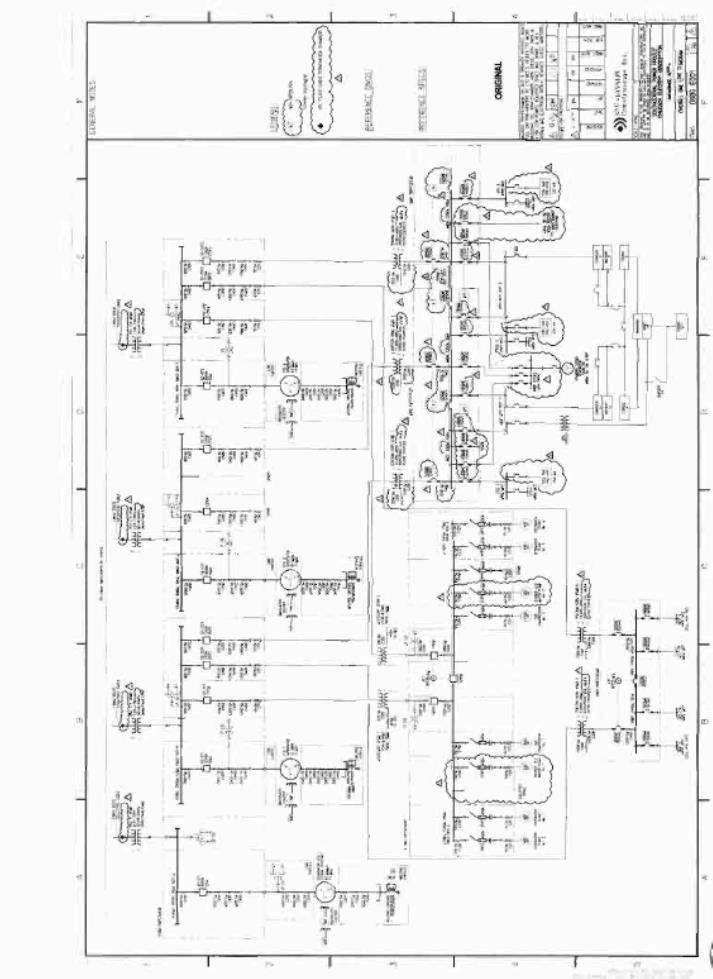
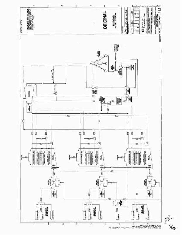
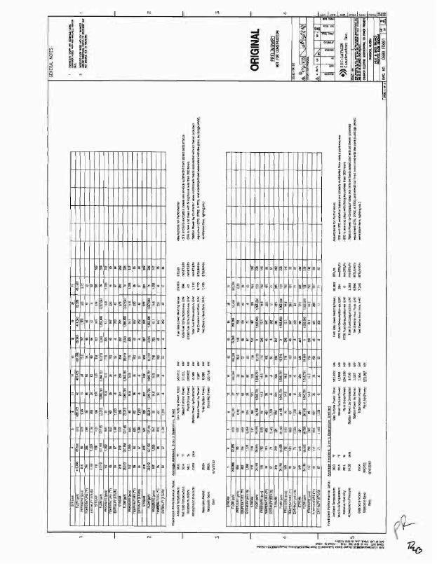
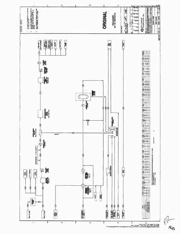
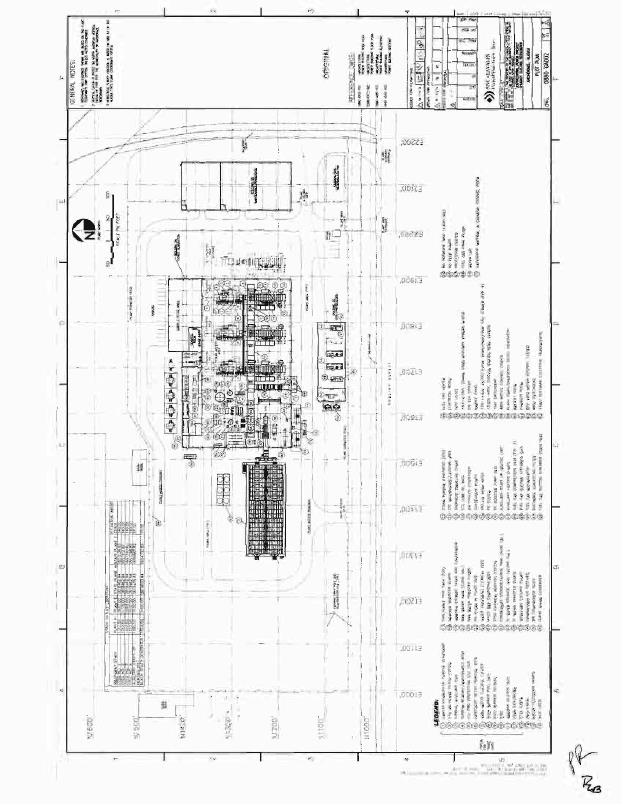
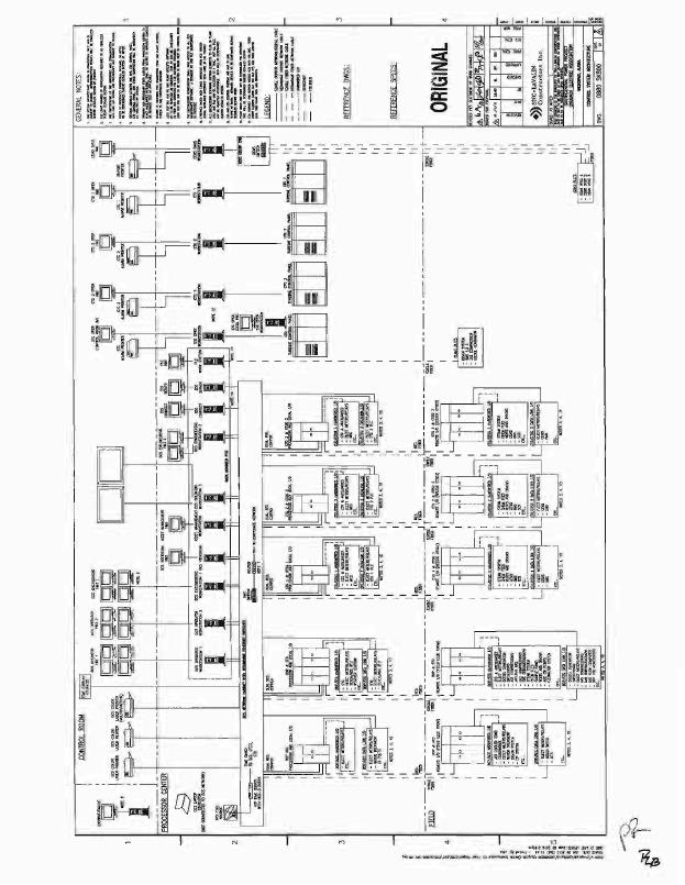
SPP Tool List
|
Item Description |
Quantity |
|
Balancing machine, IRD B50 |
1 |
|
Telehandler 8000 lbs (Cat TH407) |
1 |
|
Fork Lift 6000 lbs (Mitsubishi FG30N) |
1 |
|
LM6000 Engine stands (TCT style) |
1 |
|
Man Lift OSHA Approved (Genie 60' Articulating Boom) |
1 |
|
IR Camera FLIR |
1 |
|
18x80 machine lathe (Clausing or equal with 2 Chucks) |
1 |
|
Snap On Tool Sets (9200AGSO with 9000GS2 adder) |
3 |
|
Snap On Tool Sets (9500GSO with 9000GS5O adder) |
3 |
|
Horizontal band saw (Do All or equal) |
1 |
|
Vertical milling machine (Bridgeport Series 1 R8, Chrome, Bal screws, 3 Axis Poer feed with tooling) |
1 |
|
LM6000 Engine Cart |
1 |
|
Grit Blast Cabinet (full recovery @64 cubic feet) Flip-Top Cabinets with Side Door Opening |
1 |
|
Ultrasonic Parts cleaning station |
1 |
|
Diesel engine driven welder 400 amp (Lincoln or Miller) |
1 |
|
Battery Testing System, Albert CRT-400 |
1 |
|
Hytorc Hydraulic Wrench, 3/4 and 1" drive |
1 |
|
Optical Alignment System for Pumps and Motors, (Ludeca Optalign system) |
1 |
|
100 Ton Hydraulic press (OTC 1857) |
1 |
|
Vertical band saw (Do All or equal) |
1 |
|
Vibration Probe Calibrator. (TK3) |
1 |
|
Porta-Power Set (Enerpac) |
1 |
|
14x36 machine lathe (Hardinge/ Sharp or equal, tool room/high precession with 2 chucks) |
1 |
|
Portable Ultra Sonic Flow meter |
1 |
|
Three Phase Power Quality Analyzer |
1 |
|
Electric Conduit Bender, Greenlee |
1 |
|
Tub Style Parts Washers for Solvent-Based Cleaning Solutions |
1 |
|
Vacuum Pump, Industrial bench type |
3 |
|
4-20mA Process Loop Calibrator Fluke 744 |
1 |
|
Tig welding machine, syncro wave, Lincoln or Miller |
1 |
|
Snap On Tool Boxes (KRL 722) |
6 |
Note:
Vendor/Manufacturer requires Owner approval prior to purchase of tools or equipment


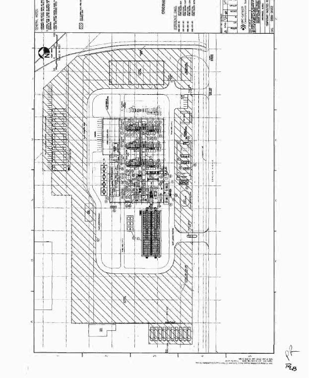
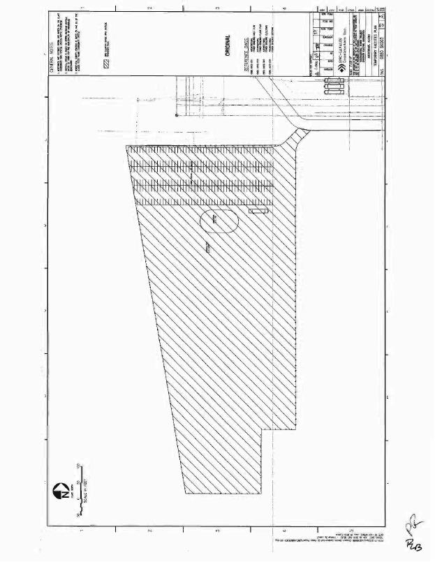
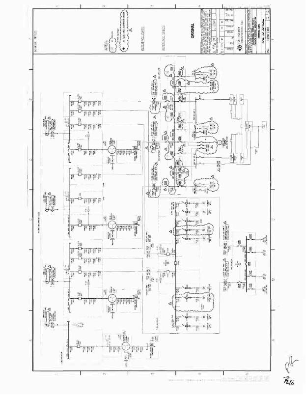
200 MW COMBINED CYCLE PROJECT
ANCHORAGE, ALASKA
SOUTHCENTRAL POWER PROJECT
Engineering, Procurement & Construction (EPC) Contract
APPENDIX J - PROJECT SCHEDULE
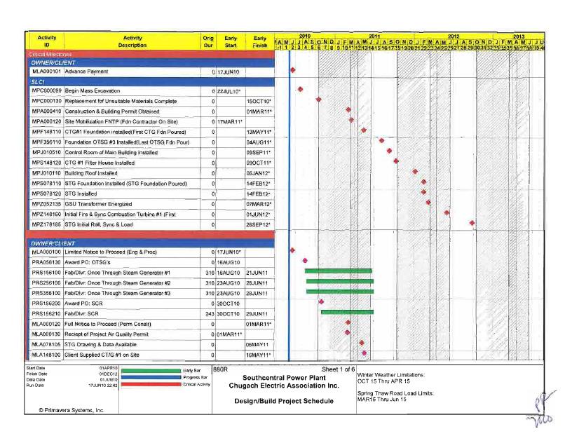
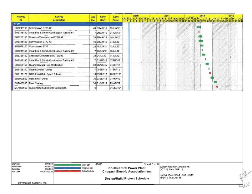
200 MW COMBINED CYCLE PROJECT
ANCHORAGE, ALASKA
SOUTHCENTRAL POWER PROJECT
Engineering, Procurement, & Construction (EPC) Contract
APPENDIX K - EXECUTION PLAN
EXECUTION VERSION
CONTRACT NUMBER 51008
TABLE OF CONTENTS
|
1. |
GENERAL |
1 | |
|
1.1 |
Inspection |
1 | |
|
2. |
SITE OVERVIEW |
1 | |
|
2.1 |
Laydown/General Use Area |
1 | |
|
2.2 |
Custody |
2 | |
|
2.3 |
Site Access and Use |
2 | |
|
2.4 |
DELETED |
3 | |
|
2.5 |
Construction Services |
3 | |
|
3. |
PROJECT MANAGEMENT |
5 | |
|
3.1 |
Mobilization |
5 | |
|
3.2 |
Project Implementation Plan (PIP) |
5 | |
|
3.3 |
Site Security Plan |
6 | |
|
3.4 |
Industrial Health and Safety Program |
7 | |
|
3.5 |
Environmental Protection Plan |
10 | |
|
3.6 |
Emergency Response Plan |
10 | |
|
3.7 |
Quality Plan |
12 | |
|
3.8 |
Document Control and Records Management |
15 | |
|
3.9 |
Communication Plan |
16 | |
|
4. |
PROCESS MANAGEMENT |
18 | |
|
4.1 |
Scheduling |
18 | |
|
4.2 |
Engineering/Design |
19 | |
|
4.3 |
Procurement |
21 | |
|
4.4 |
Startup/Commissioning |
21 | |
|
5. |
TRAINING AND PROCEDURES |
22 | |
|
5.1 |
Training |
22 | |
|
5.2 |
Procedures |
23 | |
|
6. |
OPERATIONS AND MAINTENANCE MANUALS |
23 | |
|
6.1 |
O&M Manual |
23 | |
EXECUTION VERSION
CONTRACT NUMBER 51008
This Execution Plan is part of that certain Engineering, Procurement and Construction Contract, made and entered into as of June 18, 2010 (as further amended, restated, supplemented or otherwise modified from time to time, the "Contract"), by and between Chugach Electric Association, Inc., an Alaska electric cooperative ("Company"), and SNC-Lavalin Constructors, Inc., a corporation formed under the laws of the State of Delaware ("Contractor"). Capitalized terms used herein but not otherwise defined herein shall have the respective meanings set forth in the Contract.
1.GENERAL
1.1 INSPECTION
|
a) |
Contractor shall be responsible for coordinating and executing required inspections. |
|
b) |
Contractor shall notify inspection entities in adequate time to schedule their inspection without holding up the Work. If there is no published notification time, provide notice at least two workdays in advance of scheduled inspection stimuli. |
|
c) |
Contractor shall provide means of safe access for inspectors of the Work. |
|
d) |
For systems requiring testing or calibration, Contractor shall provide the necessary equipment and materials to prove operation to the inspector. |
|
e) |
Contractor's Designer of Record shall prepare a special inspection program ("Special Inspection Program") in accordance with IBC Chapter 17. The Special Inspection Program shall be included with the plan review submittal to the Municipality of Anchorage. - |
|
f) |
Contractor's Designer of Record shall prepare a seismic and wind quality assurance program(s), if applicable, in accordance with IBC Chapter 17. The quality assurance program(s) shall be included with the plan review submittal to the Municipality of Anchorage. |
|
g) |
Observations and reports required by the seismic quality assurance program shall be included by Contractor in the Project. |
|
h) |
Reports of all inspections and tests shall be provided to Company. |
2.SITE OVERVIEW
2.1LAYDOWN/GENERAL USE AREA
|
a) |
Company will provide Contractor with access, temporary rights of way or easements and any road improvements to Dowling Road or Electron Drive to occupy adjacent property located to the southwest of the Site (1480 W Dowling Rd.; part of the W1/2 NE 114 NW 1/4, Block 3, Denali Industrial Park Subdivision). This property is a 15.88 acre site upon which a new 11.50 acre gravellaydown area is to be developed by Contractor in accordance with Municipality of Anchorage requirements. |
1
EXECUTION VERSION
CONTRACT NUMBER 51008
|
b) |
Contractor shall develop and implement a Contractor-specific usage plan for the Project laydown area for postulated use during Work executed by for the Project laydown area for postulated use during Work executed by Contractor under the Contract. Snow accumulation allowance to be determined. |
2.2CUSTODY
|
a) |
Contractor shall implement a Company-approved process for acceptance of care, custody, and control of the designated Project laydown/general use area for Contractor's use during Project development. The process shall include: |
|
1) |
Joint inspection/walkdown of the designated areas prior to the start of any physical modification or mobilized presence . |
|
2) |
Written notification of any general property conditions which would affect the cost or proper completion of the Work. |
|
b) |
Contractor shall field verify all dimensions, establish all construction lines and levels, specified locations, elevations and positions of all parts of the Work prior to beginning any fabrication, installation or construction work. Contractor shall check anchor bolt locations for accuracy, check foundations for proper elevations and embedments, and check support steel for square and level, before erection. Contractor shall use property benchmarks to establish elevations and locations. Contractor shall bring all errors, omissions, or discrepancies to the attention of Company's Representative and not proceed with the Work until all discrepancies have been resolved. If, after Work has begun, conditions are uncovered that are not as anticipated, Contractor shall immediately notify Company's Representative of such conditions . |
|
c) |
Where the proper fabrication or erection of any part of the Work depends on the work of other Persons, Contractor shall verify all necessary dimensions by field measurement. |
2.3 SITE ACCESS AND USE
|
a) |
Contractor shall provide storage, working areas, access ways, and Site security required to perform the Work in a safe and secure manner consistent with the requirements of Company. Such facilities shall, with the agreement of Company, be removed from Site on completion of the Work and any laydown areas shall be restored to prior conditions. |
|
b) |
Equipment and Materials storage shall meet or exceed all OEM requirements and prudent industry practice. |
2
EXECUTION VERSION
CONTRACT NUMBER 51008
2.4 DELETED
2.5 CONSTRUCTION SERVICES
Contractor shall be responsible for providing and installing all temporary construction-related infrastructure services and facilities during Plant construction and commissioning periods.
|
a) |
Temporary Electricity Supply |
Contractor shall identify and quantify construction and startup electrical power including the load profile for the duration of the Work. Company shall provide temporary electric power service to the load side of service meter(s). Company will provide one or more 480V, 30 metered power drops to Contractor-identified locations (near service line poles). Metering stations shall be provided by Contractor and the meter(s) shall be supplied by Company. Contractor shall include all Equipment for and installation of the temporary power services. The costs of construction power shall be paid directly by Company. When construction power is no longer required, Contractor shall notify Company, and disconnect and remove all temporary Equipment to the satisfaction of Company. On-Site underground construction power infrastructure may be abandoned in-place subject to compliance with Applicable Law.
|
b) |
Temporary Potable Water Supply |
Company shall arrange for and provide all construction and commissioning water throughout the performance of the Work. Company shall be responsible for an AWWU-approved service connection at the Site battery limits (NE corner, see Site plan and/or the south service extension to be designed/installed by Company). Contractor shall be responsible for all temporary and permanent Site water systems.
|
c) |
Sanitation |
Company shall provide a temporary 2-inch pressure connection for acceptance of sewage at the NE battery limit (HDPE-17 approximately six feet below grade, see attached sketch). Contractor shall be responsible for all sewer connections and collection per AWWU requirements. The temporary connection shall be available only until such time as Contractor can make connection to the permanent effluent to the south sewer extension (to be provided by Contractor as part of the Work). Temporary lift stations are permissible provided that they are removed and Site restoration is complete prior to Substantial Completion.
|
d) |
Contractor shall provide temporary office facilities for Company Site staffing with OSHA access on-Site within reasonable walking distance of the main construction areas. All office areas shall be secure and lockable. |
|
1) |
One (1) furnished executive office with conference area for 4-5 people |
3
EXECUTION VERSION
CONTRACT NUMBER 51008
|
2) |
Five (5) furnished offices |
|
3) |
Pool/cubicle area for up to ten (10) people |
|
4) |
General access to a conference room for 12-15 people |
|
5) |
Reception area furnished for a receptionist/administrative assistant |
|
6) |
Communication room |
|
7) |
Lockable storage |
|
8) |
Hospitality area |
|
9) |
Toilet(s) |
|
10) |
Arctic entries/mudrooms |
|
11) |
All identified work locations to be pre-wired for power and voice/data communication (Cat-6) |
|
e) |
Contractor shall provide the following administrative services through Substantial Completion: |
|
1) |
High-speed internet access (wireless and LAN) |
|
2) |
Janitorial |
|
3) |
Large-format printing/plotting |
|
4) |
Telecommunication connection (national and international) |
|
f) |
Other Site Services |
Contractor shall provide and maintain at a minimum the following services at its cost until Substantial Completion: jobsite ingress/egress routes (vehicular and pedestrian), communication (telephone, radio, high-speed internet); sanitary facilities; waste disposal (liquid and solid effluents including hazardous waste), dust control, snow/ice removal, construction related parking, construction heating, construction lighting.
|
g) |
Restoration of Temporary and Construction Services |
Contractor shall remove temporary utilities, Contractor Equipment, Non-Company Materials and facilities. Contractor shall clean and repair damage to Company's facilities caused during performance of the Work. Temporary modifications shall be completely restored to the condition at the time of transfer of care, custody, and control to Contractor unless specifically modified in writing by Company.
4
EXECUTION VERSION
CONTRACT NUMBER 51008
3.PROJECT MANAGEMENT
3.1MOBILIZATION
|
a) |
Contractor shall implement fully-matured, Company-approved Site management programs that shall include the following as a minimum. |
|
1) |
Project Implementation Plan (PIP) |
|
2) |
Site Security |
|
3) |
Safety and Industrial Health |
|
4) |
Environmental Protection |
|
5) |
Emergency Response |
|
6) |
QA/QC |
|
7) |
Document Control and Records Management |
|
8) |
Communication |
|
b) |
Contractor shall submit all plans to Company for review and approval no later than three months following the first to occur of Limited Notice to Proceed or Full Notice to Proceed. |
3.2PROJECT IMPLEMENTATION PLAN (PIP)
|
a) |
Contractor shall prepare and submit to Company a Project Implementation Plan (PIP). The PIP shall include the following as a minimum. |
|
1) |
Project schedule |
|
2) |
Startup and Commissioning schedule |
|
3) |
Labor/Craft staffing |
|
4) |
Soil and backfill management |
|
5) |
Traffic management |
|
6) |
Storm water pollution prevention |
|
7) |
Dust suppression • |
|
8) |
Snow removal |
|
9) |
Plan drawing of Iaydown, parking, trash storage and recycling areas |
5
EXECUTION VERSION
CONTRACT NUMBER 51008
|
10) |
Construction heavy lift |
|
11) |
Welding qualifications and welding procedures |
|
12) |
Welder certifications |
3.3SITE SECURITY PLAN
|
a) |
Contractor shall implement general 24 hour Company-approved general security programs and procedures for the Site. Site security shall be provided by personnel specifically trained and qualified with the knowledge and skills to protect Company assets and personnel. Security personnel shall be provided by a qualified security entity licensed to provide the service in Alaska. |
|
b) |
Contractor shall provide Site security programs commensurate with and responsive to Applicable Law and Prudent Industry Practices. The plan shall encompass all areas of security including controlling Plant access, computer security, and routine patrols using qualified security personnel capable of recognizing and responding to potential or identifiable threats. Periodic in-depth audits shall be conducted to ensure that Site security measures are adequate. Company shall be provided with written audit reports immediately following audit completion and the development of any required program remediation. |
|
c) |
Contractor shall establish and implement programs to control access to all Contractor-controlled areas by any Person including Subcontractors, visitors, Company's contractors, and Company's and Contractor's employees. This program shall be such that all personnel entering or leaving the Plant are monitored (including verification of mandated personal protective equipment). In addition, a method of tracking all personnel on Site at all times shall be established and implemented to assist in ensuring all Site personnel are accounted for in the event of an emergency. |
|
d) |
Contractor shall establish and implement programs outlining the requirements for security patrols and rounds commensurate with each potential threat level for the Site. These programs shall be designed to suit the needs of the Plant based on an evaluation of the local area and Applicable Law. |
|
e) |
Audits of the Plant security programs shall be conducted at a minimum annually. The audit shall assess the performance of the security program for the potential and existing threats to the Plant. The goal of the security audit is to eliminate any security deficiencies before they result in a security incident. Company shall be furnished reports resulting from such audits and from the completion of any requirements and recommendations resulting from such audits. |
|
f) |
Site security shall include: |
6
EXECUTION VERSION
CONTRACT NUMBER 51008
|
1) |
Trained security staff to preclude casual and malicious battery limit penetration into Contractor-controlled areas. |
|
2) |
Processes shall be implemented to prevent theft of Project and personal material from controlled areas. |
|
3) |
Security reporting requirements and authorities shall be clearly defined. |
|
4) |
Communication links shall be established between Site security staff and local law enforcement and other emergency response agencies that deal with security issues within the Anchorage jurisdiction. |
|
g) |
Contractor shall provide temporary security fencing around the Site until the permanent Site security system is in place. Any temporary security fencing shall have suitable movable gates or fence sections to allow emergency access for fire-fighting vehicles and equipment in accordance with Municipality of Anchorage requirements. |
3.4INDUSTRIAL HEALTH AND SAFETY PROGRAM
|
a) |
Contractor (following Company review and acceptance) shall implement a well-documented, Site~specific industrial health and safety program that clearly communicates Contractor commitment to Site safety and Applicable Law and Site-specific conditions through all phases of the Work. The approved Contractor program shall be applicable to all personnel at the Site, performing the Work or otherwise within the control of Contractor or any of its Subcontractors. Contractor's program shall meet the following objectives and commitments: |
|
1) |
The safety, health, and quality of life of Site workers and visitors shall be ensured through safety engineering, use of personal protective equipment, observation of safe work practices/procedures, and effective management. |
|
2) |
New safety hazards and health risks at every activity level at the Site during performance of the Work shall be identified and addressed to preclude injury and fatality. |
NOTE:
Hazards and risks shall be communicated immediately to any worker who may be in imminent danger from the hazard or risk and to supervision/management charged with eliminating or controlling the hazard or risk. Persons responsible for new hazards or risks shall immediately address their elimination or control.
|
b) |
Contractor shall incorporate into this plan comprehensive method statements for all major Work. The method statements shall address working methods, Plant utilization, construction sequence, and safety arrangements. The requirements of applicable national and local Site
7 |
EXECUTION VERSION
CONTRACT NUMBER 51008
safety policies, Applicable Law, Prudent Industry Practices, and all requirements outlined in the Specifications and the Contract shall be incorporated into the program. |
|
c) |
Contractor program shall include the following minimum approved safety protocols: |
|
1) |
HazCom (with chemical exposure limits per the latest revision of the NIOSH Pocket Guide to Chemical Hazards) |
|
2) |
HazMat |
|
3) |
Confined Space Entry |
|
4) |
Lock-outlTag-out (LOTO) |
|
5) |
Electrical Safety (including Hot Work and arc-flash considerations) |
|
6) |
Hot Work/Cold Work (open flame, welding, cryogenic, etc.) |
|
7) |
Fire/Explosion Prevention (including smoking) |
|
8) |
Assured Grounding |
|
9) |
Compressed Gas Handling and Storage |
|
10) |
Rigging and Lifting J |
|
11) |
Elevated Work (Fall Prevention/Protection, Ladders/Stairs, Scaffolds, Walkways, Platforms) |
|
12) |
Below-grade Work (Trenching, Excavating) |
|
13) |
Safety Barricading |
|
14) |
Hearing Protection and Conservation |
|
15) |
Respiratory Protection |
|
16) |
Blood borne Pathogens |
|
17) |
Personal Protection Equipment (PPE) |
|
18) |
Rotating Machinery |
|
19) |
Powered Industrial Machinery |
|
20) |
Incident and Near-miss Investigation and Reporting |
|
21) |
First Aid Equipment and Materials |
|
22) |
Site Housekeeping |
8
EXECUTION VERSION
CONTRACT NUMBER 51008
|
23) |
Pre-work safety reviews (tailgate meetings) |
|
24) |
Routine Project Safety Meetings |
|
25) |
Stop-work and Safety Stand-downs |
|
d) |
Contractor shall provide a minimum of one on-Site first responder (EMT-Level 1) during all hours of scheduled craft activity and a fully-equipped and staffed first aid/injury stabilization station at Full Notice to Proceed. Contractor shall assign a full-time project safety manager ("Project Safety Manager") at Site subsequent to full mobilization until Substantial Completion. For Site work contemplated in 2010, Contractor will utilize Subcontractor safety personnel. Project staffing with field safety representatives shall be commensurate with the level of field activity and the ability for relatively continuous monitoring of the Work. The Project Safety Manager shall have overall authority for coordination and implementation of all Site industrial health and safety practices, policies, and programs. |
|
e) |
Contractor shall maintain an up-to-date file of Material Safety Data Sheets (MSDS) and Physical Agent Data Sheets (PADS) for all hazardous materials and physical agents on-Site and under the control of Contractor in accordance with Applicable Law. The MSDSs and PADSs must be available to Company and Contractor and their respective Project staff anytime prior to material use. |
|
f) |
Contractor shall provide baseline and refresher safety training and qualification at discrete levels for first responders, long-term workers (>2 wk), short-term unescorted workers, and escorted visitors. Such training shall include written instructions incorporating the relevant portions of Contractor's program. Contractor shall ensure that all workers are properly informed, consulted, and trained on health and safety issues in accordance with the approved Site program as well as Applicable Law. Worker training shall include the locations of the nearest care facilities. |
|
g) |
Contractor shall provide all safety equipment for use on the Project. Where such equipment is subject to statutory inspections, Company shall have access to copies of the inspection reports. Contractor shall provide all required PPE and reasonable replacement quantities (excluding safety shoes). |
|
h) |
The Project Safety Manager shall maintain baseline and refresher safety training and qualification records matrix. In addition, the Project Safety Manager shall monitor training programs and maintain quality records for all safety-related specialty qualifications (e.g., Crane Operator, Forklift Operator, SCBA, Fire Watch, Scaffold Inspector, Radiographer). |
|
i) |
The Project Safety Manager shall ensure that all regulatory inspections and reporting are completed as required. |
9
EXECUTION VERSION
CONTRACT NUMBER 51008
3.5ENVIRONMENTAL PROTECTION PLAN
|
a) |
Contractor shall implement a Company-approved environmental protection plan (the "Environmental Protection Plan") for the Site and in connection with the Work that adhere to the following guidelines: |
|
1) |
Implement all practices necessary to protect the health, quality of life, and environment of the communities surrounding the Site. |
|
2) |
Identify and comply with all Applicable Laws and governing the stewardship and protection of environmental resources from hazards associated with the Work. |
|
3) |
Train workers and publish information concerning the environmental risks and risk mitigation associated with assigned job responsibilities. |
|
4) |
Reconcile the Site Environmental Protection Plan with emergency response planning for any Site environmental incidents. |
|
b) |
Contractor's Environmental Protection Plan shall address the following: |
|
1) |
Solid waste |
|
2) |
Hazardous waste |
|
3) |
Sanitary waste |
|
4) |
Fuel storage areas |
|
5) |
Equipment maintenance |
|
6) |
Spill response (including notification procedures, response supplies, responding contractors, training requirements, and disposal methods) |
|
7) |
Noise ordinance compliance |
|
8) |
Title I air quality construction permit compliance |
|
9) |
Storm water controls and the Project SWPPP |
|
10) |
On-Site contaminated soil |
|
11) |
List of all Subcontractors used to maintain environmental compliance |
3.6EMERGENCY RESPONSE PLAN
|
a) |
Contractor shall develop an emergency response plan ("Emergency Response Plan") that prioritizes the preservation of public/worker health
10 |
EXECUTION VERSION
CONTRACT NUMBER 51008
and safety, the protection of the environment, and protects/preserves the extensive investment represented by the Work. |
|
b) |
Contractor shall implement an Emergency Response Plan that identifies, prevents, mitigates, and recovers from postulated emergency and abnormal event scenarios during and connected with the Work. Potential risks to be addressed in emergency planning include: |
|
1) |
Acts of God (natural catastrophes) |
|
2) |
Fires/explosions |
|
3) |
Security breaches |
|
4) |
Civil disturbances |
|
5) |
Environmental releases of regulated substances |
|
6) |
Personnel accidents and injuries |
|
7) |
Public health threats |
|
8) |
Emergency shutdowns |
|
9) |
Service interruptions. |
|
c) |
Emergency response shall include evacuation planning when required for control and mitigation of abnormal events. Emergency planning shall consist of the following actions. |
|
1) |
Identify and assess the risks associated with the Site and the Work. |
|
2) |
Define and implement measures and practices to prevent these risks from becoming emergencies. |
|
3) |
Define and implement an appropriate course or plan of action to take in the event that these risks become actual emergencies. This shall include the establishment of response organization/matrix capable of managing and coordinating the response and accessible staging of adequate material and equipment resources. The response organization shall include a team of trained and qualified staff, off-Site responders (e.g., police, firefighters, medical responders, spill response contractors and cooperatives, corporate support resources). This organization shall be linked via emergency notification protocols that include applicable Governmental Authorities. |
|
d) |
The Emergency Response Plan shall include the following as a minimum for each event scenario: |
11
EXECUTION VERSION
CONTRACT NUMBER 51008
|
1) |
Immediate Response - Actions that if not performed would lead to further deterioration in the margin of safety for personnel, the environment, and high value equipment. These actions are intended to stabilize the hazardous environment to which personnel and equipment are exposed and/or to separate or shield personnel and equipment from the source of the hazard. |
|
2) |
Mitigation - Processes that are to be implemented to ameliorate existing hazardous conditions and prevent further injury or loss. |
|
3) |
Restoration - Actions required that will return the Site to pre-emergency conditions. |
|
e) |
Emergency planning shall identify and comply with all Applicable Law. |
|
f) |
All Site workers shall receive indoctrination training prior to unaccompanied Site access. Individuals filling designated emergency response roles shall be drilled on a periodic basis (no less than annually) in Site emergency response. |
|
g) |
Contractor shall provide unimpeded Site access for emergency vehicles and responders; and shall provide and maintain access to all fire hydrants once the Plant fire loop is operational. |
3.7QUALITY PLAN
|
a) |
Contractor shall implement a Company-approved Project quality plan (the "Project Quality Plan") through selective use of experienced specialists and effective project management. All quality-related activities shall be accomplished by competent staff that have been trained and qualified through a defensible, systematic process. |
|
b) |
Contractor shall designate a project quality manager ("Project Quality Manager") to define and maintain project quality standards and ensure effective and complete implementation of the Project Quality Plan. The Project Quality Manager shall report directly and have unimpeded access to Contractor upper corporate management for all quality-related issues. The Project Quality program shall function under the direction and guidance of the Project Quality Manager. The Project Quality Manager shall maintain surveillance over all quality-related activities through direct supervision of Project Quality personnel in all areas subject to surveillance. |
|
c) |
The authority of the Project Quality Manager in matters related to the Project Quality Program shall be absolute and cannot be overruled by Contractor on-Site Project management. The Project Quality Manager shall have the authority to suspend any operation or to rejectmaterials, services, or procedures that do not comply with approved standards. Quality operations shall not be influenced or compromised by considerations such as schedules, rework, costs/budgetary
12 |
EXECUTION VERSION
CONTRACT NUMBER 51008
responsibilities, or engineering changes since all deviations from requirements shall be coordinated with the Project Quality Manager. |
|
d) |
Stringent controls shall be implemented to ensure that adequate records for all quality-related activities are documented and maintained to serve as defensible evidence of quality. All final reports shall be reviewed by Contractor and Company. |
|
e) |
The Project Quality Plan shall include: |
|
1) |
Design Control (CCC) - A design control process shall ensure (through review and testing) that Plant, system, component, and process design and modification input is correctly translated into specifications, drawings, and instructions. All design bases shall be documented including design changes and field modifications. |
|
2) |
Identification and Control of Materials, Parts, and Components – A process shall confirm that Materials, parts, and components (including subassemblies) are identified and controlled to ensure that only correct and accepted items are used and installed during any quality-related activity. |
|
3) |
Instructions, Procedures, and Drawings - All quality-related activities shall be implemented using pre-approved instructions, procedures, and drawings including qualitative and quantitative performance criteria. |
|
4) |
Document Control- A systematic control process for document use and revision shall be implemented for documents that specify quality requirements or direct quality-related activities. |
|
5) |
Quality Records - A process shall be implemented for identifying quality records and establishing requirements for retention, acceptance, marking, indexing, storage, preservation, safekeeping, and retrieval. |
|
6) |
Procurement - A program shall control authorization and purchase of quality-related items, Materials, parts, Equipment, and services; instrumentation; calibration; and other quality-related purchases. |
|
7) |
Handling, Storage, and Shipment - Approved instructions shall establish methods for cleaning, packaging, and preserving Material/Equipment to preclude damage, deterioration, and loss. |
|
8) |
Vendor Qualification and Product Quality Control - A documented program shall ensure that purchased items and services conform to procurement specifications including source evaluation and selection (to the extent such supplier is not on Company-approved supplier listthe Approved/Preferred Subcontractor List), objective evidence of quality, source surveillance, and receipt examination. |
13
EXECUTION VERSION
CONTRACT NUMBER 51008
|
9) |
Nonconforming Material, Parts, and Components - A process shall control (identify, notify, document, segregate, recall, and dispose) items, services, and activities which are non-compliant with specifications or the Contract. |
|
10) |
Control of Special Processes - A written process shall control abnormal and complex activities that affect quality (e.g., heat/chemical treatment, NOT, joining, performance testing). The special process and implementing equipment/personnel shall undergo verifiable qualification per applicable codes and standards. |
|
11) |
Test Control - A program for controlling all test activities that affect quality shall be implemented to verify that tests are performed using written procedures containing complete and appropriate standards of acceptance. |
|
12) |
Control of Measuring and Test Equipment - A program shall ensure that inspection, testing, and measuring devices used for activities or items affecting quality are controlled/maintained and calibrated at prescribed intervals or prior to use with certified primary/secondary standards or approved calibration bases. |
|
13) |
Status of Inspection, Test, and Operation - A program shall ensure that inspection and testing commitments are satisfied at the required frequency through application of approved testing and inspection protocols. All test and inspection deficiencies shall be exposed to root cause analysis and corrective action. |
|
14) |
Process Inspection - A quality control evaluation process shall verify conformance to approved standard characteristics of those items and activities that affect quality. |
|
15) |
Audits - Methodologies shall be implemented to expose quality-related activities and processes to periodic internal evaluations. |
|
16) |
Corrective Actions - A timely corrective action implementation and tracking process shall ensure that conditions adverse to quality (e.g., failures, malfunctions, deficiencies, deviations, audit findings, defects, nonconforming items) are promptly identified and corrected in accordance with the Contract. |
|
17) |
Quality Records - Approved and implemented programs and procedures that identify and result in quality-related records (e.g., forms, data sheets, worksheets, certificates, reports) shall specify the minimum required content, distribution and record retention period for all generated records and shall be in accordance with the Contract. Quality records shall be legible, identifiable, and retrievable. Record management systems shall define minimum acceptable characteristics for quality record submittals. Quality records shall be protected against damage, deterioration, or loss. |
14
EXECUTION VERSION
CONTRACT NUMBER 51008
3.8DOCUMENT CONTROL AND RECORDS MANAGEMENT
|
a) |
Contractor shall implement an ISO-9000-level program to manage Project documentation and records associated with identified quality-related Work activities. The program shall include management and control functions from record/document creation until such records/documents are turned over to Company. The program shall manage and control documents that specify quality requirements, prescribe activities that affect quality, or record quality-related observations or measurements (e.g., instructions, procedures, drawings, specifications, calculations, data sheets, reports, certifications). The program shall include two elements: |
|
1) |
Document Control - Systematic control of quality-related document development (initial and revision), approval, distribution, and use. |
|
2) |
Quality Records - Identification and definition of the acceptability of quality records and establishment of requirements for retention, acceptance, marking, indexing, storage, preservation, safekeeping, retrieval, and obsolete/superseded document handling. |
|
b) |
Contractor shall provide a consistent Project-based hierarchical document and equipment numbering system, including all scope provided by Subcontractors. In the event that Subcontractor information is not provided to Contractor in this manner, Contractor shall superimpose the Project reference. |
|
c) |
Contractor shall provide Company with a full list of all Project documentation (MS Excel) with data fields as agreed between Company and Contractor. |
|
d) |
All pages of Project quality-related documents shall display the Project identification, document record identifier, title, revision number, revision date, and page numbering. Document records identifiers shall be unique (without option of reuse) to an approved document. Document revisions shall clearly identify revised text and graphics. Approval shall be clearly identified by the approving authority name, title, signature, and approval date. |
|
e) |
Historical records of the development and revision process including concept, draft, review and comment, and approval shall be maintained. All quality-related programs and procedures shall be reviewed for technical and application accuracy prior to approval and implementation. |
|
f) |
An approved method shall be implemented to ensure that only latest approved revisions of documents are applied to quality-related tasks. The same methodology shall preclude compromising the integrity of the document control process through controlled access and distribution. An approved method shall be implemented that verifies complete replacement and destruction of superseded documents and the removal/destruction of time-sensitive documents following expiration of
15 |
EXECUTION VERSION
CONTRACT NUMBER 51008
the approved use period. Revisions shall be documented, reviewed, and approved by the same organizations that performed the original review and approval unless other organizations are specifically designated. |
|
g) |
Users of quality-related documents shall be instructed on proper use of documents for quality-related activities and prohibitions on misuse of controlled documents. A method shall be established to address the proper applications and prohibitions for field changes to procedures. The scope of non-substantive revisions shall be clearly defined. |
|
h) |
Contractor shall establish a system of interim care, custody, and control of Project quality records for turnover to Company. This system shall include: . |
|
1) |
Custodial Responsibility |
|
2) |
Receipt Control |
|
3) |
Processing Status |
|
4) |
Storage, Preservation, and Safekeeping |
|
5) |
Retrieval |
|
6) |
Disposition |
|
7) |
Obsolete Document Retrieval and Disposition |
|
8) |
Document Control and Records Management |
3.9COMMUNICATION PLAN
|
a) |
Public Relations |
Contractor shall limit media/public interface to a single authorized spokesperson in consultation with Company's public relations department during normal Plant conditions as well as during abnormal events. Other Contractor representatives may be designated to provide safety, technical, environmental, or other relevant support to the designated spokesperson. All other workers shall refer public inquiries to the authorized spokesperson.
|
b) |
Meetings |
|
1) |
During all active phases of the Project Contractor shall participate in monthly Project review meetings ("Project Review Meetings") with Company management. Each Contractor discipline leads shall update Company on the discipline progress to date, review the Project overall schedule, review activities currently in progress, and discuss problem areas and the plan developed by
16 |
EXECUTION VERSION
CONTRACT NUMBER 51008
Contractor to address and resolve such problems. Contractor shall be responsible for taking minutes of the meetings and the subsequent publication to Company. |
|
2) |
Contractor shall host weekly progress meetings at the jobite for safety; construction and startup/commissioning; quality issues and action items; and progress versus schedule. Contractor shall record and publish meeting minutes, copies of which shall be furnished to Company for review and comment. |
|
c) |
Technical Reporting - During periods of construction execution and startup, Contractor shall provide, at a minimum, weekly written reports. During periods of intense activity or schedule slippage, Contractor shall increase the reporting frequency to daily or as otherwise agreed between Company and Contractor. The report shall status the following (as applicable) in summary format: |
|
1) |
Safety |
|
2) |
Schedule - Critical Path and 3-week look-ahead |
|
3) |
Engineering Issues |
|
4) |
Procurement Issues |
|
5) |
Construction |
|
- |
Foundations/Concrete |
|
- |
Building/Steel Erection |
|
- |
Equipment Erectionllnstallation |
|
- |
Piping |
|
- |
Cable tray/Conduit Installation |
|
- |
Wire/Cable Pulling (including P2P) |
|
- |
Construction Testing |
|
6) |
Commissioning/Startup |
|
- |
System/subsystem turnover (Punchlist) |
|
- |
System testing |
|
- |
Integrated testing |
|
- |
Punch list for Final Completion |
|
d) |
Written Communication |
17
EXECUTION VERSION
CONTRACT NUMBER 51008
|
1) |
File Sharing and Document Transmittal - Project electronic file sharing and transmittal shall be through ProjectSolve (protocol to be developed). |
|
2) |
Contractor notifications shall be submitted in both electronic and hardcopy format with appropriate original signatures. |
|
3) |
Final Submittal Format - All documents submitted to Company by Contractor shall be in the form of four (4) hard copies, on two (2) sets of DVDs containing the CAD drawings, database files, or word processor files as appropriate, except as specifically noted elsewhere in this document, and shall be drawn at a proper scale and be of sufficient quality to ensure legibility. Electronic files submitted shall be in the following format: |
|
- |
CAD files - AutoCAD compatible with latest software version |
|
- |
Word processor files - Microsoft Word |
|
- |
Spreadsheets - Microsoft Excel |
|
- |
Database files - Microsoft Access |
|
- |
Schedules - Primavera (*.xer file protocol) |
|
- |
Adobe Acrobat (*.pdf) for formats not listed above |
|
4) |
All drawings provided, included vendor drawings, and shall be dimensioned in English units. |
|
5) |
Cable and conduit lists, line lists, valve lists, and instrument index are to be provided in Excel or database files. Electronic files shall be submitted in both native format or pdf. |
4. PROCESS MANAGEMENT
4.1 SCHEDULING
|
a) |
Contractor shall utilize Primavera P6 Enterprise Project Portfolio Management to track and record all aspects of Project schedule management. |
|
b) |
Contractor shall utilize or incorporate Contractor WBS elements in Contractor's schedule for the Project and other Company planning, schedule development, monitoring, and reporting requirements. Company and Contractor shall cooperate to ensure the schedule activity breakdown (or approved adjustments to that originally accepted) used for the Project are consistent with Contractor Project-specific WBS. |
|
c) |
Schedule Control Plan |
Contractor shall implement a Company-accepted schedule control plan ('Schedule Control Plan") that describes Project systems and procedures for planning, sequencing, scheduling, resource loading, controlling, and
18
EXECUTION VERSION
CONTRACT NUMBER 51008
reporting on the Project Schedule. The Schedule Control Plan shall include:
|
1) |
Organization (on-site and offsite with Project staff relationships)This shall include a full-time on-site Project Controller during the Work. |
|
2) |
Schedule Hierarchy |
|
3) |
Schedule development including Project Milestones. |
|
4) |
Schedule maintenance including data collection, verification, and processing |
|
5) |
Schedule analysis for performance and risk |
|
6) |
Schedule forecasting |
|
7) |
As-built schedule development, maintenance, and verification |
4.2 ENGINEERING/DESIGN
|
a) |
Formal Engineering/Design Reviews and Reports |
Contractor shall apply formal, rigorous reviews of the Project as set forth below.
Constructability Review, Operability/Maintainability Review
|
1) |
, HazOp Analysis (interim review at 60%, and final on or before 90% of complete Engineering) |
|
2) |
Arc-flash Assessment (deliverable on or before 90% complete Engineering) |
|
3) |
Failure Mode and Effect Analysis (FMEA) on critical systems. |
|
4) |
Contractor Recommended Spares list for 5 years or as available from the Subcontractor deliverable on or before September 30, 2011. |
|
5) |
Lubrication Schedule |
|
6) |
CMMS baseline data for all Plant equipment provided in Excel format (configured for import into Cascade in Company provided format; importation is the responsibility of the Company) provided before Final Completion. |
|
7) |
Control Logic Cause-Effect Matrix for each DCS logic system, provided with final drawings prior to Final Completion. |
|
8) |
Preventive Maintenance Schedule for Equipment in Excel format. |
19
EXECUTION VERSION
CONTRACT NUMBER 51008
|
9) |
Itemized Equipment List with estimated cost for each item. |
|
b) |
Design Review |
|
1) |
Contractor shall provide all engineering documents normally required for a project of this type. |
|
2) |
The Project shall utilize a secure internet based collaboration tool, for documents transmittals and control hosted by Company. |
|
3) |
Critical documents which define the overall design of the facilities are required to be submitted to Company for review and comment. As a minimum, the following documents are to be submitted for design review, comment, and approval: |
|
- |
Plant general arrangement drawings |
|
- |
Electrical one-line diagrams (including relaying) |
|
- |
Piping and instrumentation diagrams |
|
- |
Water maximum balances |
|
- |
Building arrangement and layout plans |
|
- |
Purchase specifications for all engineered equipment and components greater than $1,000,000 value |
|
- |
Relay protection drawings, calculations, and settings |
|
- |
Electrical relay settings (and associated calculations with all associated time-current curves, R-X diagrams, etc.) |
|
- |
Plant Distributed Control System (DCS) configuration block diagrams |
|
- |
DCS operation and control philosophy |
|
- |
Electrical grounding and lightning protection plans |
|
- |
Detailed startup test procedures |
|
4) |
The following are examples of documents submitted for information. |
|
- |
Storm water system sizing calculations |
|
- |
138kV duct bank thermal design ampacity calculations |
|
- |
Electrical control wiring diagrams (elementary and point-to-point) |
|
- |
Electrical interconnect drawings |
|
- |
Instrumentation loop drawings |
|
- |
Electrical short circuit and load flow versus voltage drop calculations |
|
- |
Electrical area classification plans and elevations |
|
- |
Electrical lighting calculations and layout plans |
20
EXECUTION VERSION
CONTRACT NUMBER 51008
|
- |
Soil thermal resistance test report |
|
- |
Underground conduit plan and profile drawings |
|
- |
Structure and foundation design calculations |
|
- |
Underground piping drawings |
|
- |
Equipment foundation drawings |
|
- |
Area paving and drainage drawings |
|
- |
Structural steel plan, section, and detail drawings |
|
- |
Piping composite layout drawings, including underground piping |
|
- |
and drains |
|
- |
High Energy Stress analysis calculations at Final Completion |
|
- |
Dynamic foundation analysis |
4.3 PROCUREMENT
|
a) |
All engineered equipment, components, and equipment shall include the use of detailed specifications in the procurement process. |
|
b) |
All procurement shall include the following ancillary deliverables as applicable: |
|
1) |
Shipping and storage requirements including lay-up conditions and, if required, preservation procedures and schedules |
|
2) |
Calibration procedures, schedules, and certifications |
|
3) |
Standard OEM technical documentation for all subvendors |
|
4) |
FAT reports |
|
c) |
Startup/Commissioning |
|
d) |
Contractor shall name a Startup Manager as required by Section 7.12(b) of the Contract. |
|
e) |
The Startup Manager shall use effective planning, scheduling, and control to ensure the orderly, structured transition of the Plant from Construction to Company via: |
|
1) |
Boundary definition |
|
2) |
Physical attribute verification |
|
3) |
Performance characteristic testing |
|
4) |
Test data comparison to design specifications if required |
|
5) |
Formal responsibility transfer To Company |
21
EXECUTION VERSION
CONTRACT NUMBER 51008
|
f) |
Contractor shall implement a Company-acceptable Commissioning and Startup Plan that includes the following elements: |
|
1) |
Detailed startup procedures for all activities associated with checkout and pre-operational tests, startup tests, and initial operation of equipment and systems. All commissioning and startup administrative processes shall be per approved programs and instructions. |
|
2) |
System Boundary Definition that identifies logical systems or subsystems (partial systems or components marked for testing and initial operation as discrete entities) to be prioritized, tested, inspected, and tracked for construction completion. |
|
3) |
System Turnover from Construction to document and transfer responsibility for design-certified and erected systems/subsystem via structured processes for testing and service entry. |
|
4) |
System and Component Testing documentation for discrepancies, out-of-specification conditions, and test/inspection failures and certification of the characteristics of startup systems/subsystems in accordance with the Contract and the Specifications. |
|
5) |
Equipment verification protocols to test major Equipment and system subassemblies and compare baseline characteristics to design specifications .. |
|
6) |
Plant protection and limitation tests to verify automated responses to normal operating scenarios (test/adjust control logic responses for conformance with the Specifications and to establish characteristic Plant baseline data. |
|
7) |
Process for turnover to Company at Substantial Completion, Turnover Packages: the Startup Manager shall assemble all commissioning and startup documentation in turnover packages and shall include sections for each identified system/subsystem and for integrated Plant testing. |
|
8) |
The Startup Manager shall provide timely reports to Company as required and shall maintain auditable quality records of purchases, deficiencies, field changes, correspondence, schedules, and Plant safety during the startup and commissioning interval. |
5.TRAINING AND PROCEDURES
5.1TRAINING
|
a) |
Operations |
|
1) |
Contractor shall provide objective, performance-based training for Control Room Operators and Outside Operators. |
22
EXECUTION VERSION
CONTRACT NUMBER 51008
|
2) |
Training shall include knowledge (classroom) and practical (on-the- job-training) instruction and qualification for discrete Plant systems and integrated Plant operation for: |
|
- |
Normal operation and routine transients |
|
- |
Emergency and annunciator response |
|
3) |
Training for balance of Plant and integrated Plant operation shall be coordinated with standard vendor training provided by the CTG, Once-Through Steam Turbine Generator and Steam Turbine Generator vendors. |
|
4) |
Training (classroom/knowledge component) shall be scheduled as required to facilitate an orderly commissioning effort utilizing those activities as a component of operator training. |
5.2PROCEDURES
|
a) |
Contractor shall provide written procedures and protocols in a format acceptable to Company. |
|
b) |
Procedures shall be provided in hardcopy and editable electronic files. |
|
c) |
Posted procedures shall be sized, finished, and mounted in correct ergonomic orientations for the included tasks. |
|
d) |
Form masters shall be provided (hardcopy and electronic) in a Company controllable format. |
|
e) |
Maintenance procedures shall include a predetermined LOTO protocol for each identified routine maintenance activity. |
6.OPERATIONS AND MAINTENANCE MANUALS
6.1O&M MANUAL
|
a) |
Contractor shall provide an O&M Manual, which shall: |
|
1) |
Reflect the as-built Plant technical characteristics |
|
2) |
Be presented in an organized format acceptable to Company |
|
3) |
Include cross-indexed, bookmarked, and searchable data |
|
4) |
Represent 100% of standard OEM vendor data for all levels of scope of supply. |
|
b) |
Contractor shall provide delivery of all documents associated with the Plant (including quality control documents for all Equipment) in hardcopy and electronic form (native format and PDF). Three sets of hardcopy documents shall be consistently sized, bound, and organized in hardback three-hole binders fit for long-term use as approved by Company. Binders shall be labeled in volumes (e.g. "Southcentral Power Project Operations
23 |
EXECUTION VERSION
CONTRACT NUMBER 51008
& Maintenance Documents, Volume XX") on the spine and on the front of each binder. A table of contents shall be inserted in the front of each volume indicating the contents of that particular volume, along with a separate insert containing the table of contents for the entire set of volumes. Hardcopy drawings shall be provided only for Process Flow Diagrams, Piping and Instrumentation Diagrams, Plant Layout and Elevations. Hardcopy drawings shall be of a consistent size (D Size) and provided in a set of hanging files capable of being removed from storage and used for planning on a flat, horizontal surface |
|
c) |
Hardcopy O&M Manuals and drawings shall be of a size, binding style, and paper quality designed for: |
|
1) |
Frequent, continuous use (library-binding) |
|
2) |
Partial revision/page replacement |
24
EXECUTION VERSION
CONTRACT NUMBER 51008
Exhibit A
to
Engineering, Procurement and Construction Contract
FORM OF FULL NOTICE TO PROCEED
___________, 20__
SNC-Lavalin Constructors Inc.
19015 North Creek Parkway
PO Box 3037
Bothell, WA 98041-3037
Attn: _________
Ladies and Gentlemen:
This Full Notice to Proceed is delivered pursuant to that certain Engineering, Procurement and Construction Contract, made and entered into as of June 18, 2010 (as further amended, restated, supplemented or otherwise modified from time to time, the “Contract”), by and between Chugach Electric Association, Inc., an Alaska electric cooperative (“Company”), and SNC-Lavalin Constructors, Inc., a corporation formed under the laws of the State of Delaware (“Contractor”). Capitalized terms used herein but not otherwise defined herein shall have the respective meanings set forth in the Contract.
1.Company hereby acknowledges that each of the conditions precedent set forth in Section 2.1(d) of the Contract has been satisfied or waived.
2.Pursuant to, and in accordance with, Section 2.1(a) of the Contract, Company hereby issues this Full Notice to Proceed to Contractor.
Very truly yours,
Chugach Electric Association, Inc.
By: ___________________________
Name: _________________________
Title: __________________________
cc:Company’s cc’s
Contractor’s cc’s
EXECUTION VERSION
CONTRACT NUMBER 51008
Exhibit B
to
Engineering, Procurement and Construction Contract
FORM OF LIMITED NOTICE TO PROCEED
SNC-Lavalin Constructors Inc.
19015 North Creek Parkway
PO Box 3037
Bothell, WA 98041-3037
Attn: __________
Ladies and Gentlemen:
This Limited Notice to Proceed is delivered pursuant to that certain Engineering, Procurement and Construction Contract, made and entered into as of June 18, 2010 (as further amended, restated, supplemented or otherwise modified from time to time, the “Contract”), by and between Chugach Electric Association, Inc., an Alaska electric cooperative (“Company”), and SNC-Lavalin Constructors, Inc., a corporation formed under the laws of the State of Delaware (“Contractor”). Capitalized terms used herein but not otherwise defined herein shall have the respective meanings set forth in the Contract.
1.Pursuant to, and in accordance with Section 2.1(b) of the Contract, Company hereby issues this Limited Notice to Proceed to Contractor.
2.The portion of the Work to be performed, the time for completion of such portion of the Work, the payment schedule and the maximum amount of liability of the Company in connection with this Limited Notice to Proceed, shall be as follows:
[_____________________________________]
Agreed and accepted by the Parties effective as of [_________________].
Chugach Electric Association, Inc.
By: _________________________
Name: ______________________
Title: _______________________
SNC-Lavalin Constructors, Inc.
By: _______________________
Name: ____________________
Title: _____________________
cc:Company’s cc’s
Contractor’s cc’s
EXECUTION VERSION
CONTRACT NUMBER 51008
Exhibit C
to
Engineering, Procurement and Construction Contract
FORM OF CERTIFICATE OF AUTHORIZED OFFICER OF CONTRACTOR
The undersigned, a ___________of SNC-Lavalin Constructors, Inc., a corporation formed under the laws of the State of Delaware (“Contractor”), does hereby certify, represent and warrant to Chugach Electric Association, Inc., an Alaska electric cooperative (“Company”) that:
1.The undersigned is a duly authorized officer of Contractor and is familiar with the matters set forth below.
2.The undersigned acknowledges that Company is relying on this certificate (this “Certificate”) in connection with the issuance of the Full Notice to Proceed under the Engineering, Procurement and Construction Contract, dated as of June 18, 2010, as amended, restated, supplemented or otherwise modified from time to time, between Contractor and Company (the “Contract”) and the consummation of the transactions described therein.
3.(A) Each of the conditions precedent to the issuance of the Full Notice to Proceed has been satisfied (other than to the extent that the satisfaction of a condition is dependent on the judgment of Company); (B) each of the conditions in Sections 3.2(b), 3.2(c), 3.2(d), 3.2(e) and 3.2(f) of the Contract has been and will be satisfied as of the date of the issuance of the Full Notice to Proceed; and (C) each of the representations of Contractor set forth in Article 4 of the Contract is true and correct.
Capitalized terms used herein and not otherwise defined herein are used herein with the meanings ascribed thereto in the Contract.
IN WITNESS WHEREOF, I have executed and delivered this Certificate this ___ day of ________________, 20__.
SNC-LAVALIN CONSTRUCTORS, INC.
By:___________________________
Name:___________________________
Title:___________________________
EXECUTION VERSION
CONTRACT NUMBER 51008
Exhibit D
to
Engineering, Procurement and Construction Contract
[RESERVED]
EXECUTION VERSION
CONTRACT NUMBER 51008
Exhibit E
to
Engineering, Procurement and Construction Contract
FORM OF NOTICE OF REQUEST FOR PAYMENT
_________________, 20__
Chugach Electric Association, Inc.
5601 Electron Drive
Anchorage, AK 99519-6300
Attn: Dan Knecht
Ladies and Gentlemen:
Reference is made to that certain Engineering, Procurement and Construction Contract, made and entered into as of June 18, 2010], as amended, restated, supplemented or otherwise modified from time to time (the “Contract”) between Chugach Electric Association, Inc., an Alaska electric cooperative (the “Company”) and SNC-Lavalin Constructors, Inc., a corporation formed under the laws of the State of Delaware (the “Contractor”). Capitalized terms used herein but not otherwise defined shall have the respective meanings set forth in the Contract.
|
1. |
Contractor hereby requests payment of a payment in accordance with the Payment Schedule on the date (which is a Business Day) and in the aggregate amount indicated below (the “Requested Payment”): |
Date _____________________
Amount $_________________
|
2. |
Pursuant to Sections 3.2 and 3.4 of the Contract, the undersigned, an authorized officer of Contractor, hereby certifies on behalf of Contractor that: |
|
(a) |
The representations and warranties made by Contractor in each Project Document to which it is a party are true and correct in all material respects as of the date hereof and shall be true and correct in all material respects after giving effect to the payment being requested hereunder. |
|
(b) |
(i) No Contractor Default has occurred and is continuing; (ii) no breach, violation or default has occurred and is continuing with respect to any of the Security Documents; and (iii) no breach, violation or default has occurred with respect to any of the Project Documents or any consent or Governmental Approval, in each case which could reasonably be expected to result in a Material Adverse Change. |
|
(c) |
No action, suit, proceeding or investigation by or before any Governmental Authority or any arbitrator is pending or, to Contractor’s knowledge, threatened
|
EXECUTION VERSION
CONTRACT NUMBER 51008
against or affecting a Project Party or the Project which would result in a Material Adverse Change. |
|
(d) |
No Material Adverse Change has occurred (i) with respect to Contractor, any Key Subcontractor or the Guarantor or (ii) that is otherwise the result of an act or omission of Contractor, any Subcontractor or the Guarantor. |
|
(e) |
All Governmental Approvals required to be obtained by Contractor have been obtained and are in full force and effect. |
|
(f) |
Contractor shall deliver to Company the Progress Report pursuant to Section 10.6. |
|
(g) |
Contractor has delivered to Company Lien and Claim releases pursuant to Section 3.8. |
|
3. |
The invoice of Contractor properly substantiating the amounts requested to be paid in connection with the requested payment is attached hereto as Annex 1. Contractor hereby requests that the requested payment be made to it in the amount specified in the invoice attached as Annex 1 via wire transfer to the bank account specified in such invoice. |
|
4. |
Executed Lien and Claim releases, the delivery of which is a condition precedent to payment under Section 3.2(h) of the Contract, are attached hereto as Annex 2. |
|
5. |
Attached as Annex 3 is the form of notice that Company’s Representative shall use to inform Contractor if it disputes the invoice of Contractor or any portion of the invoice of Contractor, as contemplated by Section 3.1(d) of the Contract. |
Very truly yours,
SNC-Lavalin Constructors, Inc.
By: __________________________
Name: _______________________
Title: ________________________
EXECUTION VERSION
CONTRACT NUMBER 51008
Annex 1 to Exhibit E
INVOICE
EXECUTION VERSION
CONTRACT NUMBER 51008
Annex 2 to Exhibit E
EXECUTED LIEN AND CLAIM RELEASES
[TO BE ATTACHED]
EXECUTION VERSION
CONTRACT NUMBER 51008
Annex 3 to Exhibit E
FORM OF NOTICE OF DISPUTE
[Letterhead of Chugach Electric Association, Inc.]
Dear Sir or Madam:
Please be advised that Chugach Electric Association, Inc. hereby informs SNC-Lavalin Constructors, Inc that it disputes the following items of the invoice dated [________________]:
[______________________________]
Very truly yours,
CHUGACH ELECTRIC ASSOCIATION, INC.
By________________________________
Its________________________________
EXECUTION VERSION
CONTRACT NUMBER 51008
Exhibit F
to
Engineering, Procurement and Construction Contract
FORM OF INVOICE
EXECUTION VERSION
CONTRACT NUMBER 51008
Exhibit G
to
Engineering, Procurement and Construction Contract
FORM OF CONTRACTOR LIEN RELEASE
With reference to that certain Engineering, Procurement and Construction Contract (the “Contract”), made and entered into as of June 18, 2010 by and between Chugach Electric Association, Inc., an electric cooperative organized under the laws of the State of Alaska (“Company”), and SNC-Lavalin Constructors, Inc., a corporation formed under the laws of the State of Delaware (“Contractor”), concerning the Southcentral Power Project (the “Project”).
The Contractor hereby certifies, represents and warrants to Company that each of its Subcontractors (as such term is defined in the Contract) has made full payment of all costs, charges and expenses that are due and incurred by them or on their behalf for work, labor, services, materials and equipment supplied to the Project, the premises of Company, the premised associated with the Project and/or used by them in connection with Contractor’s Work (as such term is defined in the Contract) up to the date of this payment.
Contractor further certifies, represents and warrants that it has made full payment of all costs, charges and expenses that are due and incurred by it or on its behalf for work, labor, services, materials and equipment supplied to the Project, the premises of Company, the premises associated with the Project and/or used by it in connection with the Contractor’s Work (as such term is defined in the Contract) up to the date of this payment.
In consideration of [$] as payment for all work relating to this payment, Contractor hereby unconditionally remises, releases and forever discharges the Project, the Project’s premises and property and Company’s premises and property from all claims, liens and obligations of every nature arising out of or in connection with the performance of Contractor’s work relating to the Contract up to the date of this payment.
The foregoing shall not relieve Contractor of its other obligations arising from the Work (as such term is defined in the Contract) and/or the Contract, which by their nature survive completion of this portion of the Work, including, without limitation, warranties, guarantees and indemnities.
Executed this ____ day of ______.
SNC-Lavalin Constructors, Inc.
By: _____________________________________
Name: __________________________________
Title: ___________________________________
EXECUTION VERSION
CONTRACT NUMBER 51008
Exhibit H
to
Engineering, Procurement and Construction Contract
FORM OF SUBCONTRACTOR LIEN RELEASE
With reference to that certain Engineering, Procurement and Construction Contract (the “Contract”), made and entered into as of June 18, 2010, by and between Chugach Electric Association, Inc., an electric cooperative organized under the laws of the State of Alaska (“Company”), and SNC-Lavalin Constructors, Inc., a corporation formed under the laws of the State of Delaware (“Primary Contractor”), concerning the Southcentral Power Project (the “Project”) and related to which the undersigned party, [_____________] (“Subcontractor”), has performed certain work for Primary Contractor.
Subcontractor hereby certifies, represents, and warrants that it has received full payment of all costs, charges and expenses that are due and incurred by it or on its behalf for work, labor, services, materials and equipment supplied to the Project, the premises of Company, the premises associated with the Project and/or used in connection with its work related to the Contract up to the date of this payment.
Subcontractor further certifies, represents, and warrants that each of its subcontractors and materialmen has made full payment of all costs, charges and expenses that are due and incurred by them or on their behalf for work, labor, services, materials and equipment supplied to the Project, the premises of Company, the premises associated with the Project and/or used by them in connection with the Subcontractor’s work related to the Contract up to the date of this payment.
Subcontractor further certifies, represents and warrants that it has made full payment of all costs, charges and expenses that are due and incurred by it or on its behalf for work, labor, services, materials and equipment supplied to the Project, the premises of Company, the premises associated with the Project and/or used by it in connection with the Subcontractor’s work related to the Contract up to the date of this progress payment.
In consideration of [$] as payment for all work relating to this milestone payment, the Subcontractor hereby unconditionally remises, releases and forever discharges the Project, the premises and property of Company, the premises and property associated with the Project from all claims, liens and obligations of every nature arising out of or in connection with the performance of Subcontractor’s work relating to the Contract up to the date of this payment.
The foregoing shall not relieve Subcontractor of its other obligations arising from its work performed relating to the Contract, which by their nature survive completion of this portion of the work, including, without limitation, warranties, guarantees and indemnities.
Executed this ____ day of ______.
Subcontractor:
EXECUTION VERSION
CONTRACT NUMBER 51008
By:
Title:
EXECUTION VERSION
CONTRACT NUMBER 51008
Exhibit I
to
Engineering, Procurement and Construction Contract
[RESERVED]
EXECUTION VERSION
CONTRACT NUMBER 51008
Exhibit J
to
Engineering, Procurement and Construction Contract
FORM OF GUARANTY OF CONTRACTOR’S PARENT COMPANY
EXECUTION VERSION
CONTRACT NUMBER 51008
PARENT COMPANY GUARANTY
THIS GUARANTY (this “Guaranty”) is made on the 23 day of June, 2010 by SNC-Lavalin Group Inc., whose registered office is at 455 Rene-Levesque Boulevard West, Montreal, Quebec H2Z 1Z3 Canada (the “Guarantor”); to Chugach Electric Association, Inc., whose registered office is at 5601 Electron Drive, Anchorage, Alaska 99519-6300 (the “Beneficiary”). Capitalized terms used herein and not otherwise defined herein are used herein with the meanings ascribed thereto in the Contract (as defined below).
WHEREAS:
WHEREAS, As contemplated by Section 6.1(a) of that certain Engineering, Procurement and Construction Contract made and entered into as of June 18, 2010 (the “Contract”) made by and between the Beneficiary and SNC-Lavalin Constructors, Inc. (the “Contractor”), the Contractor has agreed to complete the Work in connection with the Project, upon the terms and conditions in the Contract.
WHEREAS, Guarantor has agreed to guarantee the due performance of, and payment of any amounts due to Beneficiary under, the Contract by the Contractor as set out herein.
WHEREAS, the Guarantor owns all of the equity interests in Contractor; and
WHEREAS, as contemplated by the Contract and in order to induce Beneficiary to enter into the Contract with Contractor, the Guarantor has agreed to execute and deliver this Guaranty in favor of Beneficiary;
NOW, THEREFORE, in consideration of the foregoing premises and other good and valuable consideration, the receipt and sufficiency of which is hereby acknowledged, Guarantor and Beneficiary hereby agree as follows:
1.Guaranty. Guarantor absolutely, unconditionally and irrevocably guarantees to Beneficiary the prompt and complete payment and performance of the Contractor’s payment and performance obligations as set forth in the Contract (collectively, the “Guaranteed Obligations”).
EXECUTION VERSION
CONTRACT NUMBER 51008
2.Unconditional Obligation. This is a guarantee of payment and performance and not of collection. The liability of Guarantor under this Guaranty is direct, irrevocable and not conditional or contingent upon the pursuit by Beneficiary under the Contract of any remedies against Contractor or any other Person, nor upon any other recourse available to Beneficiary. Guarantor irrevocably waives any and all rights it may now or in the future have under law or in equity to require either (i) that an action be brought against Contractor or any other Person as a condition to Beneficiary proceeding against Guarantor, or (ii) that action be first taken against any security given by Contractor, Guarantor or any third party on behalf of or in favor of Contractor in connection with the Contract or to any balance of any deposit account or credit on the books of Beneficiary in favor of Contractor or any other person or entity before Beneficiary proceeds against Guarantor under this Guaranty.
3.Absolute Obligation. Subject only to the provisions of Section 4, the obligations of Guarantor under this Guaranty are absolute and without regard to the enforceability of the Contract or of any terms thereof, or lack of power or authority of Contractor to enter into the Contract, or any substitution, taking, release or exchange of any other guaranty of or any security for Contractor’s performance under the Contract or any other circumstances which might otherwise constitute a legal or equitable discharge of a surety or guarantor. Without limitation, the obligations of Guarantor under this Guaranty shall not be affected, reduced, modified, impaired or discharged upon the occurrence of any of the following events:
(a)the change, modification or amendment of any obligation, duty, guarantee, warranty, responsibility, covenant or contract (including without limitation Change Orders (as such term is defined in the Contract)) set forth in the Contract;
(b)any failure, omission, delay by or inability on the part of Beneficiary to assert or exercise any right, power or remedy conferred upon Beneficiary under the Contract or this Guaranty;
(c)the voluntary or involuntary liquidation, dissolution, sale or other disposition of all or substantially all of any of Contractor’s assets, the receivership, insolvency, bankruptcy, assignment for the benefit of creditors, reorganization of, or similar proceedings affecting Contractor or any of the assets of Contractor;
(d)the merger or consolidation of Contractor into or with any corporation or other Person, or Contractor’s loss of its separate corporate identity or its ceasing to be an affiliate of Guarantor;
EXECUTION VERSION
CONTRACT NUMBER 51008
(e)a permitted assignment under the Contract of any right, title or interest or permitted delegation under the Contract of any duty of Beneficiary in the Contract to any other person or entity;
(f)an assignment of any right, title or interest or delegation of any duty of Contractor in the Contract to any other person or entity; or
(g)any ongoing dispute, causes of action, mediation, arbitration or other proceedings between Beneficiary and Contractor under or in connection with the Contract or any other contract to which Beneficiary and Contractor are parties.
4.Limitation on Liability. Notwithstanding anything to the contrary contained in this Guaranty, Guarantor’s obligations under this Guaranty shall in no event be greater than the obligations of the Contractor under the Contract. The Guarantor’s obligations hereunder shall be subject to the same limitations as limit Contractor’s duties, obligations and liabilities under the Contract, and Guarantor shall be entitled to assert the same limitations of liability (including but not limited to monetary and time), and exclusions of types of damages, against Beneficiary hereunder as Contractor might assert against Beneficiary under the Contract, and shall be further entitled to assert hereunder all of the rights and defenses that Contractor has under the Contract.
5.Waiver of Notice. Guarantor hereby waives notice of (i) Beneficiary’s acceptance and reliance on this Guaranty; (ii) default or demand in the case of default, provided such notice or demand has been given to Contractor in accordance with the terms of the Contract; and (iii) any indulgences, extensions or consents granted to Contractor or any other surety. Guarantor waives promptness, diligence, presentment, demand of payment or enforcement and any other notice with respect to any of the Guaranteed Obligations and this Guaranty. Without limiting Guarantor’s waiver in the preceding sentence, Beneficiary may, in its sole discretion, elect to furnish a duplicate notice to Guarantor of any notice provided to Contractor in connection with a claim which may result in Guarantor’s liability for any Guaranteed Obligations.
6.Subrogation Rights. Until the expiration of this Guaranty, any subrogation rights of Guarantor arising by reason of any payments made under this Guaranty shall be subordinate to the performance and payment in full by Contractor of all obligations under the Contract, including, without limitation, payment in full of all amounts which may be owing by Contractor to Beneficiary thereunder.
7.Assignment and Third Party Beneficiaries. This Guaranty shall inure to the benefit of Beneficiary, its successors and permitted assigns under the Contract and shall be binding upon Guarantor and its successors and assigns. Guarantor may not assign or delegate this Guaranty without the prior written consent of Beneficiary.
EXECUTION VERSION
CONTRACT NUMBER 51008
8.Representations and Warranties and Covenants. Guarantor hereby represents and warrants to Beneficiary and covenants with Beneficiary that:
(a)Guarantor is the indirect owner of one hundred percent (100%) of the equity of Contractor;
(b)entering into this Guaranty and performance hereunder (i) is not an event of default or otherwise contrary to any obligation by which Guarantor may be bound, and (ii) will not result in the creation or imposition of any lien upon any property of Guarantor;
(c)Guarantor is a company duly incorporated or otherwise formed and existing under the laws of Canada, and Guarantor will maintain its existence under such laws;
(d)the execution and delivery by Guarantor of this Guaranty, and the performance by Guarantor of its obligations hereunder (i) are within Guarantor’s corporate powers, (ii) have been duly authorized by all necessary action, (corporate or otherwise), (iii) do not contravene any law or regulation applicable to or binding on Guarantor or any of its properties, and (iv) do not require the consent or approval of any person or entity which has not already been obtained;
(e)this Guaranty constitutes the legal, valid and binding obligation of Guarantor enforceable against Guarantor in accordance with its terms, except as the enforceability hereof may be limited by bankruptcy, insolvency, reorganization or other similar laws affecting the enforcement of creditors’ rights generally; and
(f)as of the date hereof, Guarantor has sufficient funds available to fulfill its financial obligations under the terms of this Guaranty.
9.Termination. The obligations of Guarantor hereunder shall terminate and be of no further force and effect upon the payment in full, performance or expiration of all Guaranteed Obligations. Guarantor and Beneficiary hereby waive, to the extent permitted by applicable law, any longer periods available under applicable law, including any laws relating to statutes of limitation, in which to make claims and commence litigation and arbitration, except to the extent such periods apply to claims and litigation and arbitration under, and are in accordance with, the terms and conditions of the Contract.
10.Dispute Resolution. The dispute resolution provisions of the Contract are hereby incorporated herein, mutatis mutandis.
EXECUTION VERSION
CONTRACT NUMBER 51008
11.Severability. The invalidity or unenforceability of any provision of this Guaranty shall not affect the validity or enforceability of the remaining provisions of this Guaranty, which shall be enforced to the greatest extent permitted by Applicable Law.
12.Notices. All notices permitted or required to be given under this Guaranty shall be in writing and shall be deemed duly given when (i) sent by facsimile transmission, with delivery confirmed, (ii) delivered personally; (iii) sent by registered mail, return receipt requested; or (iv) sent by a recognized overnight mail or courier service, with delivery receipt requested, to the following addresses:
If to Beneficiary:
Chugach Electric Association, Inc.
5601 Electron Drive
P.O. Box 196300
Anchorage, Alaska 99519-6300
Attn:Dan Knecht, Manager, Administrative Services
Phone: +1-907-762-4765
FAX: +1-907-762-4699
With a copy to:
Chugach Electric Association, Inc.
5601 Electron Drive
P.O. Box 196300
Anchorage, Alaska 99519-6300
Attn:Dustin Highers, Director, Generation Technical Services
Phone: +1-907-762-4775
FAX: +1-907-762-4448
If to Guarantor:
SNC-Lavalin Group Inc.
455 Rene-Levesque Boulevard West
Montreal, Quebec H2Z 1Z3
Canada
Attention: Réjean Goulet, Sr. Vice President General Counsel
Phone: (514) 393-1000
Fax: (514) 866-5057
EXECUTION VERSION
CONTRACT NUMBER 51008
With a copy to:
SNC-Lavalin Constructors Inc.
19015 North Creek Parkway
PO Box 3037
Bothell, WA 98041-3037
Attention : David Lund, General Counsel
Phone: (425) 489-3330
Fax: (425) 489-8032
13.Amendment. No amendment of this Guaranty shall be effective unless made pursuant to an instrument in writing duly executed by both Beneficiary and Guarantor.
14.Governing Law. This Guaranty shall in all respects be governed by, and construed, interpreted and enforced in accordance with the laws of the State of Alaska, without giving effect to any conflict of law rules thereof which may direct the application of the laws of another jurisdiction.
15.Entire Contract. The terms and conditions set forth herein, together with the documents referenced herein, constitute the complete statement of the contract between Guarantor and Beneficiary relating to the subject matter hereof. No prior parol evidence may be introduced or considered at any judicial or arbitral proceeding for any purpose to interpret or clarify any term or provision of this Guaranty.
[SIGNATURES APPEAR ON NEXT PAGE.]
EXECUTION VERSION
CONTRACT NUMBER 51008
IN WITNESS WHEREOF, Guarantor has executed this Guaranty and delivered the same to Beneficiary as of the date first written above.
“Guarantor”
SNC-LAVALIN GROUP INC.
By: /s/ Pierre Duhpime
Name: Pierre Duhpime
Title: President and Chief Executive Officer
By: /s/ Gilles Laramee
Name: Gilles Laramee
Title: Executive Vice-President and Chief Financial Officer
Acknowledged and accepted by:
“Beneficiary”
CHUGACH ELECTRIC ASSOCIATION, INC.
By: /s/ Bradley Evans
Name: Bradley Evans
Title: Chief Executive Officer
EXECUTION VERSION
CONTRACT NUMBER 51008
Exhibit K
to
Engineering, Procurement and Construction Contract
FORM OF LETTER OF CREDIT
PERFOMANCE SPECIMEN
IRREVOCABLE STANDY LETTER OF CREDIT
[ date ]
To:Chugach Electric Association, Inc.
5601 Electron Drive
PO Box 196300
Anchorage, Alaska 99519-6300
From:[ issuing bank’s name and address]
__________________________
__________________________
Subject:Irrevocable Standby Letter of Credit number [ # ]
Amount: [Specify Amount]
Expiration Date:
Gentlemen:
By order of our client, SNC-Lavalin Constructors, Inc., [ADDRESS OF APPLICANT], (hereinafter known as “Applicant”) and for account of same, we [ issuing bank’s name ] [ADDRESS OF ISSUING BANK ] (hereinafter known as “Bank”) hereby establish in favor of Chugach Electric Association, Inc., 5601 Electron Drive, PO Box 196300, Anchorage, Alaska 99519-6300 (hereinafter known as the “Beneficiary”) our Irrevocable Standby Letter of Credit No. ____________ (hereinafter known as the “Letter of Credit”), in an amount not to exceed [____________________and 00/100 United States Dollars] (hereinafter known as the “Stated Amount”).
We hereby undertake to honor your written sight draft(s) drawn on us, for all or any part of this Letter of Credit if presented at the Bank (either in person or by mail or courier) specified above, on or before the Expiration Date (as such term is defined below). Any draw against this Letter of Credit shall be accompanied by the following documents (collectively, hereinafter known as the “Stipulated Documents”):
1.A certificate for drawing in the form attached as Exhibit A to this Letter of Credit and completed in accordance with the instructions in Exhibit A and duly signed by a two (2) duly authorized officers of the Beneficiary;
2.The original Letter of Credit, including any amendment; and
3.Sight draft signed by two (2) duly authorized officers of the Beneficiary.
PERFOMANCE SPECIMEN
IRREVOCABLE STANDY LETTER OF CREDIT
This Letter of Credit will automatically expire on the issuing bank’s receipt of notification in the form of Exhibit D to this Letter of Credit, signed by the Beneficiary. Notwithstanding the foregoing, this Letter of Credit will expire on [date] ( hereinafter known as the “Expiration Date”).
Drafts must be drawn and presented at our office identified above not later than the Expiration Date.
Payment of a drawing will be made to the Beneficiary in the amount specified in the applicable sight draft, in immediately available funds, within twenty-four (24) working hours after presentation of the written sight draft and determination by us of the Stipulated Documents being in compliance with this Letter of Credit.
All opening bank charges, including, but not limited to, fees or commissions shall be for Applicant’s account.
Partial drawings are permitted. You may draw on this Letter of Credit more than once, so long as the sum of the amounts drawn does not exceed the full Stated Amount of this Letter of Credit.
In case of a partial drawing of this Letter of Credit, the original of this Letter of Credit will be duly endorsed by the Bank and returned forthwith by express courier to the Beneficiary.
The Stated Amount of this Letter of Credit shall be increased in accordance with and upon receipt by the Bank of a certificate in the form attached hereto as Exhibit B, executed by Applicant and agreed to and accepted by the Bank. The Bank will then issue an amendment, original to the Beneficiary and copy to the Applicant, both documents to be sent by express courier.
The Stated Amount of this Letter of Credit shall be reduced in accordance with and upon receipt by the Bank of a certificate in the form attached hereto as Exhibit C, executed by the Beneficiary. The Bank will then issue an amendment, original to the Beneficiary and copy to the Applicant, both documents to be sent by express courier.
This Letter of Credit is subject to the International Chamber of Commerce Uniform Customs and Practice for Documentary Credits (2007 Revision) (ICC Publication No. 600) and, as to matters not covered thereby, this Letter of Credit shall be subject to and governed by the laws of the State of Alaska.
[ISSUING BANK NAME]
By:_____________________________
Print Name: ______________________
Title: ___________________________
PERFOMANCE SPECIMEN
IRREVOCABLE STANDY LETTER OF CREDIT
PERFOMANCE SPECIMEN
IRREVOCABLE STANDY LETTER OF CREDIT
Exhibit A to
Irrevocable Standby Letter of Credit No. ____________
[Insert Date of Presentation]
[Issuing Bank’s name and Address]
Ladies and Gentlemen:
The undersigned hereby certifies to the issuer of the above-referenced Letter of Credit that:
1. The drawing under the Letter of Credit pursuant to the sight draft accompanying this Certificate is made pursuant to Section 6.1 of that certain Engineering, Procurement and Construction Contract by and between Chugach Electric Association, Inc. (“Beneficiary”) and SNC-Lavalin Constructors, Inc. (“Applicant”) made and entered into as of June 18,, 2010 (the “Contract”), as the result of Applicant’s failure to perform an obligation under the Contract in connection with one or more of the following events, indicated by a mark next to the applicable item below:
|
_____ a. |
[ ]; |
|
_____ b. |
[ ]; or
|
|
_____ c. |
[ ]. |
2.That the Beneficiary has sent by facsimile to (1 (514) 954-0263) and by express courier to the Applicant, attention of the Vice-President and Treasurer, SNC-Lavalin Group Inc., 455 René-Lévesque Blvd. West, Montreal, Quebec, Canada, H2Z 1Z3, a written notice of default, certifying that the Applicant has failed to perform an obligation under the Contract and specifying the nature of the default at least thirty (30) days prior to this demand.
3.That as of the date of this Exhibit A, the Applicant has not corrected the failures(s) mentioned in points (1) and (2) above.
4.That as a result thereof, the Beneficiary has become entitled under the terms of the Contract, to be paid the amount of [ currency and amount in figures and letters ] only; and
5.That said amount has not otherwise been paid to the Beneficiary, whether directly or indirectly, by or on behalf of the Applicant.
Capitalized terms not otherwise defined in this Certificate shall have the meaning ascribed to them in the Contract.
PERFOMANCE SPECIMEN
IRREVOCABLE STANDY LETTER OF CREDIT
IN WITNESS WHEREOF, the Beneficiary has executed and delivered this Certificate as of the ______ day of __________________, 20___.
CHUGACH ELECTRIC ASSOCIATION, INC.
By:
Name:
Title:
CHUGACH ELECTRIC ASSOCIATION, INC.
By:
Name:
Title:
PERFOMANCE SPECIMEN
IRREVOCABLE STANDY LETTER OF CREDIT
Exhibit B to
Irrevocable Standby Letter of Credit No. ____________
[Insert Date of Presentation]
[Issuing Bank’s name and Address]
Ladies and Gentlemen:
The undersigned hereby instructs the issuer of the above-referenced Letter of Credit that the Stated Amount of the Letter of Credit shall be increased by [currency and amount in figures and letters ] to a new outstanding amount of [ currency and amount in figures and letters ], effective upon issuance of an amendment, original to be sent to the Beneficiary and copy to be sent to the Applicant, both documents by express courier.
IN WITNESS WHEREOF, ___________________ has executed and delivered this Certificate as of the ______ day of _________________, 20___.
SNC-LAVALIN CONSTRUCTORS, INC.
By ____________________________________
Name: _________________________________
Title: __________________________________
Agreed and accepted:
[ISSUING BANK NAME]
By: ________________________
Print Name:__________________
Title:_______________________
cc: [Beneficiary]
PERFOMANCE SPECIMEN
IRREVOCABLE STANDY LETTER OF CREDIT
Exhibit C to
Irrevocable Standby Letter of Credit No. ____________
[Insert Date of Presentation]
[Issuing Bank’s name and Address]
Ladies and Gentlemen:
The undersigned hereby instructs the Issuing Bank of the above-referenced Letter of Credit that the Stated Amount of the Letter of Credit shall be reduced by [ currency and amount in figures and letters ] to a new outstanding amount of [ currency and amount in figures and letters ], effective upon issuance of an amendment, original to be sent to the Beneficiary and copy to be sent to the Applicant, both documents by express courier .
IN WITNESS WHEREOF, the undersigned has executed and delivered this Certificate as of the ______ day of _________________, 20___.
CHUGACH ELECTRIC ASSOCIATION, INC.
By ____________________________________
Name: _________________________________
Title: __________________________________
PERFOMANCE SPECIMEN
IRREVOCABLE STANDY LETTER OF CREDIT
Exhibit D to
Irrevocable Standby Letter of Credit No. ____________
[Insert Date of Presentation]
[Issuing Bank’s name and Address]
Ladies and Gentlemen:
The undersigned hereby instructs the issuer of the above-referenced Letter of Credit that the Letter of Credit may be cancelled effective immediately. Attached hereto is the Letter of Credit and all related amendments for cancellation.
IN WITNESS WHEREOF, the undersigned has executed and delivered this Certificate as of the ______ day of _________________, 20___.
CHUGACH ELECTRIC ASSOCIATION, INC.
By ____________________________________
Name: _________________________________
Title: ___________________________________
EXECUTION VERSION
CONTRACT NUMBER 51008
Exhibit L
to
Engineering, Procurement and Construction Contract
[RESERVED]
EXECUTION VERSION
CONTRACT NUMBER 51008
Exhibit M
to
Engineering, Procurement and Construction Contract
[RESERVED]
EXECUTION VERSION
CONTRACT NUMBER 51008
Exhibit N
to
Engineering, Procurement and Construction Contract
FORM OF PROGRESS REPORT
EXECUTION VERSION
CONTRACT NUMBER 51008
SOUTHCENTRAL POWER PROJECT
200 MW Combined Cycle Power Plant
Monthly Progress Report No.
(Period From________To_________)

EXECUTION VERSION
CONTRACT NUMBER 51008
Table of Contents
|
1. |
Progress of Work |
|
2. |
Engineering Status |
|
3. |
Procurement Status |
|
4. |
Construction Status |
|
5. |
Commissioning Status |
|
6. |
Contract Status |
|
7. |
Schedules |
|
8. |
Quality Assurance |
ATTACHMENTS
Site Photos
Capitalized terms not defined herein shall have the meaning ascribed to them in the Contract.
EXECUTION VERSION
CONTRACT NUMBER 51008
1.0 PROGRESS OF WORK
This section will contain an Executive Summary of project activities for the reporting period, and a brief description of all related activities which have occurred between the end of the reporting period and the date of the report.
EXECUTION VERSION
CONTRACT NUMBER 51008
2.0ENGINEERING STATUS
This section will contain an engineering Progress Curve and stem Level 2 schedule. The stems are demonstrated as engineering disciplines to provide progress on Civil, Structural, Electrical etc regarding work that occurred during the reporting period.
This section includes Contractor’s “Procurement Status Report” used by its commercial personnel during execution to coordinate their activities and track progress.
|
|
|
EXECUTION VERSION
CONTRACT NUMBER 51008
CONSTRUCTION STATUS |
This section includes a progress curve and a Stem Level 2 schedule. The stems are demonstrated by discipline such as Civil, Structural, Equipment installation, Pipe installation and Electrical installation etc.
EXECUTION VERSION
CONTRACT NUMBER 51008
|
5.0 |
Commissioning Status |
This Section includes a progress curve and a System Turnover Status Report also includes the Final Punch List between the Company and Contractor’s commissioning personnel.
EXECUTION VERSION
CONTRACT NUMBER 51008
6.0 CONTRACT STATUS
This section will address matters that affect the Contractor’s performance under the EPC Contract, as well as present the status of Contractor invoicing and Company payment for the covered reporting period.
In addition, this section shall identify any Project Problems encountered during the previous month and shall provide a brief summary of same.
This section shall include a list of any items that are of concern with
respect to compliance with the Contract, maintaining the Project Schedule or that could result in a Change Order. These concerns are in addition to items discussed in other parts of the Progress Report.
EXECUTION VERSION
CONTRACT NUMBER 51008
|
7.0 |
SCHEDULES |
This section will present a detailed summary of schedule activities for the reporting period. Contractor’s standard operating procedures utilize Primavera P6 Enterprise Project Portfolio Management. Contractor will provide monthly a native version of the P6 Project Schedule.
In addition, this section shall identify such matters known to Contractor and which in Contractor's reasonable judgment are expected to adversely affect the Project Schedule. With respect to any such matters, Contractor shall state the actions which Contractor intends to take to ensure that the Critical Milestones are met by the dates set forth in the Project Schedule and that Substantial Completion is attained by the Guaranteed Substantial Completion Date. Such matters may include, but shall not be limited to:
7.1Any material matter or issue arising in connection with a Governmental Approval, or compliance therewith, with respect to which there is an actual or threatened dispute over the interpretation of a law or regulation, actual or threatened opposition to the granting of a necessary Governmental Approval, any organized public opposition, any action or expenditure required for compliance or obtaining approval that Contractor is unwilling to take or make, or in each case which could reasonably be expected to materially threaten or prevent meeting a Critical Milestone or the Guaranteed Substantial Completion Date.
7.2A change in, or discovery by Contractor of, any legal or regulatory requirement which would reasonably be expected to materially threaten Contractor's ability to attain a Critical Milestone or the Guaranteed Substantial Completion Date.
7.3Any material change in the Project Schedule for initiating or completing any material aspect of the Work.
7.4The status of any matter or issue identified as outstanding in any prior Progress Report and any material change in the Contractor's proposed actions to remedy or overcome such matter or issue.
|
|
|
EXECUTION VERSION
CONTRACT NUMBER 51008
QUALITY ASSURANCE |
This section will provide specific data on Contractor’s Quality Management Program. Issues addressed include a status of Contractor’s Subcontractor surveillance effort as well as Contractor’ construction quality planning and testing and commissioning testing.
This shall also address safety and health matters, including
8.1A list all accidents from the previous month:
8.2Any work stoppage from the previous month:
8.3Work stoppage impact on construction of the Plant:
EXECUTION VERSION
CONTRACT NUMBER 51008
I, ____________, on behalf of SNC-Lavalin Constructors, Inc., do hereby certify that any and all information contained in this Contractor's Progress Report is true and accurate, and reflects, to the best of my knowledge, the current status of the Work as of the date specified below.
By:_______________________________
Name:_____________________________
Title:______________________________
Date:______________________________
EXECUTION VERSION
CONTRACT NUMBER 51008
Attachment
This section will contain site photos of relevant construction activities occurring during reporting period.
EXECUTION VERSION
CONTRACT NUMBER 51008
Exhibit O
to
Engineering, Procurement and Construction Contract
FORM OF CHANGE ORDER REQUEST
EXECUTION VERSION
CONTRACT NUMBER 51008
CHANGE ORDER REQUEST
Chugach Electric Association, Inc.
5601 Electron Drive
P.O. Box 196300
Anchorage, Alaska 99519-6300
Attn: Dustin Highers
Phone: +1-907-762-4775
FAX: +1-907-762-4448
EXECUTION VERSION
CONTRACT NUMBER 51008
SNC-Lavalin Constructors Inc.
19015 North Creek Parkway
PO Box 3037
Bothell, WA 98041-3037
Attention: ____________
Phone: ____________
FAX: (425) 489-8032
REQUESTING PARTY (Chugach/SNC Lavalin): ____________________
PROJECT:SOUTHCENTRAL POWER PROJECT
ANCHORAGE, ALASKA
JOB NUMBER: _________________
CHANGE ORDER REQUEST NUMBER: _____________________
PROPOSED CHANGE IN THE WORK:
Scope of proposed change:
Factors necessitating or basis for change:
Anticipated adjustment to Contract Price:*
Supporting documentation regarding the amount of anticipated adjustment to the Contract Price, evidencing that, except with respect to the fee to be agreed to by the Parties, the amount is equal to the Costs of Contractor (labor, materials, and out-of-pocket expenses, etc.), and in the case of a Company-Proposed Change, supporting documentation for the Costs associated with preparing an estimate or proposal in connection with the work associated with the Change, is attached hereto as Annex 1.*
Anticipated adjustment to Project Schedule:*
Affected provisions of the Contract:*
Other considerations:*
[If Change is Company-Proposed Change, in lieu of Company’s Change Order Request including such information, Contractor’s notification pursuant to Section 13.1(e) of the Contract shall include with respect to such proposed Change each of the asterisked items set forth above.]
Very truly yours,
By: ________________________________
EXECUTION VERSION
CONTRACT NUMBER 51008
Print Name: _________________________
Date: _______________________________
EXECUTION VERSION
CONTRACT NUMBER 51008
ANNEX 1 TO CHANGE ORDER REQUEST
SUPPORTING DOCUMENTATION
EXECUTION VERSION
CONTRACT NUMBER 51008
Exhibit P
to
Engineering, Procurement and Construction Contract
FORM OF CHANGE ORDER
EXECUTION VERSION
CONTRACT NUMBER 51008
CHANGE ORDER
TO:
Chugach Electric Association, Inc.
5601 Electron Drive
P.O. Box 196300
Anchorage, Alaska 99519-6300
Attn: Dustin Highers, Director, Power Supply Technical Services
Phone: +1-907-762-4775
FAX: +1-907-762-4448
COPY TO:
Dan Knecht, Manager, Administrative Services
Phone: +1-907-762-4765
Fax: +1-907-762-4699
PROJECT:
SOUTHCENTRAL POWER PROJECT
ANCHORAGE, ALASKA
JOB NUMBER: [ ]
CHANGE ORDER REQUEST NUMBER: [ ]
CHANGE ORDER NO.: [ ]
EFFECTIVE DATE OF CHANGE ORDER:
CONTRACT CHANGE ORDERED HEREWITH:
Scope of change in the Work:
Adjustment to the Contract Price:________________________________________________
Adjustment to the Project Schedule: ________________________________________________
******************************************************************************
THIS DOCUMENT SHALL BECOME AN AMENDMENT TO THE CONTRACT
AND ALL TERMS AND CONDITIONS OF THE CONTRACT SHALL APPLY HERETO.
******************************************************************************
CHUGACH ELECTRIC ASSOCIATION, INC.
By: ________________________________
Print Name: _________________________
Date: _______________________________
EXECUTION VERSION
CONTRACT NUMBER 51008
SNC-LAVALIN CONSTRUCTORS, INC.
By: ________________________________
Print Name: _________________________
Date: _______________________________
EXECUTION VERSION
CONTRACT NUMBER 51008
Exhibit Q
to
Engineering, Procurement and Construction Contract
CERTIFICATE OF INSURANCE
EXECUTION VERSION
CONTRACT NUMBER 51008
|
ACORDTM CERTIFICATE OF LIABILITY INSURANCE |
DATE (MM/DD/YYYY) |
||||||||||||||||||||||||
|
PRODUCERFAX |
THIS CERTIFICATE IS ISSUED AS A MATTER OF INFORMATION ONLY AND CONFERS NO RIGHTS UPON THE CERTIFICATE HOLDER. THIS CERTIFICATE DOES NOT AMEND, EXTEND OR ALTER THE COVERAGE AFFORDED BY THE POLICIES BELOW. |
||||||||||||||||||||||||
|
INSURERS AFFORDING COVERAGE |
NAIC # |
||||||||||||||||||||||||
|
INSURED |
INSURER A: |
||||||||||||||||||||||||
|
INSURER B: |
|||||||||||||||||||||||||
|
INSURER C: |
|||||||||||||||||||||||||
|
INSURER D: |
|||||||||||||||||||||||||
|
INSURER E: |
|||||||||||||||||||||||||
|
COVERAGES |
|||||||||||||||||||||||||
|
THE POLICIES OF INSURANCE LISTED BELOW HAVE BEEN ISSUED TO THE INSURED NAMED ABOVE FOR THE POLICY PERIOD INDICATED, NOTWITHSTANDING ANY REQUIREMENT, TERM OR CONDITION OF ANY CONTRACT OR OTHER DOCUMENT WITH RESPECT TO WHICH THIS CERTIFICATE MAY BE ISSUED OR MAY PERTAIN. THE INSURANCE AFFORDED BY THE POLICIES DESCRIBED HEREIN IS SUBJECT TO AL THE TERMS, EXCLUSIONS AND CONDITIONS OF SUCH POLICIES. AGGREGATE LIMITS SHOWN MAY HAVE BEEN REDUCED BY PAID CLAIMS. |
|||||||||||||||||||||||||
|
INSR LTR |
ADD NSR |
TYPE OF INSURANCE |
POLICY NUMBER |
POLICY EFFECTIVE |
POLICY EXPIRATION |
LIMITS |
|||||||||||||||||||
|
A |
GENERAL LIABILITY |
Policy Number |
00/00/00 |
00/00/00 |
EACH OCCURRENCE |
$1,000,000 |
|||||||||||||||||||
|
X |
COMMERCIAL GENERAL LIABILITY |
DAMAGE TO RENTED PREMISES (Each occurrence) |
$ |
||||||||||||||||||||||
|
CLAIMS MADE |
X |
OCCUR |
MEDICAL EXPENSES |
$ |
|||||||||||||||||||||
|
_________________________________ |
PERSONAL & ADVERTISING INJURY |
$1,000,000 |
|||||||||||||||||||||||
|
_________________________________ |
GENERAL AGGREGATE |
$3,000,000 |
|||||||||||||||||||||||
|
GENERAL AGGREGATE LIMIT APPLIES PER: |
PRODUCTS – COMPLETED OPERATIONS AGGREGATE |
$3,000,000 |
|||||||||||||||||||||||
|
POLICY |
X |
PROJECT |
LOC |
||||||||||||||||||||||
|
B |
AUTOMOBILE LIABILITY |
Policy Number |
00/00/00 |
00/00/00 |
COMBINED SINGLE LIMIT |
$1,000,000 |
|||||||||||||||||||
|
X |
ANY AUTO |
||||||||||||||||||||||||
|
ALL OWNED AUTOS |
BODILY INJURY |
$ |
|||||||||||||||||||||||
|
SCHEDULED AUTOS |
|||||||||||||||||||||||||
|
HIRED AUTOS |
BODILY INJURY |
$ |
|||||||||||||||||||||||
|
NON-OWNED AUTOS |
|||||||||||||||||||||||||
|
__________________________________ |
PROPERTY DAMAGE |
$ |
|||||||||||||||||||||||
|
C |
EXCESS/UMBRELLA LIABILITY |
Policy Number |
00/00/00 |
00/00/00 |
EACH OCCURRENCE |
$20,000,000 |
|||||||||||||||||||
|
X |
OCCURRENCE |
CLAIMS MADE |
AGGREGATE |
$20,000,000 |
|||||||||||||||||||||
|
$ |
|||||||||||||||||||||||||
|
DEDUCTIBLE |
$ |
||||||||||||||||||||||||
|
RETENTION$ |
$ |
||||||||||||||||||||||||
|
D |
WORKERS’ COMPENSATION AND
ANY PROPRIETOR/PARTNER/EXECUTIVE If yes, describe under SPECIAL PROVISIONS below |
Policy Number USL&H if applicable Maritime liability at limit equal to EL |
00/00/00 |
00/00/00 |
X |
WC STATU-TORY LIMITS |
OTHER |
||||||||||||||||||
|
E.L. EACH ACCIDENT |
$500,000 |
||||||||||||||||||||||||
|
E.L. DISEASE – |
$500,000 |
||||||||||||||||||||||||
|
E.L. DISEASE – |
$500,000 |
||||||||||||||||||||||||
|
OTHER PROFESSIONAL LIABILITY (E&O) CONTRACTORS POLLUTION LIABILITY TRANSIT & INSTALLATION |
MINIMUM COVERAGE EACH OCCURRENCE |
$ 5,000,000 $ 5,000.000 $ 500,000 |
|||||||||||||||||||||||
|
DESCRIPTION OF OPERATIONS / LOCATIONS / VEHICLES / EXCLUSIONS ADDED BY ENDORSEMENT / SPECIAL PROVISIONS NEEDTO INCLUDE CONTRACTUAL LANGUAGE FROM ARTICLE 26 OF CONTRACT |
|||||||||||||||||||||||||
|
CERTIFICATE HOLDER |
CANCELLATION |
||||||||||||||||||||||||
|
Chugach Electric Association, Inc. (Chugach) P.O. Box 196300 Anchorage, AK 99519-6300 Attention: |
SHOULD ANY OF THE ABOVE DESCRIBED POLICIES BE CANCELLED BEFORE THE EXPIRATION DATE THEREOF, THE ISSUING INSURER WILL ENDEAVOR TO MAIL 30 DAYS WRITTEN NOTICE TO THE CERTIFICATE HOLDER NAMED TO THE LEFT, BUT FAILURE TO MAIL SUCH NOTICE SHALL IMPOSE NO OBLIGATION OR LIABILITY OF ANY KIND UPON THE INSURER, ITS AGENTS OR REPRESENTATIVES. |
||||||||||||||||||||||||
|
AUTHORIZED REPRESENTATIVE |
|||||||||||||||||||||||||
EXECUTION VERSION
CONTRACT NUMBER 51008
ADDENDUM TO ATTACHED ACORD CERTIFICATE OF LIABILITY INSURANCE (ACORD CERTIFICATE)
PURPOSE OF ADDENDUM
The purpose of this Addendum is to obtain assurance from the Contractor’s insurance broker that the Contractor’s insurance policies described in the ACORD certificate contain the policy language or endorsement(s) necessary to bring the insurance policies in compliance with Chugach’s contractual insurance requirements. For each of the special requirements listed below, the broker must confirm that the policies are in compliance and provide comments explaining any variance from the requirements. Do not attach policy forms or endorsements. Chugach will rely on the broker’s compliance confirmation.
CGL AND AL POLICY FORMS
The basic policy forms for commercial general liability and automobile liability are at least as broad in scope as the following Insurance Services Office (ISO) forms: CG 00 01 and CA 00 01.
☐ Yes Comments ________________________________________________________________________________
EXCESS/UMBRELLA LIABILITY POLICY
The excess/umbrella liability policy is at least as broad as all primary liability coverages, including employer’s liability.
☐ Yes Comments ____________________________________________________________________________
If the excess/umbrella liability policy is written on a “claims-first-made” basis, such policy must be at least as broad as the standard Excess Liability Insurance Policy issued by AEGIS, endorsed to provide a three-year extended reporting/discovery period.
☐ Yes Comments ___________________________________________________________________________
OTHER LIABILITY INSURANCE COVERAGES
As required by the contract between Contractor and Chugach, the broker confirms that the following additional insurance coverages are in force as shown on the attached ACORD certificate:
_________________________________________________________________________________________________
_____________________________________________________________________________________________
_____________________________________________________________________________________________
CANCELLATION OR MATERIAL CHANGE
Should any of the policies described in the attached ACORD certificate be cancelled or materially changed to adversely affect the certificate holder, the issuing insurer shall mail at least 30 days prior written notice to the certificate holder.
☐ Yes Comments________________________________________________________________________________
ADDITIONAL INSURED
The general liability insurance policy evidenced by the attached ACORD certificate contains additional insured endorsement(s) or statement(s) at least as broad in scope as standard ISO form CG 20 37 (for products-completed operations exposure) and CG 20 33 (for exposure other than products-completed operations).
☐ Yes Comments ___________________________________________________________________________
The automobile liability policy evidenced by the attached ACORD certificate includes an endorsement designating Chugach as an insured, using ISO endorsement CA 20 48 or its equivalent. (If ISO auto liability policy form CA 00 01 is used, an additional insured endorsement is not required.)
☐ Yes Comments___________________________________________________________________________
PRIMARY AND NON-CONTRIBUTORY
All insurance coverage evidenced by the attached ACORD certificate form is primary to and not in excess of or contributing with any other insurance available to Chugach.
☐ Yes Comments___________________________________________________________________________
WAIVER OF SUBROGATION
All insurance policies evidenced by the attached ACORD certificate include a statement or endorsement that waives any right of recovery of the insurer against Chugach because of payments made by insurer arising out of work under the contract between Chugach and the Contractor. Use standard ISO form CG 24 04 or its equivalent.
☐ Yes Comments____________________________________________________________________________
DESIGNATED CONSTRUCTION PROJECT(S) GENERAL AGGREGATE LIMIT
As respects the General Liability policy evidenced by the attached ACORD certificate, a separate project general aggregate limit applies to each project performed by Contractor under the contract between Contractor and Chugach. Such policy contains standard ISO endorsement Form CG 25 03 or equivalent wording necessary to effect such designated project general aggregate limit.
☐ Yes Comments ___________________________________________________________________________
BROKER’S CONFIRMATION
The undersigned officer and authorized representative of the brokerage firm hereby attests to the truthfulness and accuracy of the above statements and the information contained in the attached ACORD certificate, all of which Chugach relies upon in determining
EXECUTION VERSION
CONTRACT NUMBER 51008
whether Contractor is in compliance with insurance requirements contained in the current contract between Chugach and the Contractor.
NAME OF BROKERAGE FIRM: ______________________________________________________________________
NAME OF AUTHORIZED REPRESENTATIVE: ___________________________________________________________
SIGNATURE:______________________________________ DATE SIGNED: _____________________________
TITLE: ______________________________________ ALASKA LICENSE NUMBER: ______________________
EXECUTION VERSION
CONTRACT NUMBER 51008
Exhibit R
to
Engineering, Procurement and Construction Contract
FORM OF BILL OF SALE
EXECUTION VERSION
CONTRACT NUMBER 51008
BILL OF SALE
THIS BILL OF SALE (“Bill of Sale”) is made and delivered as of __________, 20[___] by SNC-Lavalin Constructors, Inc., a corporation formed under the laws of the State of Delaware (“Contractor”) to Chugach Electric Association, Inc., an Alaska electric cooperative (“Company”), pursuant to that certain Engineering, Procurement and Construction Contract made and entered into as of June 18, , 2010 (the “Contract”) by and between Contractor and Company providing that, among other things, Contractor provide the Work in connection with the Project. Capitalized terms used herein but not otherwise defined herein shall have the respective meanings set forth in the Contract.
WITNESSETH, THAT FOR AND IN CONSIDERATION of the mutual promises contained in the Contract, Contractor hereby absolutely, irrevocably and unconditionally bargains, sells, grants, assigns, transfers and conveys unto Company, its successors and assigns those items of personal property listed on Exhibit A attached hereto and incorporated herein and made a part hereof by this reference,
TO HAVE AND TO HOLD the same unto Company, its successors and assigns forever.
The assignment pursuant to this Bill of Sale is absolute. With respect to each Key Subcontractor, Company shall have all rights of Contractor in and to the property assigned, transferred and conveyed hereunder, including without limitation the right to enforce any and all of the provisions of warranties, guarantees and indemnities of every kind or nature that Contractor may hold from any manufacturer, contractor, subcontractor, builder, architect, materialman, supplier, or vendor that relate to or affect such property assigned, whenever dated.
From time to time after the date hereof, without further consideration, Contractor shall execute and deliver to the extent available without additional expense to Contractor such other additional instruments of assignment, transfer and conveyance and shall take such other action as Company may reasonably request in order more effectively to assign, transfer and convey to Company, and to place Company in possession and control of, any of the property and rights being assigned, transferred and conveyed to it hereunder, or to enable it to exercise and enjoy all rights and benefits with respect thereto.
All representations and warranties of Contractor made in favor of Company in the Contract with respect to the property and rights conveyed hereunder are hereby incorporated herein by reference and made a part hereof by this reference. Nothing in this Bill of Sale shall be construed to be a modification of, limitation on, or enlargement of, any provision of the Contract, and if there is any conflict as to the terms of this Bill of Sale and the Contract, the terms of the Contract shall prevail.
This Bill of Sale shall inure to the benefit of and be binding upon Company and its successors and assigns.
[Signature Page Follows]
EXECUTION VERSION
CONTRACT NUMBER 51008
IN WITNESS WHEREOF, Contractor caused this Bill of Sale to be executed and delivered by its duly authorized representative, effective as of the day and year first above written.
|
|
SNC-LAVALIN CONSTRUCTORS, INC. By__________________________________ Its__________________________________ |
|
ACCEPTED: |
CHUGACH ELECTRIC ASSOCIATION, INC. By__________________________________ Its___________________________________ |
EXECUTION VERSION
CONTRACT NUMBER 51008
EXHIBIT A TO BILL OF SALE
Assets Conveyed from Contractor to Company under Bill of Sale
|
§ |
[List items procured from Key Subcontractors] |
|
§ |
All other Equipment, Materials, and other items incorporated into the Project |