Attached files
| file | filename |
|---|---|
| 8-K - CURRENT REPORT - Global Resource CORP | global_8k-101409.htm |
| EX-10.4 - PURCHASE ORDER - Global Resource CORP | globalres-ex1004.htm |
| EX-99.1 - PRESS RELEASE - Global Resource CORP | globalres_ex9901.htm |
| EX-10.1 - LICENSE AGREEMENT - Global Resource CORP | globalres_ex1001.htm |
| EX-10.2 - AMEND 1 TO LICENSE AGR - Global Resource CORP | globalres-ex1002.htm |
Exhibit 10.3
SECURITY
AGREEMENT
This
Security Agreement (as amended, supplemented or restated from time to time, this
"Security Agreement") dated as of October 14, 2009, is by and between GLOBAL
RESOURCE CORPORATION, a Nevada corporation ("Debtor" or the "Company"), whose
address is 1000 Atrium Way, Suite 100, Mount Laurel, New Jersey 08054 Attn: Mr.
Peter A. Worthington, and UNIVERSAL ALTERNATIVE FUELS, 1NC. ("Secured Party"), a
Nevada corporation, whose address is 1400 Old Country Road, Suite 206, Westbury,
NY 11590 Attention: Greg Goldberg.
RECITALS:
A. The
Debtor has received Seven Hundred Fifty Thousand Dollars ($750,000) as a License
Fee from Secured Party pursuant to a certain License Agreement dated as of
October 14, 2009 (the "License Agreement") between Debtor as Licensor and
Secured Party as Licensee where, for a one hundred eighty (180) day "wait and
see" period, the Secured Party is entitled to a security interest in the
Collateral (as defined below.) Under the License Agreement the Secured Party has
the right to terminate its Purchase Order, in which event the Secured Party may
have a claim with respect to the Continuation Application and the Existing
Prototype Machine if certain terms and conditions described in the License
Agreement are not fulfilled.
B. As
a condition to the consummation of the License Agreement, the Debtor has agreed
to secure its Obligations (as defined below) that become due and owing to the
Secured Party under the License Agreement.
C. The
Debtor has filed a continuation application (the "Application") with the United
States Patent and Trademark Office (the "PTO") covering (i) oil shale and (ii)
coal, i.e. the Licensed Field of Use (as defined in the License Agreement). A
true and correct copy of the Application is attached to the License Agreement
and to this Security Agreement as Schedule A.
D. To
secure the Obligations (as defined below), the Debtor has agreed to grant the
Secured Party a first priority security interest in, and lien upon, the
Collateral (as defined below).
E. All
capitalized terms not otherwise defined in this Security Agreement shall have
the same meanings as are ascribed to them in the License Agreement.
NOW,
THEREFORE, in consideration of the Recitals, and for other good and valuable
consideration, receipt and sufficiency of which is hereby acknowledged, and
intending to be legally bound, the parties hereto agree as follows:
1.
SECURITY INTEREST. The Debtor hereby unconditionally and irrevocably pledges,
and grants to the Secured Party a first priority security interest in and to,
and a continuing lien upon, and collaterally assigns to Secured Party, all of
its right, title and interest in and to its property and assets set forth below
(the "Collateral") as security for the Obligations (hereinafter
defined):
(a) the
Existing Prototype Machine in Rockford, Illinois, as more specifically defined
in Schedule B both as attached to the License Agreement and to this Security
Agreement and all of Company's equipment, now owned or hereafter acquired,
together with the products and proceeds there from, and all substitutes and
replacements therefore; used in or related to the Existing Prototype Machine
including all equipment, machinery, tools, office equipment, supplies,
furnishings, furniture, or other items used or useful, directly or indirectly,
in the manufacture, service and maintenance of the Existing Prototype Machine,
all accessions, attachments, and other additions thereto, all parts used in
connection therewith, all packaging, manuals, and instructions related thereto,
and all software and object code related thereto.
1
(b)
GENERAL INTANGIBLES. All of Company's (i) "Patent Rights" which shall mean the
patents and/or patent applications identified in the Continuation Application,
together with any divisional, continuation, or continuation-in-part applications
based thereon, any patents resulting from any of said applications and any
reissues or extensions that may be based on any of said patents, and shall also
include all improvements, modifications, enlargements and extensions made to any
of the Patent Rights during the term of this Agreement; (ii) "Technology" which
shall mean the microwave technology of the Debtor in the applications forming a
part of the Continuation Application, and shall include for this purpose not
only the content of the patents pending, and the content of any patents issued
thereon, but all improvements, modifications, enlargements and extensions
thereto, now or hereafter existing, whether or not the Debtor seeks additional
patent protection thereon, together with all software programs used to design,
install and operate the machines, all proprietary data and trade secrets, all
know-how, inventions and discoveries (whether patentable or not), invention
disclosures, improvements, trade secrets, proprietary information, know-how,
technology, technical data, supplier lists and customer lists and all
documentation relating to any of the foregoing; databases, data collections and
content and all rights therein, throughout the world (collectively "Data
Collections"); all computer software, including all source code, object code,
firmware, development tools, files, records data, and documentation (including
design documents, flowcharts and specifications therefore), and all media on
which any of the foregoing is recorded (collectively "Software"); and (iii)
"Trademarks" which shall mean all trademarks, trade names, service marks,
corporate names, brand names, trade dress, designs and logos and other source
indicators, and all registrations and applications for registration thereof and
all other rights corresponding thereto throughout the world, together with the
goodwill of any business symbolized thereby of the Debtor, but only such as
relate to the Patent Rights forming a part of the Continuation
Application.
2.
OBLIGATIONS. A. This Agreement is made to secure One Million Seven Hundred
Thousand Dollars ($1,700,000) the "Obligations") including but not limited to
the following: (a) The amount of $843,000 as described in the License Agreement;
(b) The $750,000 License Fee Debtor received from Secured Party pursuant to the
License Agreement between Debtor as Licensor and Secured Party as Licensee; (c)
Licensee's right to immediate exclusive ownership and possession of the Existing
Prototype Machine as provided in the License Agreement; (d) Al I other obligations, if any,
undertaken by Debtor in any other place in the License Agreement and this
Security Agreement; (e) Any and all sums which Debtor may owe Secured Party
pursuant to this Security Agreement on account of Debtor's failure to keep,
observe or perform any of the covenants of Debtor under this Security Agreement
or the License Agreement; (f)
all reasonable attorneys' fees and any other reasonable expenses incurred
by Secured Party in enforcing this Security Agreement; and (g) all other
obligations accruing or arising after commencement of any case under any
bankruptcy or similar laws by or against Debtor. This security interest is given
as security for all obligations owed by Company to Secured Party, whether now
existing or hereafter incurred, under this Security Agreement or the License
Agreement, together with all extensions, modifications, or renewals thereof
(hereinafter referred to, collectively, as the "Obligations").
2
B. (a) In
the event that Debtor is entitled to do so, and in fact pays, the sum of
$1,700,000 as provided in the License Agreement, this Security Agreement and the
security interests granted herein shall terminate forthwith and Secured Party
will release any and all interest in the Debtor's Secured Property and withdraw
the UCC (1) filings filed by Secured Party. This will be done within ten (10)
days after Secured Party's receiving payment of cleared funds from
Debtor.
(b) In
the event that Licensee does not terminate its Purchase Order, then upon
delivery to, and acceptance by, Secured Party of the initial machine in the
Purchase Order, this Security Agreement and the security interests granted
herein shall terminate forthwith.
3. PROCEEDS.
As used in this Security Agreement, the term "proceeds" means all products of
the Company's business and all additions and accessions to, replacements of,
insurance or condemnation proceeds of, and documents covering any of the
Company's Collateral, all property received wholly or partly in trade or
exchange for any of the Company's Collateral, all leases of any of the Company's
Collateral, and all rents, revenues, issues, profits, and proceeds arising from
the sale, lease, license, encumbrance, collection, or any other temporary or
permanent disposition, of any of the Company's Collateral or any interest
therein.
4. TITLE;
FILING. Company warrants that, except as previously disclosed in writing to
Secured Party, it is the owner of the Collateral free and clear of all liens,
claims, and encumbrances of whatever kind or nature. Company covenants that so
long as any portion of the Obligation remains unpaid, Company will not execute
or file a financing statement or security agreement covering the Collateral to
anyone other than Secured Party. Company agrees to sign and deliver, or that on
its behalf Secured Party may sign and file one or more financing statements or
supplements thereto or other instruments as Secured Party may from time to time
require to comply with the Uniform Commercial Code or other applicable law
including without limitation all filings as may be required in the United States
Patent and Trademark Office ("USPTO"), or any foreign country office performing
a similar function, to preserve, protect and enforce the security interest of
Secured Party and to pay all costs of filing such statements or instruments. In
addition, Company or Secured Party shall promptly file a financing statement to
perfect Secured Party's interest in the Collateral. In furtherance thereof,
Debtor hereby irrevocably appoints Secured Party as the Debtor's
attorney-in-fact, with full authority in the place and stead of Debtor and in
the name of Debtor or otherwise, from time to time in Secured Party's
discretion, upon the Licensor's failure or inability to do so, to take any
action and to execute any instrument and make any filing with any regulatory
authority or otherwise which Secured Party may deem necessary or advisable to
accomplish the purposes of this Agreement, including: (i) To modify, in its sole
discretion, this Security Agreement without first obtaining Debtor's approval of
or signature to such modification by amending the definitions of Patents, Patent
Rights, Technology and Trademarks hereof, as appropriate, to include reference
to any right, title or interest in any Patents, Patent Rights, Technology and
Trademarks acquired by Debtor after the execution hereof or to delete any
reference to any right, title or interest in any Patents, Patent Rights,
Technology and Trademarks in which Debtor no longer has or claims any right,
title or interest.
5. CARE
OF COLLATERAL. Company will keep in effect all licenses, permits and franchises
required by law or contract relating to Company's Collateral (if applicable);
maintain insurance on the Collateral; keep the Collateral in good repair and be
responsible for any loss or damage to it; at all times warrant and defend
Company's ownership and possession of the Collateral; keep the Collateral free
from all liens, claims, encumbrances and security interests; pay when
due all taxes, license fees, and other charges upon the Collateral or upon
Company's property or the income therefrom; and not misuse, conceal or in any
way use or dispose of the Collateral unlawfully or contrary to the provisions of
this Security Agreement or of any insurance coverage. Loss of, damage to, or
uncollectability of the Collateral or any part thereof will not release Company
from any of its obligations hereunder.
3
6. DEFAULT.
A default hereunder will occur if any of the following events occur: (1) Company
fails to pay any portion of the Obligations when due; (2) Company fails to
perform any undertaking or materially breaches any warranty or covenant in this
Security Agreement or the License Agreement; (3) any statement, representation
or warranty of Company under this Security Agreement or the License Agreement
are untrue in any material respect when made; (4) Company makes an assignment
for the benefit of creditors or any proceeding is instituted by or against it
alleging that it is insolvent or unable to pay its debts as they mature; (5)
dissolution of Company; (6) an attachment, garnishment, execution or other
process is issued or a lien filed against any property of Company, which is not
removed or bonded within 30 days from the date of imposition; and (7) Company
transfers an interest in any of the Collateral contrary to the provisions of
this Security Agreement without the prior written consent of Secured Party.
Waiver of any default will not constitute a waiver of any other or subsequent
default.
7. REMEDIES.
Upon the occurrence of any default hereunder at any time thereafter, all of the
Obligations will, at the election of Secured Party and (i) without notice of
such election, or demand for payment under the License Agreement and (ii)
notwithstanding anything to the contrary in the License Agreement, become
immediately due and payable and Secured Party will have the remedies of a
secured party under the New York Uniform Commercial Code or other applicable
law.
8.
GENERAL. The waiver by Secured Party of any breach of any provision of this
Security Agreement or warranty or representation herein set forth will not be
construed as a waiver of any subsequent breach. The failure to exercise any
right hereunder by Secured Party will not operate as a waiver of such night. All
rights and remedies herein provided are cumulative. Company may not assign its
rights or delegate its duties hereunder without Secured Party's written consent.
This Security Agreement may not be altered or amended except by a writing signed
by all the parties hereto. Any provision hereof found to be invalid will not
invalidate the remainder. All words used herein will be construed to be of such
gender and number as the circumstances require. This Security Agreement binds
Company, its successors and assigns, and inures to the benefit of Secured Party,
its successors and assigns.
9.
NOTICES.
All notices, requests, consents, and other communications under this
Note
shall be in writing and shall be delivered personally or by facsimile
transmission with electronic confirmation of transmission or by overnight
delivery service or by certified or registered mail, return receipt requested,
postage prepaid:
If to the Company, at 1000 Atrium Way,
Suite 100, Mount Laurel, New Jersey 08054 Fax: NEED NUMBER , Attention: Peter A.
Worthington, CEO, or at such other address or addresses as may have been furnished by giving five days
advance written notice to all other parties, with a copy (which shall not constitute notice) to
Westerman, Ball, Ederer, Miller & Scharfstein, LLP, 170 Old Country
Road, Suite 400, Mineola, New York 11501 Fax: (516) 622-9212 Attention: Alan
Ederer, Esq.
4
If to
Secured Party, at Universal Alternative Fuels, Inc. 1400 Old Country Road, Suite
206, Westbury, NY 11590, Attention: Fax: (516) 228-8083 or at such other address
or addresses as may have
been furnished by giving five days advance written notice to all other parties,
with a copy (which shall not constitute notice) to Sol Slotnik, P.C., 11 East
44U
Street-19th Floor, New York, New York 10017, Fax: (212) 986-2399, Attention: Sol
Slotnik, Esq.
Notices
provided in accordance with this Section shall be deemed delivered upon personal
delivery (including confirmed facsimile), the next business day if sent by
overnight delivery service, or three business days after deposit in the
mail.
10. JURISDICTION AND
VENUE. Each party hereto hereby irrevocably submits to the jurisdiction
of any federal or state court sitting in the City, County and State of New York
in any action or proceeding arising out of or relating to this Agreement, and
each hereby irrevocably agrees that all claims in respect of such action or
proceeding may be heard and determined in any such federal or state court. The
Company accepts for itself and in respect of its property, generally and
unconditionally the jurisdiction and venue of the aforesaid courts. The Company
irrevocably consents to the service of process of any of the aforementioned
courts in any such action or proceeding by the mailing of copies thereof by
registered or certified mail, postage prepaid, to the Company at its address set
forth in the first paragraph provided that the Secured Party may serve process
in any other manner permitted by law. Each party hereto hereby irrevocably
waives any venue objection it may have to any such action or proceeding arising
out of or relating to this Agreement in any such venue and any objection on the
grounds that any such action or proceeding in any such court has been brought in
any inconvenient forum. Nothing herein shall affect the right or any party
hereto to bring any action or proceeding against another party in the courts of
other jurisdictions.
11.WAIVER OF JURY TRIAL
RIGHT.
EACH
PARTY HEREBY WAIVES IRREVOCABLY ANY AND ALL RIGHT TO TRIAL BY JURY IN ANY ACTION
OR PROCEEDING ARISING OUT OF, RELATED TO OR IN CONNECTION WITH THIS SECURITY
AGREEMENT, AND THE ENFORCEMENT THEREOF, WHETHER ALLEGED IN TORT, CONTRACT OR
OTHERWISE AND WHETHER ASSERTED AS A CLAIM, COUNTERCLAIM, THIRD- PARTY CLAIM OR
IN ANY OTTIFIR FORM.
12.
GOVERNING LAW.
This Agreement shall be interpreted in accordance with and construed under the
laws of the State of New York without giving effect to any conflicts of laws
principles. This Agreement shall be deemed for all such purposes to have been
executed and delivered in the State of New York.
THE
REMAINDER OF THIS PAGE INTENTIONALLY LEFT BLANK.
5
IN
WITNESS WHEREOF, the parties have executed this Security Agreement as of the
dote first written above.
"DEBTOR"
GLOBAL
RESOURCE CORPORATION
A Nevada
Corporation
By: /s/ Peter A. Worthington
Name:
Peter A. Worthington
Title:
Chief Executive Officer
"SECURED
PARTY"
UNIVERSAL
ALTERNATIVE FUELS, INC.
By: /s/ Greg Goldberg
Name:
Greg Goldberg
Title:
President
SCHEDULE
A —TO BE ATTACHED
6

7
Privacy
Act Statement
The Privacy Act of 1974 (P.L. 93-579)
requires that you be given certain information in connection with your
submission of the attached form related to a patent application or patent.
Accordingly, pursuant to the requirements of the Act, please be advised that:
(1) the general authority for the collection of this information is 35 U.S.C.
2(b)(2); (2) furnishing of the information solicited is voluntary; and (3) the
principal purpose for which the information is used by the U.S. Patent and
Trademark Office is to process and/or examine your submission related to a
patent application or patent. If you do not furnish the requested information,
the U.S. Patent and Trademark Office may not be able to process and/or examine
your submission, which may result in termination of proceedings or abandonment
of the application or expiration of the patent.
The
information provided by you in this form will be subject to the following
routine uses:
|
1.
|
The
information on this form will be treated confidentially to the extent
allowed under the Freedom of Information Act (5 U.S.C. 552) and the
Privacy Act (5 U.S.0 552a). Records from this system of records may be disclosed
to the Department of Justice to determine whether disclosure of these
records is required by the Freedom of Information Act.
|
|
|
2.
|
A
record from this system of records may be disclosed, as a routine use, in
the course of presenting evidence to a court, magistrate, or
administrative tribunal, including disclosures to opposing counsel in the
course of settlement negotiations.
|
|
|
3.
|
A
record in this system of records may be disclosed, as a routine use, to a
Member of Congress submitting a request involving an individual, to whom
the record pertains, when the individual has requested assistance from the
Member with respect to the subject matter of the
record.
|
|
|
4.
|
A
record in this system of records may be disclosed, as a routine use, to a
contractor of the Agency having need for the information in order to
perform a contract. Recipients of information shall be required to comply
with the requirements of the Privacy Act of 1974, as amended, pursuant to
5 U.S.C. 552a(m).
|
|
|
5.
|
A
record related to an International Application filed under the Patent
Cooperation Treaty in this system of records may be disclosed, as a
routine use, to the International Bureau of the World Intellectual
Property Organization, pursuant to the Patent Cooperation
Treaty.
|
|
|
6.
|
A
record in this system of records may be disclosed, as a routine use, to
another federal agency for purposes of National Security review (35 U.S.C.
181) and for review pursuant to the Atomic Energy Act (42 U.S.C.
218(c)).
|
|
|
7.
|
A
record from this system of records may be disclosed, as a routine use, to
the Administrator, General Services, or his/her designee, during an
inspection of records conducted by GSA as part of that agency's
responsibility to recommend improvements in records management practices
and programs, under authority of 44 U.S.C. 2904 and 2906. Such disclosure
shall be made in accordance with the GSA regulations governing inspection
of records for this purpose, and any other relevant (i.e., GSA or
Commerce) directive. Such disclosure shall not be used to make
determinations about individuals.
|
|
|
8.
|
A
record from this system of records may be disclosed,
as a routine use, to the public after either publication of the
application pursuant to 35 U.S.C. 122(b) or issuance of a patent pursuant
to 35 U.S.C. 151. Further, a record may be disclosed, subject to the
limitations of 37 CFR 1.14, as a routine use, to the public if the record
was filed in an application which became abandoned or in which the
proceedings were terminated and which application is referenced by either
a published application, an application open to public inspection or an
issued patent.
|
|
|
9.
|
A
record from this system of records may be disclosed, as a routine use, to
a Federal, State, or local law enforcement agency, if the USPTO becomes
aware of a violation or potential violation of law or
regulation.
|
8

9

10

11
12
Privacy
Act Statement
The
Privacy Act of 1974 (P.L. 93-579) requires that you be given certain information
in connection with your submission of the attached form related to a patent
application or patent. Accordingly, pursuant to the requirements of the Act,
please be advised that: (1) the general authority for the collection of this
information is 35 U.S.C. 2(b)(2); (2) furnishing of the information solicited is
voluntary; and (3) the principal purpose for which the Information is used by
the U.S. Patent and Trademark Office is to process and/or examine your
submission related to a patent application or patent If you do not furnish the
requested information, the U.S. Patent and Trademark Office may not be able to
process and/or examine your submission, which may result in termination of
proceedings or abandonment of the application or expiration of the
patent
The
information provided by you in this form will be subject to the following
routine uses:
1. The
information on this form will be treated confidentially to the extent allowed
under the Freedom of Information Act (5 U.S.C. 552) and the
Privacy Act (5 U.S.C. 552a). Records from this system of records may be
disclosed to the Department of Justice to determine whether the Freedom of
Information Act requires disclosure of these records.
2. A
record from this system of records may be disclosed, as a routine use, in the
course of presenting evidence to a court, magistrate, or administrative
tribunal, including disclosures to opposing counsel in the course of settlement
negotiations.
3. A
record in this system of records may be disclosed, as a routine use, to a Member
of Congress submitting a request Involving an individual,
to whom the record pertains, when the individual has requested assistance from
the Member with respect to the subject matter of the record.
4. A
record in this system of records may be disclosed, as a routine use, to a
contractor of the Agency having need for the information in order to
perform a contract Recipients of information shall be required to comply with
the requirements of the Privacy Act of 1974, as amended, pursuant to 5 U.S.C.
552a(m).
5. A
record related to an International Application filed under the Patent
Cooperation Treaty in this system of records may be disclosed, as a
routine use, to the International Bureau of the World Intellectual Property
Organization, pursuant to the Patent Cooperation Treaty.
6. A
record in this system of records may be disclosed, as a routine use, to another
federal agency for purposes of National Security review
(35 U.S.C. 181) and for review pursuant to the Atomic Energy Act (42 U.S.C.
218(c)).
7. A
record from this system of records may be disclosed, as a routine use, to the
Administrator, General Services, or his/her designee, during an
inspection of records conducted by GSA as part of that agency's responsibility
to recommend improvements in records management practices and programs, under
authority of 44 U.S.C. 2904 and 2906. Such disclosure shall be made in
accordance with the GSA regulations governing inspection of records for this
purpose, and any other relevant (i.e., GSA or Commerce) directive. Such
disclosure shall not be used to make determinations about
individuals.
8. A
record from this system of records may be disclosed, as a routine use, to the
public after either publication of the application pursuant to 35
U.S.C. 122(b) or issuance of a patent pursuant to 35 U.S.C. 151. Further, a
record may be disclosed, subject to the limitations of 37 CFR 1.14, as a routine
use, to the public if the record was filed in an application which became
abandoned or in which the proceedings were terminated and which application is
referenced by either a published application, an application open to public
inspections or an issued patent.
9. A
record from this system of records may be disclosed, as a routine use, to a
Federal, State, or local law enforcement agency, if the USPTO becomes aware of a
violation or potential violation of law or regulation.
13
|
DOCKET
NO.: GBRC-0044
|
PATENT
|
IN
THE UNITED STATES PATENT AND TRADEMARK OFFICE
In
Re Application of:
Frank
G. Pringle; Carl Everleigh; Julian
Forthe
For:
MICROWAVE PROCESSING OF OIL SHALE AND COAL
Commissioner
for Patents
P.O. Box
1450
Alexandria,
VA 22313-1450
Sir:
AUTHORIZATION
TO TREAT A REPLY AS INCORPORATING AN EXTENSION OF TIME UNDER C.F.R.
§1.136(a)(3)
The
Commissioner is hereby requested to grant an extension of time for the
appropriate length of time, should one be necessary, in connection with this
filing or any future filing submitted to the U.S. Patent and Trademark Office in
the above-identified application during the pendency of this application. The
Commissioner is further authorized to charge any fees related to any such
extension of time to Deposit Account No. 23-3050.
|
Date:
October 2, 2009
|
By:
|
/s/ Jeffrey H. Rosedale/ | |
| Jeffrey H. Rosedale | |||
| Registration No. 46,018 | |||
14
MICROWAVE
PROCESSING OF OIL SHALE AND COAL
CROSS-REFERENCE
TO RELATED APPLICATIONS
[0001]
This application is a continuation application of U.S. Patent Application
No. 11/610,823, "Microwave-Based Recovery of Hydrocarbons and Fossil Fuels",
filed December 14, 2006, now allowed, which claims the benefit of U.S.
Provisional Patent Application No. 601750,098, "Method for Using Microwave
Radiation", filed December 14, 2005, the entirety of each application is
incorporated by reference herein.
FIELD
OF THE INVENTION
[0002]
The present invention relates to methods and apparatuses for using
microwave radiation and more particularly, to methods and apparatuses for
decomposing compositions comprising petroleum-based materials.
BACKGROUND
OF THE INVENTION
[0003]
Petroleum-based materials are integral to the world's economy and demand
for such fuels and consumer products is increasing. As the demand rises, there
is a need to efficiently and economically extract petroleum-based materials to
fulfill that demand. As such, it would be advantageous to not only be able to
extract petroleum-based materials from the earth, but to also recycle consumer
products to recapture those petroleum-based materials.
[0004]
Worldwide oil consumption is estimated at seventy-three million barrels
per day and growing. Thus, there is a need for sufficient oil supplies. Tar
sands, oil sands, oil shales, oil cuttings, and slurry oil contain large
quantities of oil, however, extraction of oil from these materials is costly and
time-consuming and generally does not yield sufficient quantities of usable
oil.
[0005]
Soil contaminated with petroleum products is an environmental hazard, yet
decontamination of petroleum-tainted soil is time-consuming and
expensive.
[0006]
Furthermore, it has been estimated that 280 million gallons of oil-based
products such as plastics go into landfills each day in the United States. It
would be desirable to recapture and recycle the raw materials of these
products.
15
[0007] Scrap vehicle tires are
a significant problem worldwide and their disposal presents significant
environmental and safety hazards, including fires, overflowing landfills, and
atmospheric pollution. While there are a number of existing applications for
these tires, including tire-derived fuels, road construction, and rubber
products, these applications are insufficient to dispose of all the available
scrap tires. The major components of tires are steel, carbon black, and
hydrocarbon gases and oils, which are commercially desirable. As such, it is
advantageous to develop processes for the recovery of these products from scrap
vehicles tires. Prior art methods of decomposing scrap vehicle tires do not
produce commercial-grade carbon black and require high temperatures and extended
exposure times for recovery of the hydrocarbon components.
[0008] Efforts to recycle
tires using microwave technology has been described in U.S. Patent Nos.
5,507,927 and 5,877,395 to Emery. Efforts to recover petroleum from petroleum-
impregnated media has been described in U.S. Patent Nos. 4,817,711 and 4,912,971
to Jeambey. Efforts to decompose plastics using microwave radiation has been
described in U.S. Patent No. 5,084,140 to Holland. The prior work has involved
the use of single-frequency microwave radiation. Single-frequency microwave
radiation is a slow process that does not provide uniform heating. Moreover,
single-frequency microwave radiation typically results in arcing on metal
components.
[0009] Thus, there is a need
for methods and apparatuses for the recycling of petroleum-based compositions
and for the recovery of petroleum-based materials from composites containing
petroleum-based materials. The invention is directed to these and other
important needs.
SUMMARY
OF THE INVENTION
[0010] The present invention
provides methods for decomposing compositions comprising carbon-based materials
comprising subjecting the compositions to microwave radiation for a time
sufficient to at least partially decompose the composition, wherein the
microwave radiation comprises at least one frequency component in the range of
from about 4 GHz to about 18 GHz.
[0011] The present invention
provides methods for decomposing compositions comprising petroleum-based
materials comprising subjecting the compositions to microwave radiation for a
time sufficient to at least partially decompose the composition, wherein the
microwave radiation comprises at least one frequency component in the range of
from about 4 GHz to about 18 GHz.
16
[0012] The present invention
further provides methods for recovery of petroleum-based materials from
composites comprising those petroleum-based materials. The methods of the
present invention include subjecting the composite to microwave radiation for a
time sufficient to extract the petroleum-based material, wherein the microwave
radiation comprises at least one frequency component in the range of from about
4 GHz to about 18 GHz.
[0013] The present invention
also provides for products produced by the methods of the present
invention.
[0014] The present invention
additionally provides apparatuses for decomposing compositions comprising
petroleum-based materials. The apparatuses of the present invention comprise a
microwave radiation generator, wherein the generator is capable of applying
microwave radiation characterized as having at least one frequency component in
the range of from 4 GHz to about 18 GHz, and at least one container to collect
decomposed components from the compositions. The present invention further
provides apparatuses for extracting petroleum- based materials from composites
comprising the petroleum-based material. These apparatuses comprise a microwave
radiation generator, wherein the generator is capable of applying microwave
radiation characterized as having at least one frequency component in the range
of from 4 GHz to about 18 GHz, and at least one container to collect decomposed
components from the composite.
[0015] The general description
and the following detailed description are exemplary and explanatory only and
are not restrictive of the invention, as defined in the appended claims. Other
aspects of the present invention will be apparent to those skilled in the art in
view of the detailed description of the invention as provided
herein.
BRIEF
DESCRIPTION OF THE DRAWINGS
[0016] The summary, as well as
the following detailed description, is further understood when read in
conjunction with the appended drawings. For the purpose of illustrating the
invention, there are shown in the drawings exemplary embodiments of the
invention; however, the invention is not limited to the specific methods,
compositions, and devices disclosed. In addition, the drawings are not
necessarily drawn to scale. In the drawings:
[0017] FIGs. 1A —1G illustrate
an embodiment of the present invention directed to processing tire cuttings
using microwaves to recover fuel oil;
[0018] FIG. 2A is an elevation
view, axial direction, of a microwave reactor suitable for processing oil
cuttings according to an aspect of the present invention;
[0019] FIG. 2B illustrates an
elevation view of the microwave reactor of FIG. 2A, longitudinal
direction;
17
[0020]
FIG.2C illustrates an elevation view of the microwave device and control
room suitable for generating microwaves and propagating the same through
waveguides;
[0021]
FIGs. 3A - 3B illustrate several embodiments of the present invention for
extracting petroleum-based materials from oil slurry;
[0022]
FIG. 4A illustrates an elevation view of a microwave reactor system
suitable for processing shale rock, tar sands, drill cuttings, and the
like;
[00231
FIG. 4B provides a plan
view of FIG.
4A;
[0024]
FIG. 5A is an illustration of one embodiment of the present invention for
extracting petroleum-based materials from heavy oil contained in oil
wells;
[0025]
FIG. 5B is an illustration
of one embodiment of the present invention for extracting petroleum-based materials
from oil shale, in
situ;
[0026] FIG.
6 is an illustration of one embodiment of the present invention for
extracting petroleum-based materials from tar sands, oil sands and shale
rock;
[0027]
FIG. 7 is an schematic of one embodiment of the present invention for
decomposing vehicle tires;
[0028]
FIG. 8A is a plan view of an oil platform incorporating a drill cuttings
microwave processing unit;
[0029]
FIG. 8B illustrates an
elevation view of the oil platform in FIG.
8A;
[0030]
FIG. 8C illustrates a vertical and horizontal configurations of the drill
cuttings microwave processing unit suitable for
use in the oil platform illustrated in FIG.
8A;
[0031]
FIG. 9A is a depiction of an electron microscope photograph of carbon
black produced
by the method of the present invention;
[0032]
FIG. 9B is a depiction of an electron microscope photograph of carbon
black produced by the method of the present invention;
[0033]
FIG. 9C is a depiction of an electron microscope photograph of carbon
black produced by the method of the present invention; and
[0034]
FIGs. 10A-10E illustrate an additional embodiment of a drum reactor
system for processing materials containing hydrocarbons.
DETAILED
DESCRIPTION OF ILLUSTRATIVE EMBODIMENTS
[0035]
The present invention may be understood more readily by reference to the
following
detailed description taken in connection with the accompanying figures and
examples, which
form a part of this disclosure. It is to be understood that this invention is
not limited to the specific
devices, methods, applications, conditions or parameters described and/or shown
herein, and that
the terminology used herein is for the purpose of describing particular
embodiments by
18
way of
example only and is not intended to be limiting of the claimed invention. Also,
as used in the specification including the appended claims, the singular forms
"a," "an," and "the" include the plural, and reference to a particular numerical
value includes at least that particular value, unless the context clearly
dictates otherwise. The term "plurality", as used herein, means more than one.
When a range of values is expressed, another embodiment includes from the one
particular value and/or to the other particular value. Similarly, when values
are expressed as approximations, by use of the antecedent "about," it will be
understood that the particular value forms another embodiment. All ranges are
inclusive and combinable.
[0036] It is
to be appreciated that certain features of the invention which are, for clarity,
described herein in the context of separate embodiments, may also be provided in
combination in a single embodiment. Conversely, various features of the
invention that are, for brevity, described in the context of a single
embodiment, may also be provided separately or in any subcombination. Further,
reference to values stated in ranges include each and every value within that
range.
[0037]
"Sweeping," as the term is used herein, is defined as the application of
a plurality of radiation frequencies over a period of time.
[0038]
"Pulsing," as used herein, means subjecting the composition to microwave
radiation for a period of time, followed by periods of time wherein the
composition is not subjected to microwave radiation.
[0039] "Oil,"
as used herein, means any hydrocarbon or petroleum-based oil.
[0040] "Gas,"
as used herein, includes any hydrocarbon-based material that is in the gaseous
state at atmospheric temperature and pressure and includes, but is not limited
to, methane, ethane, propane, butane, isobutene, or mixtures
thereof.
[0041]
"Carbon black," as used herein, includes any grade of
commercially-acceptable carbon black, including, but not limited to, rubber
black.
[0042] "Oil
sands," also known as "tar sands," are deposits of bitumen, a heavy black
viscous oil.
[0043] "Oil
shale" is sedimentary rock containing a high proportion of Kerogen, which, when
heated, can be converted into oil.
[0044]
"Slurry oil" is refinery waste oil_
[0045] "Oil
cuttings" are the waste product generated during the drilling of oil wells.
Examples of oil cuttings include, but are not limited to, bits and pieces of
oil-soaked soil and rock.
[0046]
"Hydrocarbons" are compositions that comprise carbon and
hydrogen.
19
[0047] "Carbon-based" refers to matter that
comprises carbon.
[0048] "Decompose" and "decomposing" refers to
a process whereby matter is broken down to smaller constituents. For example,
solids can be broken down into particles, liquids, vapors, gases, or any
combination thereof; rubbery materials can be broken down into liquids, vapors,
gases, or any combination thereof; viscous liquids can be broken down to lower
viscosity liquids, vapors, gases, or any combination thereof; liquids can be
broken down to vapors, gases, or any combination thereof; composite materials
comprising inorganic solids and trapped organic matter can be broken down to
inorganic solids and released organic vapors and gases, and the
like.
[0049] 1 Torr — 1 mm Hg = 1 millimeter
mercury.
[0050] Methods for decomposing compositions
comprising petroleum-based materials are set forth herein. The compositions used
in the present invention contemplate any composition comprised of
petroleum-based, carbon-based and various hydrocarbon materials. The
petroleum-based materials may be present in the composition in amounts ranging
from about 1% to 100%, by weight, based on the weight of the composition.
Preferably, the composition is a vehicle tire. In other embodiments, the
composition comprises plastic, which includes, but is not limited to ethylene
(co)polymer, propylene (co)polymer, styrene (co)polymer, butadiene (co)polymer,
polyvinyl chloride, polyvinyl acetate, polycarbonate, polyethylene
terephthalate, (meth)acrylic (co)polymer, or a mixture thereof. A variety of
natural and synthetic resins and rubbers can also be decomposed according to the
methods described herein. Various carbon-based materials that can also be
processed according to the inventions described herein include coal, such as
anthracite coal and bituminous coal.
[0051] In one embodiment, the composition is
subjected to microwave radiation for a time sufficient to at least partially
decompose the composition. The microwave radiation can be in the range of from
about 4.0 and about 12.0 GHz. Other ranges can also be used, for example, in the
range of from about 4 GHz to about 18 GHz, and more preferably in the range of
from about 12 GHz to about 18 GHz. For example, coal can be processed at
frequencies in the range of from about 4 GHz to about 18 GHz, and more
preferably in the range of from about 12 GHz to about 18 GHz.
[0052] In one embodiment, the composition is
subjected to one or more pre-selected microwave radiation frequencies.
Preferably, the pre-selected microwave radiation frequency will be the
resonating microwave frequency, i.e, the microwave radiation frequency at which
the composition absorbs a maximum amount of microwave radiation. It has been
determined that different compositions of the present invention will absorb more
or less microwave radiation,
20
depending
on the frequency of the microwave radiation applied. It has also been determined
that the frequency at which maximum microwave radiation is absorbed differs by
composition. By using methods known in the art, a composition of the present
invention can be subjected to different frequencies of microwave radiation and
the relative amounts of microwave radiation absorbed can be determined.
Preferably, the microwave radiation selected is the frequency that comparatively
results in the greatest amount of microwave radiation absorption. In one
embodiment, microwave radiation frequency resulting in a comparative maximum
absorption of microwave radiation by the compositions of the present invention
is in the range of from about 4.0 and about 12.0 GHz. In others, particularly
with respect to vehicle tires, the microwave radiation frequency resulting in a
comparative maximum absorption of microwave radiation by the compositions of the
present invention is in the range of from about 4.0 and about 7.2 GHz.
In yet
others, the microwave radiation frequency resulting in a comparative maximum
absorption of microwave radiation by the compositions of the present invention
is in the range of from about 4.0 and about 6.0 GHz.
[0053] The present invention also provides
methods for subjecting a composition to a sweeping range of microwave radiation
frequencies for a time sufficient to at least partially decompose the
composition. Preferably, variable frequency microwave ("VFM") is used to sweep
the compositions. VFM is described in U.S. Patent No. 5,321,222 to Bible, et al.
and U.S. Patent No. 5,521,360 to Johnson, et al., incorporated herein by
reference in their entireties. Unlike single frequency microwave radiation, VFM
produces a bandwidth of microwave radiation frequencies that are applied
sequentially to the composition. Consequentially, the field distribution with
VFM is substantially more uniform than the field distribution of single
microwave frequency radiation. The more uniform field distribution of VFM
produces fewer hot spots, resulting in more uniform heating of the composition.
Moreover, generally, no single frequency is applied for longer than about 25 ps.
The short duration of each applied frequency produces no build-up of charge,
thus eliminating discharge, or arcing, typically observed during single
frequency microwave irradiation.
[0054] In
some embodiments, particularly with respect to vehicle tires, the range of
microwave radiation frequencies swept is in the range of from about 4.0 GHz to
about 12.0 GHz. In certain embodiments, the range of microwave radiation
frequencies swept is in the range of from about 5.8 GHz to about 7.0 GHz. In
still others, the range of microwave radiation frequencies swept is in the range
of from about 7.9 GHz and 8.7 GHz. In some embodiments, range of microwave
radiation frequencies is in the C-Band frequency range, the C-Band frequency
range encompassing microwave frequencies in the range of from about 4.0 GHz
to
21
about 8.0
GHz. In other embodiments, the range of microwave radiation frequencies is in
the X- Band frequency range, the X-band frequency range encompassing microwave
frequencies in the range of from about 8.0 GHz to about 12.0 GHz.
[0055] Preferably, the
sweeping of the range of microwave radiation frequencies encompasses a
pre-selected, resonating microwave radiation frequency characterized as having
at least one frequency component in the range of from about 4.0 GHz to about
12.0 GHz. This frequency can be selected by using the methods described herein
and techniques known in the art. Preferably, the bandwidth of the sweeping range
of microwave radiation is about 4.0 GHz. More preferably, the range of microwave
frequencies with which the composition is swept, is about +/- 2 GHz of the
pre-selected microwave radiation frequency. For example, if the preselected
microwave radiation frequency is 7.2 GHz, the composition would be swept with
the range of microwave radiation frequencies encompassing from about 5.2 to
about 9.2 GHz. The microwave frequencies can also be swept at about +/- 1.5 GHz,
or even +/- 1.0 GHz, or
even +/0.5 GHz of the preselected microwave frequency.
[0056] Upon decomposition of
the compositions subjected to the methods and apparatuses of the invention,
flammable hydrocarbon-based gases are released. To reduce the risk of ignition,
it is preferred that the method be performed in an oxygen-deprived atmosphere.
Preferably, the composition is exposed to less than about 12% oxygen. More
preferably, the composition is exposed to less than about 8% oxygen. Even more
preferably, the composition is exposed to less than about 5%
oxygen.
[0057] In one embodiment, the
composition is exposed an inert gas atmosphere. Preferably, the inert gas is
nitrogen, argon, or mixtures thereof.
[0058] In some embodiments,
the composition is exposed to less than atmospheric pressure. Preferably, the
composition is exposed to less than about 40 Torr. More preferably, the
composition is exposed to less than about 20 Torr. Even more preferably,
the composition is exposed to less than about 5 Torr. Without being bound by any
particular thery or operation, it is believed that operating at sub-atmospheric
pressures helps to recover hydrocarbon-based gases and prevents
over-heating.
[0059] In one embodiment, the
composition of the present invention forms a vehicle tire. Using the methods of
the present invention, the tire can be decomposed to produce at least one of
oil, gas, steel, sulfur, and carbon black.
[0060] Over-exposure to
microwave radiation and over-heating of the composition of the present invention
may result in the recovery of non-commercially-acceptable carbon black.
Controlling the temperature of the composition during microwave irradiation
prevents such over-
22
exposure
and over-heating to produce commercially-acceptable carbon black. Preferably,
the temperature of the composition does not exceed about 700 °F. More
preferably, the temperature of the composition does not exceed about 500 °F.
Even more preferably, the temperature of the composition does not exceed about
465 °F.
[0061]
In one embodiment, the temperature of the composition can be controlled
while performing the method of the present invention by pulsing the microwave
radiation subjection. For example, microwave radiation can be applied until the
composition temperature reaches about 465 °F, at which time, the application of
microwave radiation can be stopped for a time sufficient for the composition to
cool between about 5 to 25 degrees. Once the composition has cooled, the
application of microwave radiation can be resumed. This process can be repeated,
as necessary, until the composition is sufficiently decomposed.
[0062]
Decomposition products obtained from the compositions using the methods
of the present invention may be refined and/or purified using techniques known
in the art.
[0063]
The present invention also provides methods for extracting
petroleum-based materials from composites comprising the petroleum-based
materials by subjecting the composites to microwave radiation for a time
sufficient to extract the petroleum-based material. Preferably, the microwave
radiation is in the range of from about 4.0 and about 12.0 GHz.
[0064]
The composites are any material comprising petroleum-based materials,
including, but not limited to, at least one of oil sands, oil shale, slurry oil,
oil cuttings, and soil or sand contaminated with petroleum-based materials. As
used herein, "composites" also includes, but is not limited to, oil
wells.
[0065]
In one embodiment, the composite is subjected to one or more pre-selected
microwave radiation frequencies. Preferably, the pre-selected microwave
radiation frequency will be the resonating microwave frequency, i.e, the
microwave radiation frequency at which the composite absorbs a maximum amount of
microwave radiation. It has been determined that different composites of the
present invention will absorb more or less microwave radiation, depending on the
frequency of the microwave radiation applied. It has also been determined that
the frequency at which maximum microwave radiation is absorbed differs by
composite. By using methods known in the art, a composite of the present
invention can be subjected to different frequencies of microwave radiation and
the relative amounts of microwave radiation absorbed can be determined
Preferably, the microwave radiation selected is the frequency that comparatively
results in the greatest amount of microwave radiation absorption. In one
embodiment, microwave radiation frequency resulting in a comparative maximum
absorption of microwave radiation by the composite of the present invention is
in the range of from about 4.0
23
and about
12.0 GHz. In others, the microwave radiation frequency resulting in a
comparative maximum absorption of microwave radiation by the composite of the
present invention is in the range of from about 7.9 and about 12.0 GHz. In yet
others, the microwave radiation frequency resulting in a comparative maximum
absorption of microwave radiation by the composite of the present invention is
in the range of from about 7.9 and about 8.7 GHz.
[0066] The present invention also provides
methods for recovery of petroleum-based materials from composites comprising
those petroleum-based materials, by subjecting the composite to a sweeping range
of microwave radiation frequencies for a time sufficient to extract the
petroleum-based material, and wherein the range of frequencies of the microwave
radiation is in the range of from about 4.0 GHz to about 12.0 GHz. The
composites are any material comprising petroleum-based materials, including, but
not limited to, at least one of oil sands, oil shale, slurry oil, oil cuttings
and soil or sand contaminated with petroleum-based materials.
[0067] Preferably, variable
frequency microwave ("VFM") is used to sweep the composites. VFM is described in
U.S. Patent No. 5,321,222 to Bible, et al. and U.S. Patent No. 5,521,360 to
Johnson, et al., incorporated herein by reference in their entireties. Unlike
single frequency microwave radiation, VFM produces a bandwidth of microwave
radiation frequencies that are applied sequentially to the composite.
Consequentially, the field distribution with VFM is substantially more uniform
than the field distribution of single microwave frequency radiation. The more
uniform field distribution of VFM produces fewer hot spots, resulting in more
uniform heating of the composite. Moreover, generally, no single frequency is
applied for longer than about 25 µsr, or no longer
than about 20 µs, or no longer
than about 15µs, or even no
longer than about 10 µs. The short
duration of each applied frequency produces no build-up of charge, thus
eliminating discharge, or arcing, typically observed during single frequency
microwave irradiation.
[0068] In certain embodiments,
the range of microwave radiation frequencies is in the range of from about 7.9
GHz to about 12.0 GHz. In still others, the range of microwave radiation
frequencies is in the range of from about 7.9 GHz and 8.7 GHz. In some
embodiments, range of microwave radiation frequencies is in the C-Band frequency
range, the C-Band frequency range encompassing microwave frequencies in the
range of from about 4.0 GHz to about 8.0 GHz. In other embodiments, the range of
microwave radiation frequencies is in the X- Band frequency range, the X-band
frequency range encompassing microwave frequencies in the range of from about
8.0 GHz to about 12.0 GHz.
[0069] Preferably, the
sweeping of the range of microwave radiation frequencies encompasses one or more
pre-selected microwave radiation frequencies in the range of from
24
about 4.0
GHz to about 12.0 GHz. This frequency can be selected by using the methods
described herein and techniques known in the art. In one embodiment, the
pre-selected microwave radiation frequency is in the range of from about 7.9 and
about 8.7 GHz. In other embodiments, the bandwidth of the sweeping range of
microwave radiation is about 4.0 GHz. More preferably, the range of microwave
frequencies with which the composition is swept, is about +/- 2 GHz of the
pre-selected microwave radiation frequency. For example, if the preselected
microwave radiation frequency is 7.2 GHz, the composition would be swept with
the range of microwave radiation frequencies encompassing from about 5.2 to
about 9.2 GHz.
[0070] Upon extraction, flammable
hydrocarbon-based gases are released. To reduce the risk of ignition, it is
preferred that the method be performed in an oxygen-deprived atmosphere.
Preferably, the composite is exposed to less than about 12% oxygen. More
preferably, the composite is exposed to less than about 8% oxygen. Even more
preferably, the composite is exposed to less than about 5% oxygen.
[0071] In one embodiment, the
composite is exposed to an inert gas atmosphere. Preferably, the inert gas is
nitrogen, argon, or mixtures thereof.
[0072] In some embodiments,
the composite is exposed to less than atmospheric pressure. Preferably, the
composite is exposed to less than about 40 Ton. More preferably, the composite
is exposed to less than about 20 Torn Even more preferably, the composite is
exposed to less than about .5 Torr.
[0073] In one embodiment, the composite is
subjected to microwave radiation sufficient to heat the petroleum-based material
to its boiling point temperature. Boiling point temperatures of petroleum-based
materials are known in the art. Reducing the pressure at which the composite is
exposed will result in a decrease in the boiling point temperature of the
petroleum-based material. Those of skill in the art will be able to determine
the boiling point temperatures of petroleum-based materials at different
pressures.
[0074] In some embodiments,
the methods of the present invention may be used in
situ to extract petroleum-based materials from composites located in the
field. In other embodiments, inert gases may be flowed, in
situ, onto the composites. In one embodiment, the pressure surrounding
the composite may be reduced to below atmospheric pressure.
[0075] Using the methods of
the present invention, oil and/or gases can be recovered from the
composite.
[0076] The petroleum-based
material extracted using the methods of the present invention may be refined
and/or purified using techniques known in the art.
25
[0077] The
present invention also provides for apparatuses for decomposing a composition
comprising a petroleum-based material. In one embodiment, the apparatuses of the
present invention comprise a microwave radiation generator, wherein the
generator is capable of applying microwave radiation characterized as having at
least one frequency component in the range of from about 4.0 and about 12.0 GHz,
and at least one container to collect decomposed components from the
composition. In one embodiment, the microwave radiation generator is capable of
applying a microwave radiation frequency between about 4.0 and about 12.0
GHz.
[0078] In
other embodiments, the apparatuses of the present invention comprise a microwave
radiation generator, wherein the generator is capable of applying a sweeping
range of frequencies of microwave radiation characterized as having at least one
frequency component in the range of from about 4.0 GHz to about 12.0 GHz, and at
least one container to collect decomposed components from the composition. In
other embodiments, microwave radiation generator is capable of applying sweeping
microwave radiation in the C-Band frequency range. In yet other embodiments,
microwave radiation generator is capable of applying sweeping microwave
radiation in the X-Band frequency range. In yet other embodiments, microwave
radiation generator is capable of applying sweeping microwave radiation in the
Ku-Band frequency range (about 12 GHz to about 18 GHz). In further embodiments,
the microwave radiation generator is capable of applying sweeping microwave
radiation in the range of about 5.8 GHz to about 7.0 GHz. In yet other
embodiments, the microwave radiation generator is capable of applying sweeping
microwave radiation in the range of about 7.9 GHz to about 8.7 GHz.
[0079] In
another embodiment, the chamber is open to the outside atmospheric conditions.
In other embodiments, the chamber is closed to the outside atmosphere. In yet
other embodiments, the chamber has an internal pressure of less than atmospheric
pressure. Preferably, the chamber is capable of operating at a pressure of less
than about 40 Torr. More preferably, the chamber is capable of operating at a
pressure of less than about 20 Ton-.
Even more preferably, the chamber is capable of operating a pressure of less
than about 5 Torr.
[0080] The
present invention also provides for apparatuses for extracting a petroleum-
based material from a composite comprising the petroleum-based material. In one
embodiment, the apparatuses of the present invention comprise a microwave
radiation generator, wherein the generator is capable of applying microwave
radiation characterized as having at least one frequency
component in the range of from about 4.0 GHz to about 12.0 GHz, and at least one
container to collect the extracted petroleum-based material. In some
embodiments, the microwave radiation generator is capable of applying a
microwave radiation frequency of
26
characterized
as having at least one frequency component in the range of from about 4.0 and
about 12.0 GHz.
[0081] In other embodiments,
the apparatuses of the present invention comprise a microwave radiation
generator, wherein the generator is capable of applying a sweeping range of
frequencies of microwave radiation characterized as having at least one
frequency component in the range of from about 4.0 GHz to about 12.0 GHz, and at
least one container to collect the extracted petroleum-based material. In some
embodiments, the microwave radiation generator is capable of applying sweeping
microwave radiation in the C-Band frequency range. In yet other embodiments,
microwave radiation generator is capable of applying sweeping microwave
radiation in the X-Band frequency range. In further embodiments, the microwave
radiation generator is capable of applying sweeping microwave radiation in the
range of about 5.8 GHz to about 7.0 GHz. In yet other embodiments, the microwave
radiation generator is capable of applying sweeping microwave radiation in the
range of about 7.9 GHz to about 8.7 GHz.
[0082] In some embodiments,
the apparatuses of the present invention may be used in situ to
extracted petroleum-based materials from composites located in the
field.
[0083] In other embodiments,
the apparatuses further comprise at least one chamber for holding the composite.
In another embodiment, the chamber is open to the outside atmospheric
conditions. In other embodiments, the chamber is closed to the outside
atmosphere. In yet other embodiments, the chamber has an internal pressure of
less than atmospheric pressure. Preferably,
the chamber is capable of operating at a pressure of less than about 40 Torr.
More preferably, the chamber is capable of operating at a pressure of less than
about 20 Torr. Even more preferably, the chamber is capable of operating
at a pressure of less than about 5 Torr.
[0084] In other embodiments,
the apparatuses further comprise at least one chamber for holding the
composition. The volume of the compositions of the present invention may reduce
during decomposition. In some embodiments, the chamber may have a conveyor
having a perforated bottom such that decomposed materials may fall out of the
chamber once reaching a particular size, so as not to over-expose the materials
to microwave radiation. The conveyor may be adapted to be
oscillated.
[0085] An exemplary embodiment
of the present invention is depicted in FIGS. 1A- 1G. Figures IA-1G
demonstrates one apparatus wherein tire fragments are placed on a first conveyor
belt that carries the tire pieces through three, differently-sized chambers of
the apparatus. In a first chamber, the tire pieces are exposed to microwave
radiation using the methods described herein. As the tire fragments decompose,
the smaller pieces will fall through perforations in the first conveyor and drop
to a second conveyor. The second conveyor is not
27
exposed
to microwave radiation in the first chamber. The second conveyor carries the
pieces to a second
chamber, wherein they are exposed to microwave radiation using the methods
described herein. As the pieces decompose, the smaller pieces fall through the
perforations in the second conveyor to a third conveyor. The perforations in the
second conveyor are smaller than the perforations in the first conveyor. The
third conveyor is not exposed to microwave radiation in the second chamber_ The
third conveyor carries the pieces to a third chamber, wherein they are exposed
to microwave radiation using the methods described herein. As the pieces
decompose, the smaller pieces fall through the perforations in the third
conveyor to a fourth conveyor. The perforations in the third conveyor are
smaller than the perforations in the second conveyor. Decomposition will be
essentially complete after exposure in the third chamber and the material
remaining on the fourth conveyor will be mainly steel, carbon black, and ash,
which can be further processed using techniques known in the art.
[0086] FIG. 1
comprises FIGs. 1A-1F,
along with inset FIG. 1G. The
orientation of FIGs. lA
through FIG. IF are
set forth in the inset in FIG. 1.
Referring to FIGs. lA — 1G,
there is provided an embodiment of the present invention directed to
processing tire cuttings using microwaves to recover fuel oil. The processing
equipment described herein is commercially available from one or more process
equipment manufacturing companies.
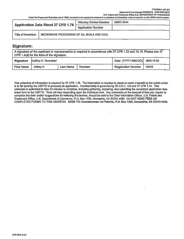
[0087] FIG. 1A
illustrates an elevation view of the beginning section of a tire cuttings
plant layout according to an aspect of the present invention. This illustration
shows two tire processing lines side-by-side in a parallel configuration. Tires
from automobiles and trucks are first cut into suitable chips, e.g., 4 x 4 or 5
x 5 chips (not shown). The tire chips are transported using incline belt
conveyor 120 to accumulation silos 102. The tire chips are then conveyed from
the accumulation silos 102 to a pre-washer screw wash section 122. Tire chips
are then conveyed to a pressure washer hot water sonic washer 105. Dirt, stones,
gravel and other debris is cleaned off of the tire chips to minimize
contamination of the process further downstream. The tire chips are then dried
using forced air dryer system 106. FIG. 1B is a
plan view of the beginning section of a tire cuttings plant layout corresponding
to FIG. 1A.
Cleaned and dried tire chips are then conveyed up another conveyor 120,
as set forth in FIGs. 1C and
1D,
below.
[0088] FIG. 1C
is an elevation view of the midsection of the tire cuttings plant layout
described here. Cleaned and dried chips are transported to accumulation silo
112, which are then transported along transport conveyor 120 to microwave room
124. The details of the microwave room 124 or further described in FIG. 1G
below. In this elevation view, a dual wall tank with enclosed high
high-capacity heat exchanger 118 is shown in dotted lines_ This high- capacity
heat exchanger receives hydrocarbon vapor produced by the microwave
reactors
28
residing within the microwave room 124.
The position of the dual wall tank with enclosed high- capacity heat exchanger 118 is
illustrated further in FIG.
1D.
[0089]
FIG. ID is a plan view of the midsection of the tire cuttings plant
layout described here. Accumulation silos 112 feed tire chips via incline belt
conveyor 120 and screw feed in-feed section 117 to a series of microwave
reactors within hermetically sealed reactor room 116 with filtration system and
vacuum pumps. Tire chips in the screw feed in-feed section 117 are fed into a
first microwave reactor 150 (see FIG.
1G) residing within the microwave room 116. The microwave room is
depicted in FIG.
11:0 containing two sets of microwave reactors side-by-side. Additional
microwave reactors and additional lines can also be added. Hydrocarbon vapors
generated in the microwave reactors from the irradiated tire chips are collected
out of the top of each of the microwave reactors. The hydrocarbon vapors are
then transported, under vacuum (e.g. at a pressure less than ambient) to heat
exchanger 118. The heat exchanger is capable of further separating hydrocarbon
vapors to oil and high carbon gases by cooling to a liquid or a vapor, depending
on the vaporization temperature of the hydrocarbon vapors.
[0090]
The microwave reactor room 116 is also depicted having refrigeration
equipment 123 for maintaining constant room temperature. Processed tire chips
exit the microwave reactor 154 (Fig.
1G)
by a screw feed discharge section 1 l 5. Processed tire chips exit the
final microwave room hot and are subsequently cooled using cooler 114. The
cooled processed tire chips (below about 110°F) then enter a pregrader grinder
system 113, where processed carbon containing materials are separated from
metallic materials (e.g., metal tire cords). Metal materials are separated using
a suitable magnetic conveyor take away system, as shown in 121 in FIGs.
lE and 1F.
Organic particles (e.g. carbon black) can further be shipped to bulk feed
trucks equipped to handle fine particles, other packaging, as well as rail cars.
The resulting organic particles are composed primarily of carbon. In some
embodiments, the organic particles can be used as electronic activators, as
described herein.
[0091]
FIGs. lE and 1F
illustrate the magnetic conveyor take away system 121 for separating
metal particles from nonmagnetic organic matter. Metal is stored in a metal
storage unit 140 while nonmagnetic organic matter (e.g., carbon particles) is
transported via incline belt conveyor 120 to silo and grinder 130. Carbon
particles prepared according to the processes of the present invention are
suitable for use as electron activators for the microwave processing of heavy
residual refinery oil and other materials (e.g., residual oil from the bottom of
a hydrocarbon distillation apparatus that is traditionally unable to be further
processed). In one embodiment, the tire sidewalls can be separated from the tire
treads. Tire treads typically have a
29
greater
amount of carbon black than the sidewalls. Accordingly, the amount of carbon
black recovered from the treads is greater than that of the sidewalls. In one
aspect, carbon black can be accumulated to form electron activator by processing
the treads. Electron activator that can be further used in processing heavy
viscous oil feedstocks. Also present is a sifter system with grinder return 111
for preparing controlled particle size carbon material. The matter in the silo
and grinder 130 is transported by a pneumatic tube conveyor system 119 and
auxiliary pump 136 toward sifter 132, and then to sorter 134, and finally to a
super sack gantry system 138. The super sack entry system 109 is suitable for
loading and unloading using forklift delivery. Also shown is electrical
enclosure 108 containing control panels, a centrifugal feeder/sorter system 110
for managing fine particles.
[0092] As shown in FIGs. ID and 1G, the
microwave reactor room contains two series of three reactors each (one series is
illustrated in FIG. 1G). Tire pieces enter first reactor 150 via screw feed
infeed section 117. This reactor is the largest reactor of the series. 4 x 4 or
5 x 5 inch tire chips are first exposed to microwaves in the first reactor 150
by operation of the microwave antennas
in the first microwave chamber 160. In this first stage, the tire pieces "pop"
or explode into smaller pieces when exposed to the microwaves. The smaller
pieces are separated through a mesh belt 170, and then transported onto another
transportation mesh belt 172. The mesh is designed to keep the microwaves in the
first reactor from getting through and overheating the tire chips. Typically,
the temperature of the tire chips is maintained at about 465°F or less. The mesh
size in the larger reactor will have an opening of approximately 2 inches, the
mesh size in the midsized reactor is approximately 0.5 inches, and the mesh size
opening for the smallest reactor is approximately 1/16".
[0093] Microwaves are generally generated
outside of the microwave room and transported into the microwave room by a
suitable microwave conduit, e.g. stainless steel wire. The design and
interconnection of the three microwave reactors in series is provided so that
the location of the tire chips in the microwave radiation zone is maintained so
that the tire chips do not exceed 465°F. Initially, "popping" of the tire begins
in the first reactor 150 when the temperature of the tire chips is in the range
of from about 300°F to about 450°F. It has been surprisingly found that once the
temperature exceeds about 450°F, the carbon black residing within the tires can
be charred and overcooked and the efficiency of the process for recovering
hydrocarbon fuel oils diminishes drastically. Accordingly temperature is
desirably maintained below about 465°F, or even below about 550°F. Without being
bound by any particular theory of operation, it appears that the tire chips pop
because the reactors are under vacuum and a lot of gas within the tire chips is
being released suddenly upon irradiation with microwaves.
30
[0094]
Suitable operating pressures are the range of up to about 20 mm of
mercury, or even up to about 40 min of mercury, or even up to about 100 mm of
mercury. Accordingly, tire chips processed in the first microwave reactor 150
are then transported to the second microwave reactor 152, where the processed
chips are further irradiated under vacuum using microwave antennas
162. The tire chips are further reduced in size, and fall through mesh 174, and
then transported to the third microwave reactor 154. In the third microwave
reactor 154, the processed chips are further irradiated using microwave antenna
164. Processed chips are finally transported by a screw feed discharge section
118 and exit the microwave reactors from screw feed discharge section 166, and
through airlock (not shown) and onto conveyor 156.
[0095]
Each of the microwave reactors are fed with microwave conduits
terminating in a suitable cone or nozzle. The first microwave reactor has more
microwave nozzles 160 as it is larger than the other two microwave reactors. The
second microwave reactor is shown with microwave nozzles 162, and the third
microwave reactor is shown with microwave nozzles 164. Each of the microwave
reactors contains vacuum lines 180 to transport the resulting hydrocarbon gases
to the high-capacity heat exchanger 118 (shown in dotted lines). Also shown in
the microwave room 124 are refrigeration equipment 123 to maintain the
temperature of the ambient conditions in the microwave room, and support
structures 158 for supporting the microwave reactors.
[0096]
Suitable microwave ranges for the processing of tire chips includes using
X- band microwave radiation generators (not shown) transmitted via conduit in
tubes at various frequencies to each of the reactors. Microwave frequencies for
tire processing varies from X- band down towards C-Band radiation. X-band is 5.2
to 10.9 GHz; C-band is 3.9 to 6.2 GHz. K- band radiation is also useful in some
embodiments. K-band is 10.9 GHz to 35 GHz, which includes the sub-bands Ku
(15.35 GHz to 17.25 GHz) and Ka (33.0 GHz to 36.0 GHz). Typically separate
microwave antenna tubes are separated in frequency by approximately 0.2
gigahertz. In the embodiment shown in FIG.
1G, a total of approximately 36 microwave antenna tubes are transported
from a microwave source (not shown) to the microwave reactors. The largest
microwave reactor 150 has the greatest number of tubes, for example about 18.
The second microwave reactor 152 has fewer tubes, approximately 12. The third
microwave reactor 154 has the fewest number of tubes, approximately 60. Each of
the tubes are capable of operating at different frequencies, which frequencies
in certain preferred embodiments varies between about 7.0 and 6.4 GHz. The ends
of the microwave antenna from which the microwave radiation
exits into the reactor chambers are fitted with a suitable cone antenna. Each of
the cone antennae emits microwave radiation at a separate frequency, which is
typically about 0.2 GHz
31
different
than the others that irradiate into each of the microwave reactors. Microwaves
are typically fixed in frequency but they may also be capable of being swept in
a varying frequency manner, for example, by using a variable frequency microwave
generator. A number of different frequency combinations are envisioned, for
example each of the cone antennas may be fixed in frequency, vary in frequency,
or any combination thereof. As the tire chips are irradiated, volatile
hydrocarbon vapors are emitted from the tire chips and collected by vacuum
tubing. Hydrocarbon vapors are then transported to a heat exchanger condenser.
Highly volatile gases and vapors that are not conveniently liquefied can be
separately recovered as a high BTU gas product.
[0097] The plant layout described in FIGS.
IA-1G is operated at a product speed (per line) of approximately 30 tires per
minute on average. Hourly production rate is approximately 36000 pounds per hour
or approximately 1300 ft.3
per hour. This is based upon a used automobile tire weight of approximately 20
pounds (9.1 kg). Or alternatively a used truck tire about 40 pounds (18.2 kg).
The shredded tire chip sizes can be in the range of from about 3 to about 5
inches. Average loose density of the chips is approximately 24 pounds per cubic
foot to about 33 pounds per cubic foot. Heat values generated at atmospheric
pressure range from approximately 12,000 BTUs per pound to about 15,000 BTUs per
pound.
[0098] FIG. 2A is an elevation
view, axial direction, of a microwave reactor suitable for processing oil
cuttings according to an aspect of the present invention. Oil cuttings comprise
dirt, rock, water, carbon deposits, and the like, which oil cuttings are
obtained during drilling operations. Drilling operations include drilling from
an oil rig, drilling from a deep-sea oil platform, as well as mining of shale
rock and coal deposits. During drilling, rock that is rich in hydrocarbons is
typically reached prior to hitting a pocket of oil. This hydrocarbon rich rock
is transported up to the surface and can comprise up to 15% oil, and even up to
25% oil. The consistency can also be similar to oil shale. Hydrocarbon rich rock
can be considered hazardous waste and would need to be disposed of properly. It
cannot be sent to a landfill, and accordingly it has traditionally been handled
by combustion. This is particularly a problem on an oil rig in the middle of the
ocean, where it may be forbidden to dump oil drillings comprising greater than
1% hydrocarbon content. Accordingly, the process of the present invention can
also be used to recover hydrocarbons from drill cuttings, thereby permitting the
drill cuttings to be placed back in the environment after the hydrocarbons have
been substantially removed. As used herein the term "substantially removed"
refers to a composition comprising less than 1% by weight hydrocarbon
content. Oil drill cuttings having less than 0.01% by weight hydrocarbon has
been produced using the processes described herein. Accordingly, the methods
suitably provide drill
32
cuttings
that comprise less than 1 percent, or even less than 0.5 percent, or even less
than 0.2 percent, or even less than 0.1 percent, or even less than 0.05 percent,
or even less than 0.02 percent, or even less than 0.01 percent by weight
hydrocarbons based on weight oil cuttings. Suitable oil cuttings enter into the
system through in-feed grinder system 201. Oil cuttings are ground to a suitable
size, then fed into the microwave reactor chamber (vacuum sealed reactor tank
216) via in feed screw 202. The vacuum sealed reactor tank 216 contains a
helical mixer element 203 for mixing and stirring the ground oil cuttings. The
reactor tank is typically filled to about 40% of its total volume. The
microwaves irradiate the contents of the reactor via antennas that are oriented
in an orbital arrangement emanating from the top of the reactor. The microwave
antennas are desirably flexible and irradiate from several slides from the top
the reactor towards the mixing material below. A helical mixer element is turned
using a motor 210. Microwaves emanating from a cone antenna or a plurality of
cone antennas (not shown) irradiate the oil cuttings with suitable microwave
radiation_ Hydrocarbon gases and oil vapor exit towards the top vacuum tubing
towards vacuum pump and collected in a suitable heat exchanger vapor condensing
unit. Hydrocarbon vapor gases produced by the process of irradiating the oil
cuttings with microwaves exit via a vacuum discharge tube (not shown). Residual
geologic material and unreacted carbon deposits settled towards the bottom of
the reactor. The unvaporized matter is discharged from the microwave reactor 216
via screw feed discharge section 204, and exits the system via discharge system
206. Material exiting the system is suitably clean of hydrocarbons so as to be
considered nonhazardous waste. For example, material exiting the reactor can be
returned to the ocean after drilling, or can be returned to the land after
drilling. Also shown is reactor support structure 205 for holding the components
as set forth in the system.
[0099] FIG. 2B illustrates an
elevation view of the microwave reactor of FIG. 2A, longitudinal
direction. Oil cuttings are added to the system as in-feed via an airlock at
201, which oil cuttings are then transported to the reactor 216 via in-feed
screw 202. Depicted in this diagram is conduit 214 for pulling vacuum on the
airlock, and on the vacuum sealed reactor tank 216, using vacuum pumps 207.
Microwave waveguides 212 are shown entering the vacuum sealed reactor tank 216.
Microwaves emanating from a suitable microwave cone antenna radiates the oil
cuttings within the reactor tank. A helical mixer element 203 rotates to mix the
oil cuttings, convey the oil cuttings, and reflects microwaves throughout the
volume of the chamber. After suitable microwave processing at a particular
residence time, the reacted oil cuttings exits the reactor through screw feed
discharge section 204 and exits via a suitable airlock 206 of the discharge
system. Also shown is reactor support structure 205.
33
[0100] FIG. 2C illustrates an elevation
view of the microwave device and control room suitable for generating microwaves
and propagating the same through waveguides. The microwave device and control
room 208 is depicted as comprising an electrical panel and a series of six
individual microwave generators (222, 226, 230, 234, 238, and 242) each
connected to a series of microwave antennas (220, 224, 228, 232, 236, and 240).
The antennas are combined into a combined antenna conduit 212 which exits the
microwave device control room 208 and leads towards the vacuum sealed reactor
tank 216 as shown in FIG. 2B. Suitable microwaves for processing oil drill
cuttings have frequencies in the range of about 11.2 to about 11.8 GHz,
typically about 11.5 GHz. Oil shale can also be processed using the equipment
and processes described herein at a microwave frequency in the range of from
about 10.6 to about 11.2 GHz, and typically about 10.9 GHz. Tar sands can be
appropriately processed using microwaves 4 to about 12 GHz. Tar sands can also
be processed in the K-band, preferably in the Ku band. Anthracite coal deposits
can also be processed in the KU band as well. A vacuum is maintained within the
microwave reactor chamber using suitable vacuum and hydrocarbon vapor
condensation equipment, for example at pressures less than about 100 mm of
mercury, and even at pressures of less than about 40 mm of mercury, or even at
pressures of less than about 20 mm of mercury. Maintaining such low operating
pressures helps to keep the overall process temperatures below about 465°F or
even a temperatures less than about 450°F so as to prevent overheating and
efficient recovery of hydrocarbon vapors. A large proportion of the hydrocarbon
vapors can be condensed into liquid fuel oil at ambient
temperatures.
[0101] The system described in FIGs. 2A-2C can
be suitably adapted and scaled to process oil cuttings at a throughput of up to
about 2 tons per hour to even up to about 10 tons per hour. It should be readily
apparent to the skilled person how to increase the size and power of the
microwave reactor chamber to yield higher throughputs.
[0102] The system described in FIGs. 2A-2C can also be suitably
adapted in scale to process oil shale rock. The processing of oil shale rock
includes irradiating it with suitable microwaves at power sufficient to increase
the temperature of the oil shale rock to within a range of from about 500°C to
about 600°C. Without being bound by any theory of operation, it is believed that
these processing temperatures are considerably hotter than compared to tire
cuttings for the reason that more energy needs to be applied to the rocks to
volatile lies the hydrocarbons. This is in contrast to softer, substantially
higher concentration hydrocarbon, tires that readily absorb the microwave
energy. Suitable shale rocks are broken down into small pieces after being mined
For example, shale rock pieces are suitably smaller than an inch cube, even
smaller than a half inch cube, or even smaller than about 3/8" cube, even
smaller than about a
34
-
half inch
cube, or even smaller than about 1/4" cube. The hydrocarbon content of the oil
shale rock typically comprises hydrocarbons comprising from about C 10 to about
C25, or even from about C14 to about C22. Oil shale rock can contain up to about
5% by weight hydrocarbons, or even up to about 15% by weight hydrocarbons, or
even up to about 25% by weight hydrocarbons. In some cases, shale rock can
contain up to about 70% by weight hydrocarbons.
[0103] FIGs.
3A and 3B depicts several
embodiments of the present invention for recovering petroleum-based materials
and hydrocarbons from oil slurry. FIG. 3A
and 3B are schematic illustrations of two
embodiments of a microwave assisted system for the distillation and recovery of
heavy oil bottoms, e.g., oil slurry, from a distillation plant. FIG. 3A shows the following elements of a
traditional hydrocarbon distillation plant: 302 distillation tower 360 unrefined
inlet into distillation tower; 304 vapor line; 306 natural gas line; 308 gas
separator; 310 pump; 312 LPG line; 314 gasoline lines; 316 jet fuel (kerosene)
line; and 318 inset: close-up view of the liquid vapor contact caps with an a
distillation tower. This distillation system can be modified using the microwave
process of the present invention as follows. An electron activator 320 is added
using an electron activator pump 322 into residual oil 362. Hot residual oil
line (e.g., heavy oil) 362 is pumped into the microwave reactor 330 and atomized
using an atomizer 334. Microwave waveguide antenna 336 is powered from the
microwave room and control system 340, which control system includes microwave
generators 342 and microwave waveguides 344. The microwaves exit the waveguide
antenna 336 at cone nozzles within the microwave reactor so as to radiate the
atomized residual oil above the atomizer 334. Vacuum pumps 350 connected to the
vacuum line 332 maintains pressure of less than about 20 mmHg, or even less than
about 40 mmHg, or even less than about 100 mmHg. The irradiation of the atomized
residual oil gives rise to cracking of the residual heavy oil, which in turn
produces hydrocarbon vapors such as natural gas 352 and heavier hydrocarbon
vapors such as diesel and heating oil 354. In the microwave reactor 330,
residual oil 362 is removed from the bottom of a distillation tower 302,
combined with electron activator 320 and processed by microwave after
atomization. We have discovered that addition of the electron activator to the
residual oil, for example about 2% by weight based on residual oil of carbon
small particles, gives rise to a much faster, more efficient absorption of the
microwaves to yield more efficient cracking of the residual oil. Accordingly,
electron activator made using microwave processing of tire chips as described
supra is useful for making electron activator. Suitable electron activator is
provided as a fine powder, for example of about a hundred mesh, or finer. The
electron activator may be coarser than 100 mesh, depending on the precise
application and handling requirements. Without being limited by any particular
theory of operation, the electron activator enhances the
35
absorption
of microwaves by the residual oil, which gives rise to faster processing and
more efficient processing of the heavy oil. As a result, the electron activator,
which comprises carbon powder particulates, are capable of absorbing microwave
radiation. Solid particles containing residual hydrocarbons, such as electron
activator, result in popping (as in popcorn) when irradiated. Without being
bound by any particular theory of operation, it is believed that the popping
action of the small electron activator particles within the residual oil
enhances the microwave processing of the residual oil. In certain embodiments,
the electron activator functions as a catalyst for effectuating the microwave
cracking process.
[0104]
Suitable microwave radiation frequency ranges from about 8.0 to about 8.8
GHz, or
in the range of from about 8.1 GHz to about 8.7 GHz, or even in the range of
from about 8.2 GHz to about 8.6 GHz, or even in the range of from about 8.3 GHz
to about 8.5 GHz, or even about 8.4 GHz. The microwave reactor contains a series
of microwave cone antennas that radiate the atomized residual oil with
microwaves. These microwave cone antennas can each receive the same or different
microwave frequencies. When the frequencies differ, they typically are separated
by increments of about 0.2 GHz. Ranges of microwave frequencies are typically
useful for processing the atomized residual oil in this manner. Accordingly
multiple microwave antennas 344 receive microwaves generated by a plurality of
microwave generators 342 provided in the microwave control system 340.
Microwaves are transmitted through microwave antennas 344 to the microwave
antenna conduit 336. Microwaves then enters the microwave reactor. Typically the
residual oil 362 is pre-heated to a temperature of about 350°C so that it is
capable of flowing under pressure and atomized. The use of microwaves has been
demonstrated to effectively crack the hydrocarbon chains in the heavy residual
oil. Atomization helps to increase the surface area of the residual oil and
decrease particle size, thereby effectuating absorption of the microwaves and
cracking of the hydrocarbon chains. The residual oil is suitably heated to
temperatures sufficient that can flow under pressure and atomized. Suitable
temperatures are at least about 250°C, or even at least about 300° C, or even at
least about 350° C, or even at least about 400°C, or even at least about 450°C,
or even at least about 500°C. The residual oil may be preheated using any of a
variety of heating methods, for example convection, conduction, or irradiation,
e.g. microwaves. The heavy residual oil chains crack at least several
times.
[0105] Processes according to the present
invention are capable of producing combustible gases. The processes according to
the present invention are also capable of producing at least several different
weights of oils. These oil products range from carbon content of hydrocarbon
chains comprising from 14 carbons up to about 25 carbons. The starting residual
oils comprise hydrocarbon chains having at least 25 carbons or even at least 28
carbons. The
36
hydrocarbons
in the residual oil do not necessarily need to be linear hydrocarbon chains, for
example cyclic and branched hydrocarbons are also envisioned. Instead of
atomization, hot flowing residual oil can be formed into a thin film and
irradiated with microwaves, or can be ejected into a shooting stream and
irradiated with microwaves, or can be broken into droplets under force of
pressure and irradiated with microwaves. Similar related processes give rise to
narrow dimension residual oil droplets. In certain embodiments the products of
microwave radiation within the microwave reactor 330 illustrated in FIG. 3A
can be recycled back to the distillation tower 302 for further
processing.
[0106]
FIG. 3B is a schematic of another embodiment of a microwave assisted
distillation and recovery unit for heavy oil bottoms from a distillation plant.
This embodiment is similar to that described in FIG.
3B, with the exception that this embodiment further includes a reboiler
348 for heating the bottoms coming from distillation tower 302 by a transfer
line 370. The reboiler heats the bottoms which are distilled in vacuum tower
340. Residual oil 346 from the vacuum tower is combined with electron activator
320 using electron activator pump 322 to provide a mixture of residual oil in
electron activator 362. This mixture is then atomized in microwave reactor in
330. The operation of the microwave reactor is similar to that discussed supra
in FIG.
3A.
[0107]
FIG. 4A illustrates an elevation view of a microwave reactor system
suitable for processing shale rock, tar sands, drill cuttings, and the like.
Inlet feed screw 402 is suitable for transporting shale rock and other
hydrocarbon containing cuttings and the like into microwave reaction chamber
412. Helical screw mixing flights 408 are mounted to an axle 406 which is
rotated using a motor. Helical screw mixing flights mix and transport the
material, such as shale rock pieces, in the microwave reaction chamber interior
404. Microwave antennas 410 enter the interior of the microwave reaction chamber
404. The material within the microwave reaction chamber interior is stirred and
irradiated. Vapors are removed using a vacuum recovery system and condensing
unit (not shown). Material depleted of hydrocarbon vapor is discharged through
the exit discharged from feed system 416. Also shown is a support structure
414.
[0108]
FIG. 4B provides a plan view of FIG.
4A, wherein the direction of the material is shown entering the microwave
reaction chamber via onlet feed screw 402 mixing within the microwave reaction
chamber by a helical screw mixing flights 408, and finally exiting via exit
discharge screw feed system 416. FIG. 4C
is an elevation view of the microwave reactor system along the axis 406,
the near end being the exit discharge screw feed system section 416. FIG.
4D
illustrates a suitable microwave device control room, waveguides, and
vacuum pumps suitable for use with the system illustrated in FIG.
4A. FIG. 4E illustrates an optional hopper
37
elevator
for transporting material into the inlet feed section 402. FIGs. 4F and 4G
illustrate three horizontal microwave reactor systems operating in parallel.
FIG. 4H illustrates additional microwave generators, waveguides and vacuum pumps
for operating the three horizontal microwave reactors illustrated in FIGs. 4F
and 4G. The processing of hydrocarbon containing materials, such as shale rock,
tar sands, drill cuttings and the like, is conducted in a vacuum environment,
less than about 20 mm of mercury, or less than about 40 mm of mercury, or even
about less than 100 mm of mercury. The hydrocarbon containing materials are
subject to heating by the microwaves and other heating means, up to about 350°C,
or even up to about 450°C, or even up to about 550°C, or even up to about 600°C.
The hydrocarbon containing materials are removed from the microwave reactor
chamber via a suitable vacuum plumbing system. The hydrocarbons are recovered
using a suitable heat exchange or condensing system (not shown).
[0109]
FIG. 5A depicts an exemplary embodiment of the present invention for
extracting petroleum-based materials, carbon-based materials and
hydrocarbon-based materials in
situ. A probe capable of generating microwave radiation (e.g, cone,
antennae or nozzle) according to the methods of the present invention can be
lowered into drilled oil wells. Using the methods of the present invention, the
petroleum-based materials can be vaporized and collected
at surface-level and processed using techniques known in the art. FIG.
5A illustrates a schematic view of a microwave system for in situ
recovery of oil from geologic deposits. A suitable geologic deposit 526 includes
an oil well, a capped oil well, a shale rock deposit, a tar sand deposit, a coal
deposit, and the like. This illustration depicts a vacuum recovery unit 502
(e.g., a Venturi type system) for recovering geologic hydrocarbons such as
fossil fuels from a capped oil well. This system comprises casing 504 extending
from the surface of the ground to the geologic carbon deposits at 526. A
microwave waveguide is delivered through the casing to the geologic carbon
deposit 526. A microwave antenna nozzle 510 resides at the end of the microwave
waveguide 506 proximate to the geologic carbon deposit, into which microwaves
radiate. On the ground surface is illustrated portable electric generator 522,
portable pumping system 524, and portable microwave generation station control
unit 520. Hydrocarbon vapors generated by the microwaves in the geologic carbon
deposit 526 are transported under vacuum as vaporized geologic carbon deposit
(e.g., oil vapor) 508 to the vacuum recovery unit on the surface ground. Capped
oil wells contain hydrocarbons that can be cracked to oil, suitable for use as
diesel fuel. This involves opening up capped oil wells, optionally adding
electron activator into the wells (which aid in absorbing the microwaves and
converting the heavy oil in the wells to hydrocarbon vapor), and irradiating the
heavy hydrocarbons with microwaves. Once vaporized, the hydrocarbons are readily
transported to the surface using suitable vacuum piping,
38
or other
plumbing means 528. The vacuum recovery unit 502 is also capable of
fractionating the hydrocarbons into other hydrocarbon products. Oils that are
difficult to recover using normal pumping means can be recovered according to
the processes.
[0110] FIG. 5B
depicts an apparatus of the present invention for recovering petroleum-
based materials from oil shale, in
situ. A probe capable of generating microwave radiation according to the
methods of the present invention, can be lowered into oil shale deposits. Using
the methods of the present invention, the petroleum-based materials can be
vaporized and collected at surface level and processed using techniques known in
the art. FIG.
5B illustrates a schematic view of a microwave system for recovering
hydrocarbons below ground. In this embodiment, one or more microwave antennae
are shown capable of traveling horizontally underground with respect to the
ground surface. The microwave antennae are illustrated comprising one or more
microwave nozzles for vaporizing hydrocarbon geological deposits in a vacuum
environment. FIG. 5B
illustrates two conduits (on the left portion of the figure), each
containing a plurality of waveguides that terminate it into a suitable microwave
nozzle or cone emitter. Suitable microwave cones emitters are commercially
available. This process is adapted for recovering residual oil in capped oil
wells, and can also be adapted to other geological hydrocarbon deposits such as
tar sands and shale rock. If the oil well is "dry" with mainly heavy viscous
hydrocarbon material remaining in the well, a microwave antenna is transported
down into the oil well and the antenna-end can reside in one or more of the
openings. Microwave radiation is directed towards the geologic material in the
vicinity of the antenna.
[0111]
Various hydrocarbon geological deposits can be processed underground
using this technology at various depths. Piping for the wells can start at a
diameter of about 24 inches at the surface, which diameter is progressively
narrower and narrower as sections of piping are added as the depth increases. At
a depth of approximately 3000 feet, a typical opening (diameter) of the piping
is about 6 inches. For example oil shale deposits in the Western part of the
United States are relatively shallow, i.e., near the surface. Strip mines are
also relatively shallow, and other deposits may be as deep as 2000 feet or more.
Previously pumped oil wells often have chambers of oil that are not readily
accessible but require opening by an additional explosive or drilling operation.
Certain chambers can also be opened by irradiating the sealing rock material
with microwaves. In a laboratory setting, it has been discovered that oil shale
pops and reduces in size when irradiated with microwaves. As the oil shale
releases hydrocarbons (i.e. oil), the oil shale "pops" like popcorn.
Accordingly, directionalizing microwaves within the geological chambers can give
rise to breakdown of the geological formation (i.e. the rocks pop, break apart,
and fall down and fill the cavity). Accordingly, the antennas can be moved
around
39
within
geological formations to aid in recovering hydrocarbon material. In some
embodiments microwave antennas are placed down about 5000 feet or more, and then
are directionalized to travel on the order of approximately 100 yards or so
horizontally.
[0112] Any type of hydrocarbon
material present within the geological formation can be cracked to gas and
recovered at the surface using fractionalization condensation units. For
example, any carbon suitable for use as diesel fuel can be made by irradiating
oil shale. Resulting diesel fuel is suitably used as Cat Diesel Engine Oil.
Sometimes oil wells are drilled using directional drilling technologies.
Suitable directional drilling technologies are capable of bending at a rate of a
degree a foot to create an angle. Accordingly, flexible microwave antennas are
suitable for use in such oils. Accordingly, the process includes uncapping a
capped oil well. This can be accomplished by drilling out a concrete plug used
to cap the well, if present.
[0113] The system can include
a number of auxiliary equipment located on the surface of the ground. Such
equipment includes, for example, well drilling equipment, vacuum pump vehicle,
fuel tank vehicles, a generator vehicle, and microwave control vehicle that
includes microwave generators, microwave waveguides, and associated equipment.
The vacuum pump vehicle can contain a vacuum pump that is capable of applying
intermittent vacuum pulse technology to raise hydrocarbon gases to the surface.
The hydrocarbon gases are recovered and collected in a suitable distillation
tower or fractionation tower that is fitted with heat exchanger and condensing
unit. Suitable oil wells and other hydrocarbon geological deposits residing in
the ground are accessed via a tube to provide a sealed system with the vacuum
pump vehicle for producing the vacuum environment needed for recovering a
hydrocarbon vapors. Suitable vacuums include absolute pressures of less than
about 20 mm of mercury, or even less than about 40 min of mercury, or even less
than about 100 mm of mercury. The microwave control vehicle contains suitable
flexible microwave waveguides and generators. Typically the end of the microwave
waveguides (e.g., antennas) are fitted with a suitable microwave cone emitter
(e.g., nozzle). The antennas are placed into the mahogany zone in Earth in situ
and microwaves are used to radiate tar sands, or oil shale, or other hydrocarbon
deposits. The microwaves cause vaporization and gasification of the otherwise
viscous and solid-like hydrocarbon and carbon geological sources within the
ground. One or more antenna fitted with one or more cone emitter devices can be
used.
[0114] Generated hydrocarbon
gases (e.g., take off gases) are transported to a suitable fractionation tower
capable of separating the gas, as illustrated in FIG. 5C. Geological material
such as sand and rock from which hydrocarbons have been removed remain within
the geological formation. In some embodiments, an in situ microwave process is
provided. Other
40
embodiments
do not require in situ microwave irradiation of the geological formation, e.g.,
geological material containing hydrocarbons that are mined and provided via
separate feed mechanism into a suitable microwave reactor. Geological material
such as sand and rock can be substantially totally gasified (i.e., depleted of
hydrocarbons and carbons) according to the processes of the present invention,
which geological material is then returned to the environment substantially free
of hydrocarbons. Finally, fuel and other hydrocarbons recovered from the
geological source can be stored in a suitable tanker vehicle and shipped for
delivery, further processing, and so on. The recovered hydrocarbons may also be
transported by pipeline, rail car, and the like. Optionally, the hydrocarbon
vapor recovered from geological sources may be fractionalized on-site using a
suitable distillation tower, as illustrated in FIG. 5A. The process of operating a
distillation tower is suitably described in FIG.
5C, which illustration shows the separation of crude oil using a
fractionating tower into its component products.
[0115] FIG.
6 depicts one embodiment for extracting petroleum-based materials from
shale and tar sands and oil sands. The tar sands can be loaded into the top of
the apparatus, which can be under reduced pressure. Using gravity and shaking,
the tar sands move through the apparatus while being exposed to microwave
radiation as described herein. Vaporized petroleum-based materials can be
captured and collected in separate vessels and refined using methods known in
the art. After the material has passed through the apparatus, it will be
essentially free of petroleum-based materials. FIG. 6 provides an elevation view of a multiple
microwave reactor system suitable for high volume recovery of petroleum, carbon
and hydrocarbons (e.g. diesel oil) from mined material, e.g., oil shale, oil
sands, coal slag, and tar sands. This system is illustrated having the following
equipment: microwave waveguide 602; microwave antennas 620; vacuum gas line 604;
microwave reactors 606 - a total of five connected in series; connecting pipe
608 between microwave reactors 606; top airlock 610 adjacent to in-feed of
surface shale and tar sand material; airlock 612 adjacent to discharge of
depleted material; baffles 614 within vertically oriented microwave reactors
606; support structure 630 to support multiple microwave reactors connected in
series and adjacent to source of surface shale and/or tar sands. Mined material
enters the system at airlock in-feed 610, which minimizes the amount of air
entering the system. The system is also fitted with a suitable vacuum gas line
604 to maintain a vacuum environment (vacuum pumping equipment not shown) of up
to about 20 mm of mercury, or even up to about 40 mm of mercury, or even up to
about 100 mm of mercury. Material enters the first microwave reactors 606
adjacent to the airlock, which material is transported along baffles 614 while
being irradiated with microwave radiation through microwave antennas 620 (as
illustrated in the second through fourth
41
microwave
reactors 606). Microwaves irradiate, heat, and crack the hydrocarbons, which
hydrocarbons exit the system via a vacuum gas line 604 (connections between the
microwave reactors 606 in the vacuum gas line 604 not shown). Geological
material leaves the topmost microwave reactor 606 and enters a first connecting
pipe 608, which partially reacted material is transported to a second microwave
reactor 606. The process is repeated and the material is subsequently
transported and irradiated with microwaves as it progresses along the series of
microwave reactors and connecting tubes. The processed material eventually
arrives at the bottom discharge, where it exits the system through an airlock
612.
[0116] Another embodiment of an apparatus of the
present invention is depicted in FIG. 7. FIG.
7 is a schematic view of a microwave reactor chamber and system for
recovering fuel oil from a hydrocarbon-containing source, such as used tires.
The system includes the following equipment and features: nitrogen supply 702 ;
nitrogen regulator 704; nitrogen flow valve 706; nitrogen inlet 708 to microwave
reactor chamber 710 ; microwave reactor chamber 710; infrared thermocouple 712
to measure average temperature over irradiated area ; nitrogen flow meter 714
for infrared thermocouple purge (low flow) ; microwave scattering reflector 716;
motor 718 for microwave scattering reflector 716 ; platform 720 for holding
hydrocarbon containing materials; irradiation area 722; vacuum outlet 724;
vacuum gauge 726; opening 728 to microwave antennae; microwave source 730 (TVT
or magnetron); temperature gauge 732; vapor transfer tube 734; condenser tube
736; cooling coil 740; oil collector 742; valve drain 744; vacuum bypass valve
746; vacuum pump 748; flow meter 750 for TWT nitrogen purge (flow); nitrogen
supply lines 752; exhaust 754; exhaust gas flow meter 756; reactor chamber 758;
reactor chamber door 760.
[0117] FIGs.
8A, 8B and 8C illustrate an
embodiment of the present invention for incorporating a microwave processing
system to process drilling cuttings on an oil drilling platform. FIG. 8A is a plan view of an exemplary oil
platform incorporating a drill cuttings microwave processing unit. A suitable
placement of a microwave processing unit (further illustrated in FIG. 8C) is provided FIG. 8B illustrates an elevation view of the on
platform in FIG. 8A. FIG. 8C illustrates
a vertical and horizontal configurations of the drill cuttings microwave
processing unit suitable for use in the oil platform illustrated in FIG. 8A.
[0118] FIGs. 9A-9C are electron microscope
photographs at 60,000 times magnification of pyrolytic carbon black material
obtained according to Example 3 and using the system illustrated in FIG. 7. The production of this material is
further described in Example 3, below.
42
[0119]
FIGs. 10A-10E illustrate an additional embodiment of a system for
processing materials containing hydrocarbons. Suitable materials include shale
rock, drilling cuttings, tar sands, plastics, polymeric materials, recycled
hydrocarbon-containing materials, refuse, residual oil, slurry oil, hydrocarbon
distillation bottoms, and the like. These figures illustrate the following
equipment and features: 1001 microwave tubes, amplifier and waveguides; reactor
drum 1004; sealed material in-feed 1002 through reactor drum 1004; in-feed screw
1003; rotating discharge screw 1005; control panel 1006; vacuum pumps 1007;
hydraulic drive transmission system 1008 for rotating reactor drum 1004;
shipping container 1009; vacuum release support 1010; drum bearing seal 1012;
roller bearings 1014; vacuum port 1016; microwave waveguides 1018 entering
rotating reactor drum 1004; mixing flight bars 1020 for mixing materials within
the rotating reactor drum 1004; bearings 1022 by which mechanism the drum
slidably rotates; rotating reactor drum axel 1024 by which mechanism the reactor
drum rotates through actuation with the hydraulic drive transmission center
1008.
[0120]
FIG. 10A is an elevation view of a rotating drum reactor system. Material
enters the in-feed 1002 via a suitable source, for example a hopper for
receiving chips or chunks of material. The material then enters into the in-feed
screw 1003, which meters the material into reactor drum I 004. The material is
stirred and mixed using mixing flight bars 1020. The drum is rotated using the
hydraulic drive system 1008. The drum reactor is maintained under vacuum by
means of vacuum pumps 1007 and vacuum gas line. The reactor drum is vacuum
sealed by means of a drum bearing seal 1012 as shown in the inset of FIG.
10D. Microwaves are generated at 1001 and transmitted by a waveguides
1018 into the drum reactor 1004. Hydrocarbon vapors are removed through the
vacuum gas line and collected for further processing as described herein
above.
[0121]
FIG. 10B is a plan view of the rotating drum reactor portion depicted in
FIG.
10A.
The rotating drum 1004 is shown comprising a drum bearing seal 1012,
which drum slidably rotates against end caps comprising ports for microwave
antenna and vacuum connections. The reactor drum slides via roller bearings 1014
in the top and bottom end caps. The drum reactor 1004 resides within shipping
container 1009. Screw conveyor 1003 conveys material into the drum reactor 1004.
FIG.
10C is a plan view of an alternative embodiment of a rotating drum
reactor system. FIG.
10D is a cross-sectional view of a drum bearing seal used in the rotating
drum reactor system.
[0122]
FIG. 10E is an elevation view of the rotating drum reactor portion
depicted in FIG.
10A. FIG. 10E further illustrates the in-feed screw 1003 for metering the
material into reactor drum 1004, which material is stirred and mixed using
mixing flight bars 1020 as the
43
drum is
rotated using the hydraulic drive system 1008. The drum reactor is maintained
under vacuum by means of vacuum pumps 1007 and vacuum gas line. The reactor drum
is vacuum sealed by means of a drum bearing seal 1012 as shown in the inset of
FIG. 10D.
Microwaves are generated at 1001 and transmitted by waveguides 1018 into
the drum reactor 1004. Mixing flight bars 1020 are used for mixing materials
within the rotating reactor drum 1004. Bearings 1022 are used for slidably
rotating the drum while maintaining the vacuum and microwave antenna
connections. The reactor drum rotates by means of axel 1024 through actuation
with the hydraulic drive transmission center 1008. Hydrocarbon vapors are
removed through the vacuum gas line 1016 and collected for further processing as
described herein above. Spent materials substantially depleted of hydrocarbons
exit to discharge screw 1005.
[0123] As an example, a suitable microwave
rotating reactor drum system for extracting hydrocarbons from materials such as
drill cuttings and fluids can comprise the following equipment:
[0124] A
suitable microwave control center includes a number of hydrocarbon specific
modular microwave generators, high power amplifiers, master controller module,
slave driven power modules, thermal sensors, safety I/O devices for vacuum,
interlocks, and emergency shut down, manifold banked configuration of flexible
waveguides/windows/adapter plates, thermal metrology gear microwave power
measurement instruments and computer control station as per
schedule.
[0125] A
suitable 4'-0" diameter rotating in-feed channel drum unit with vacuum seal
provisions comprises 3/8" stainless steel welded frame construction and bolt on
stainless steel (replaceable) hardened steel troughs driven by a direct coupled,
5-hp NEMA-4 variable speed (VFD driven) indexing servo-motor to transfer metered
product into the feed screw.
[0126] A
suitable 2'-6" diameter x 12'-6" long in-feed screw assembly comprises
heavy-duty stainless steel 2" square tubing frame supporting 3/8" stainless
steel skins with hardened helical screw driven by a direct coupled, 2-hp NEMA-4
variable speed (VFD) servomotor to transfer metered product into the
reactor vessel.
[0127] A
suitable 5'-O" diameter x 3/8" horizontal seamlessly welded stainless steel and
jacketed sub-baric vessel is constructed with internal angular flight bars,
(length varies depending on composition of the intended process to) with two -
24" long x 3/8" stainless steel end cap sections, hardened steel
circum-centerline rack & pinion hydraulic transmission driven by a variable
speed gear-head motor. Includes a maintenance access door, piping as required to
heat vessel jacket, microwave antenna mountings, vacuum port, pressure/flow
meters and gauges as required, power transmission is stainless steel guarded.
Reactor tank and peripheral equipment
44
is
supported by heavy duty stainless steel formed structural channels and heavy
duty external bearing wheels.
[0128] A suitable 2'-6" diameter x 12'-6" long
discharge screw assembly comprises heavy-duty stainless steel 2" square tubing
frame supporting 318" stainless steel skins with hardened helical screw driven
by a direct coupled, 2-hp NEMA-4 variable speed (VFD) servomotor to
transfer metered product into the reactor vessel.
[0129] A suitable NEMA 4 electrical motor
control panel, 480v/3ph/60Hz — 24 volt control circuits controls all motors and
devices, directly mounted to shipping container wall, includes Allen-Bradley
PLC, touch screen diagnostics, VFD drive components, I/O racks, rigid conduit
with all marine wire specs, color coded, tagged and match-marked for easy
identification.
[0130] A suitable vacuum system comprises Dual
to Quad (which varies according to throughput) 1.5-hp oil-lubricated, rotary
vane vacuum pumps system for -20in.Hg. continuous duty operation. A vacuum
release port system is mounted on the discharge screw section.
[0131]
Electron activator. It has been discovered that microwave radiation in
the frequency range of from about 4 GHz to about 12 GHz is useful for
selectively recovering hydrocarbon materials from geological petroleum and
mineral sources, as well as manufactured materials such as automobile and truck
tires. It has further been found that such materials can comprise carbon
particles that absorb energy when irradiated with microwave radiation. The heat
from the energized carbon particles is released to the adjacent hydrocarbon
materials, and when sufficient heat is released, the hydrocarbons are reduced in
molecular weight, i.e., "cracked", and vaporized. Unlike the prior art, the
present discovery discloses a particular range of frequencies that is
efficacious for the electromagnetic stimulation and heating of carbon particles
for recovering hydrocarbons, such as diesel fuel, from difficult to recover
hydrocarbon sources.
[0132]
Disclosed are methods for microwave treatment of difficult-to-recover
hydrocarbon source materials comprising contacting the hydrocarbon source
material with particles comprising carbon, and subjecting the hydrocarbon source
material to microwave radiation. Also disclosed are methods for microwave
treatment of hydrocarbon source material comprising contacting the hydrocarbon
source material with material having a resonating frequency in the range of from
about 4 GHz to about 12 GHz, and subjecting the hydrocarbon source material to
microwave radiation characterized as having at least one frequency component
that corresponds to the resonating frequency of the material. As used herein,
carbon particles or material having a resonating frequency corresponding to the
applied microwave radiation frequency arc collectively referred to as "electron
activator".
45
[0133]
In preferred embodiments of the disclosed methods, the microwave
radiation is one or more pre-selected microwave radiation frequencies.
Preferably, the pre-selected microwave radiation frequency will be the
resonating microwave frequency, i.e., the microwave radiation frequency at which
the particles comprising carbon absorb a maximum amount of microwave radiation.
It has been determined that different compositions of the present invention will
absorb more or less microwave radiation, depending on the frequency of the
microwave radiation applied. It has also been determined that the frequency at
which maximum microwave radiation is absorbed differs by composition. By using
methods known in the art, a composition of the present invention can be
subjected to different frequencies of microwave radiation and the relative
amounts of microwave radiation absorbed can be determined. Preferably, the
microwave radiation selected is the frequency that comparatively results in the
greatest amount of microwave radiation absorption. In one embodiment, the
pre-selected microwave radiation frequency is characterized as having at least
one frequency component in the range of from about 4 GHz to about 12 GHz. In
other embodiments, the pre-selected microwave radiation frequency is
characterized as having at least one frequency component in the range of from
about 5 GHz to about 9 GHz, from about 6 GHz to about 8 GHz, or from about 6.5
GHz to about 7.5 GHz.
[0134]
The particles comprising carbon are preferably carbon substances that
have a resonating microwave frequency of from about 4 GHz to about 12 GHz. Many
forms of carbon are known by those skilled in the art, and, while not intending
to exclude other carbon types, it is contemplated that any form of carbon having
a resonating microwave frequency of from about 4 GHz to about 12 GHz will be
within the scope of the present invention. For example, the particles comprising
carbon can comprise carbon black. Carbon black may be described as a mixture of
incompletely-burned hydrocarbons, produced by the partial combustion of natural
gas or fossil fuels.
[0135]
Carbon blacks have chemisorbed oxygen complexes (e.g., carboxylic,
quinonic, lactonic, phenolic groups and others) on their surfaces to varying
degrees depending on the conditions of manufacture. These surface oxygen groups
are collectively referred to as the volatile content. In preferred embodiments,
the present invention uses carbon black having a moderate volatile content. The
volatile content of the preferred carbon black can be composed of hydrocarbons
having up to about 20 carbon atoms, or even up to about 30 carbon
atoms.
[0136]
The constituent parts of the electron activator preferably have
characteristic dimensions in the micrometer range, although other particle or
fragment sizes may also be used. Because carbon particles or particles
comprising another electron activator for use in the present invention can be
present in numerous configurations, and can be irregular in shape, the
term
46
"characteristic
dimensions" is used herein to describe the long axis in the case of
substantially cylindrical or otherwise oblong particles, and to describe
diameter in the case of substantially spherical particles, etc. In some
embodiments wherein the carbon particles comprise carbon black, the particles
can have characteristic dimensions of about 10 nm to about 250 pm. In other
embodiments, the particles can have characteristic dimensions of about 100 nm to
about 100 p.m., or of about 200 nm to about 10 pm.
[0137]
Preferred are electron activators having characteristic dimensions that
are conducive to ready dispersion within hydrocarbon materials that are targeted
for vaporization. The electron activators can be contacted with the hydrocarbon
materials by directly introducing the electron activators into the hydrocarbon
materials environment.
[0138]
In the present systems, the electron activator particles can comprise any
material that is capable of absorbing at least a portion of the transmitted
microwave radiation generated by the microwave generator_ In preferred
embodiments the material comprises carbon. The particles comprising carbon are
preferably carbon substances that have a resonating microwave frequency of from
about 4 GHz to about 12 GHz. Many forms of carbon are known by those skilled in
the art, and, while not intending to exclude other carbon types, it is
contemplated that any form of carbon having a resonating microwave frequency of
from about 4 GHz to about 12 GHz will be within the scope of the present
invention. For example, the particles comprising carbon can comprise carbon
black. Carbon blacks have chemisorbed oxygen complexes (e.g., carboxylic,
quinonic, lactonic, phenolic groups and others) on their surfaces to varying
degrees depending on the conditions of manufacture. These surface oxygen groups
are collectively referred to as the volatile content. In preferred embodiments,
the present invention uses carbon black having a moderate volatile content
prepared by processing tire chips using microwave radiation as described herein
above.
[0139]
The constituent parts of the particles preferably have characteristic
dimensions in the micrometer range, although other particle or fragment sizes
may also be used. Because carbon particles or particles comprising another
electron activator for use in the present invention can be present in numerous
configurations, and can be irregular in shape, the term "characteristic
dimensions" is used herein to describe the long axis in the case of
substantially cylindrical or otherwise oblong particles, and to describe
diameter in the case of substantially spherical particles, etc. In some
embodiments wherein the carbon particles comprise carbon black, the particles
can have characteristic dimensions of about 100 pm.
EXAMPLES
47
[0140] The following examples are provided to
further describe the present invention. They are not to be construed to limit
the scope of the invention described in the claims. Many of the examples make use of the apparatus
substantially illustrated and described in FIG. 7. Example
1
[0141] A chamber capable of
being subjected to between 4.0 to 12.0 GHz of microwave radiation frequencies
and rated to withstand reduced atmospheric pressure, was equipped with a 700 W,
5.8 to 7.0 GHz VFM microwave tube (Lambda Technologies, Morrisville, NC). The
chamber was outfitted with a nitrogen gas inlet tube, a vacuum inlet tube, and
an outlet tube connected to a heat exchanger and collection vessel. The chamber
was also equipped with an infrared thermocouple temperature probe.
Example
2
[0142] A chamber capable of
being subjected to between 4.0 to 12.0 GHz of microwave radiation frequencies
and rated to withstand reduced atmospheric pressure, was equipped with a 1800 W,
7.3 to 8.7 GHz VFM microwave tube (Lambda Technologies, Morrisville, NC). The
chamber was outfitted with an nitrogen gas inlet tube, a vacuum inlet tube, and
an outlet tube connected to a heat exchanger and collection vessel. The chamber
was also equipped with an infrared thermocouple temperature probe.
Example
3
[0143] A 20 lb automobile tire
was cut into approximately 4" x 4" pieces. These pieces were washed and dried.
The pieces were placed on a tray and loaded into the chamber of Example 1.
Twenty psi of N2
was introduced into the chamber. The VFM microwave radiation was
initiated (700 W, 5.8-7.0 GHz). When the temperature of the tire pieces reached
465 °F, the microwave radiation was halted and the tire pieces allowed to cool
about 5-25 F. Microwave radiation was resumed. This process was repeated an
additional three times. Total experiment run time was approximately twelve
minutes. The decomposition products were then analyzed.
[0144] This experiment
produced 1.2 gallons of #4 oil (see Tables 1 and 2), 7.5 lbs of carbon black, 50
cu. ft. of combustible gases (including methane, ethane, propane, butane, and
isobutene), and 2 lbs of steel. FIGS. 9A-9C depict electron
microscope photographs of samples of carbon black produced using this method.
FIG. 9C demonstrates
that the carbon black produced by this method is comparable to commercial-grade
rubber black.
Table 1: Analysis of Oil
Produced by Example 3.
|
TEST
|
RESULT
|
|
Gross
Heat of Combustion
|
18308
BTU/lb
|
|
Gross
Heat of Combustion
|
144688
BTU/gal
|
48
|
Sulfur
|
0.931
wt. %
|
|
Kinematic
Viscosity @ 122 °F
|
9.773
cSt
|
|
Saybolt
Furol Viscosity @ 122 °F
|
78.9
sus
|
|
Sediment
by Extraction
|
0.02
wt. %
|
|
Ash
@ 775 °C
|
0.024
wt. %
|
|
Nitrogen
|
0.43
wt. %
|
Samples
were tested by ITS Caleb Brett, Deer Park, 'IX Samples were filtered through a
100 mesh filter prior to testing.
Table 2: Analysis of Oil
Produced by Example 3
|
TEST
|
RESULT
|
|
Corrected
Flash Point
|
92
°C
|
|
Corrected
Flash Point
|
198
°F
|
|
API
Gravity 15.56 °C, 60 °F
|
13.7
°API
|
Samples
were tested by ITS Caleb Brett, Deer Park, IX
Example
4
[0145] A
sample of oil cuttings, oil shale, tar sands, oil sands, slurry oil, and/or a
material contaminated with petroleum-based materials, is placed in the apparatus
of Example 2. The pressure is reduced to 20 Ton. Microwave radiation is applied
to the sample for a time sufficient to vaporize all the petroleum-based material
in the sample. At 20 Ton, the petroleum- based materials vaporize between about
400 and 520 °F. The vaporized petroleum-based materials are cooled and collected
in a collection vessel. The material remaining in the chamber is substantially
free of petroleum-based material.
Example
5
[0146] A
plastic bottle was placed in the apparatus of Example 1 and exposed to microwave
radiation. The exposure to microwave radiation resulted in complete vaporization
of the bottle and recovery of petroleum-based materials.
[0147] When
ranges are used herein for physical properties, such as molecular weight, or
chemical properties, such as chemical formulae, all combinations, and
subcombinations of ranges for specific embodiments therein are intended to be
included.
[0148] The
disclosures of each patent, patent application, and publication cited or
described in this document are hereby incorporated herein by reference, in its
entirety.
49
[0149] Those
skilled in the art will appreciate that numerous changes and modifications can
be made to the preferred embodiments of the invention and that such changes and
modifications can be made without departing from the spirit of the invention. It
is, therefore, intended
that the appended claims cover all such equivalent variations as fall within the
true spirit and scope of the invention.
50
GBRC-0044
What is Claimed:
1.
A method for obtaining oil or a combustible gas from oil
shale, comprising:
subjecting
oil shale comprising shale rock and kerogen to microwave radiation for a time
sufficient to at least partially decompose said kerogen, wherein
said microwave radiation comprises at least one frequency component in the range
of from about 4 GHz to about 18 GHz; and recovering
oil or a combustible gas from the decomposed kerogen.
2.
The method of claim 1, wherein the oil shale is subjected to
microwave radiation at a pressure
of less than one atmosphere.
3.
The method of claim 2, wherein the oil or a combustible gas is
recovered from the decomposed
kerogen at a pressure of less than one atmosphere.
4.
A method for obtaining a carbon-based material from coal,
comprising:
subjecting
coal to microwave radiation for a time sufficient to at least partially
decompose said coal, wherein the temperature of said coal does not exceed about
700 °F, wherein
said microwave radiation comprises at least one frequency component in the range
of from about 4 GHz to about 18 GHz; and recovering
a carbon-based material from the decomposed coal.
5.
The method of claim 4, wherein the coal is subjected to
microwave radiation at a pressure of less
than one atmosphere.
6. The
method of claim 4, wherein the carbon-based material is recovered from the
decomposed
coal at a pressure of less than one atmosphere.
7.
The method of claim 4, wherein the carbon-based
material is a hydrocarbon.
8.
The method of claim 7, wherein the
hydrocarbon is oil or a combustible gas.
9.
A microwave system for processing coal, oil shale, or both, comprising:
an infeed
airlock configured to receive coal, oil shale, or both, said infeed airlock
being sealable at a pressure less than one atmosphere, wherein said infeed
airlock is configured to gravity feed coal, oil shale, or both into a
microwave reactor coupled to said infeed airlock;
51
GBRC-0044
said
microwave reactor being oriented to permit gravity-driven transport therethrough
of coal, oil shale, or both;
said
microwave reactor further comprising a microwave antenna orientable towards said
coal, oil shale, or both, to irradiate said coal, oil shale, or both while being
transported through the microwave reactor;
said
microwave reactor further comprising a vacuum port to receive carbon- containing
fluid generated from coal, oil shale, or both being irradiated with microwave
radiation characterized as having at least one frequency component in the range
of from about 4 GHz to about 18 GHz;
a
microwave radiation generator operatively coupled to said microwave antenna via
a microwave waveguide, wherein said microwave radiation generator is capable of
generating microwave radiation characterized as having at least one frequency
component in the range of from about 4 GHz to about 18 GHz;
a vacuum
generator operatively coupled to said vacuum port, wherein said vacuum generator
is capable of generating pressure within said microwave reactor below one
atmosphere;
a vessel
or conduit operatively coupled to said vacuum port to receive the carbon-
containing fluid; and
a
discharge airlock operatively coupled to the microwave reactor to receive
microwave-processed coal, microwave-processed oil shale, or both from the
microwave reactor, wherein said discharge airlock is capable of discharging the
microwave- processed coal, the microwave-processed oil shale, or both, from the
microwave system while maintaining pressure within the microwave reactor at less
than one atmosphere.
10. Oil
produced by the method of claim 1.
11. Oil
produced by the method of claim 4.
12. A
combustible gas produced by the method of claim 1.
13. A
combustible gas produced by the method of claim 4.
52
ABSTRACT
The
present invention provides methods and systems for obtaining oil or a
combustible gas from oil shale or coal, by subjecting oil shale or coal to
microwave radiation for a time sufficient to at least partially decompose or
extract oil, gas, or other carbon-containing materials from the oil shale and
coal. The disclosed processes and systems use microwave radiation comprising at
least one frequency component in the range of from about 4 GHz to about 18
GHz.
53
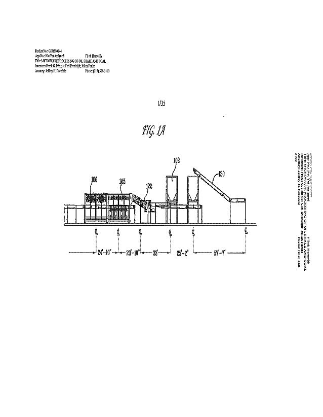
54

55
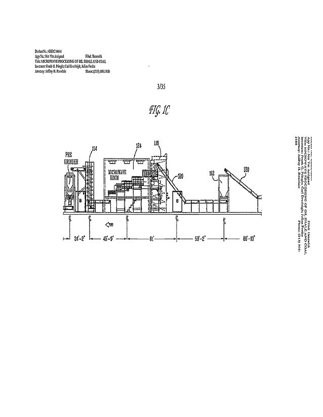
56

57
58
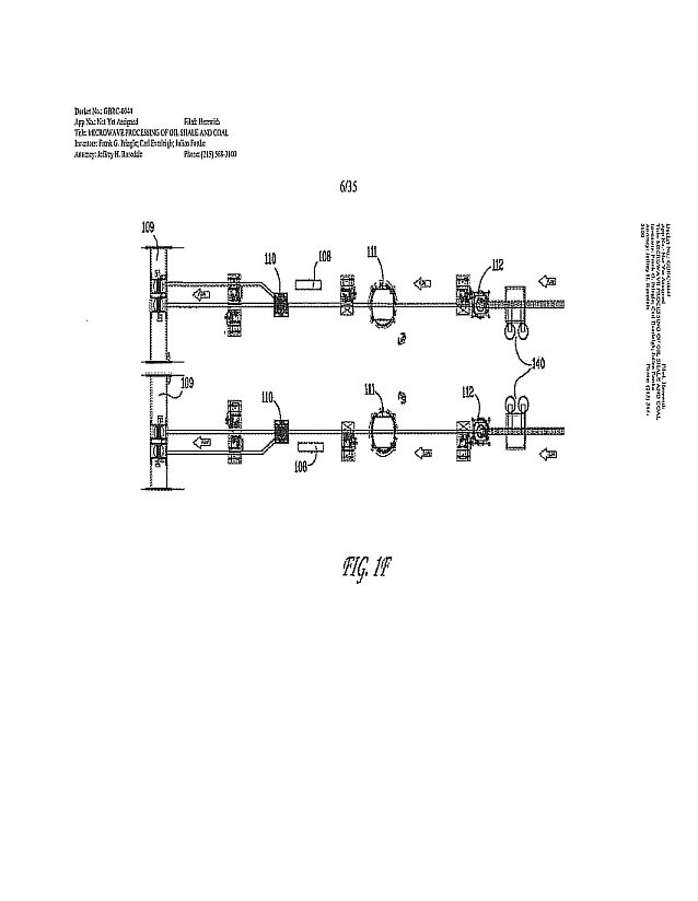
59
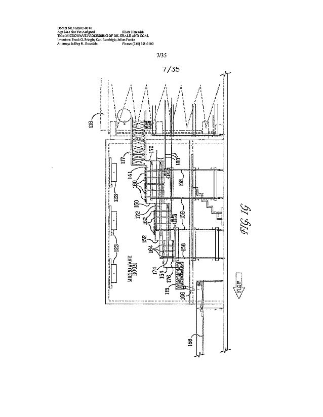
60

61

62
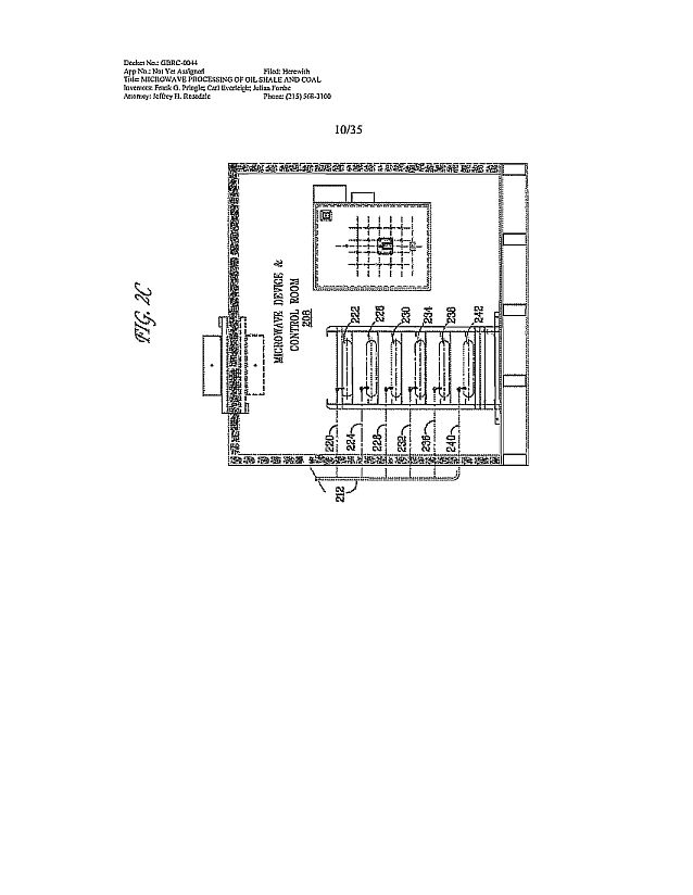
63
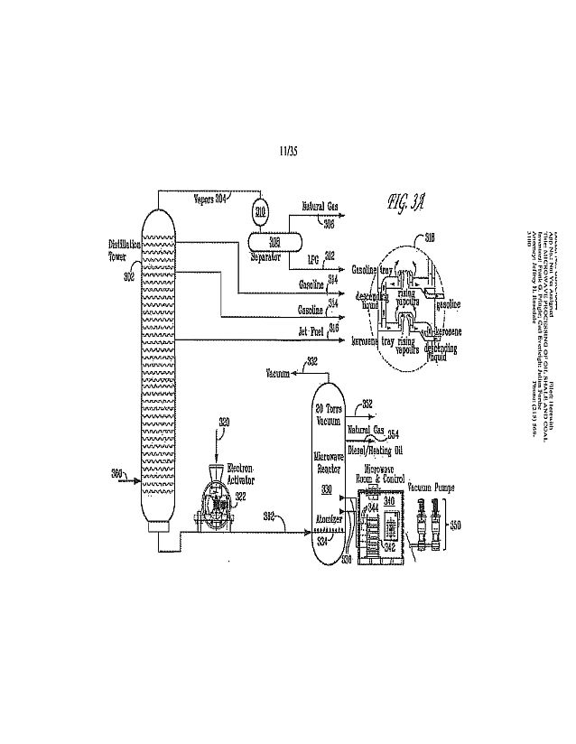
64
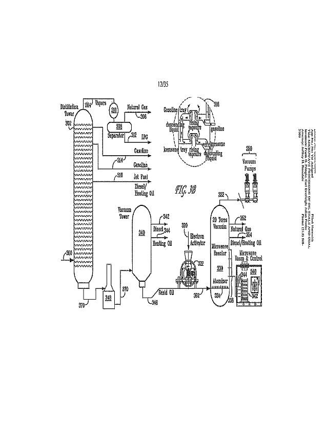
65
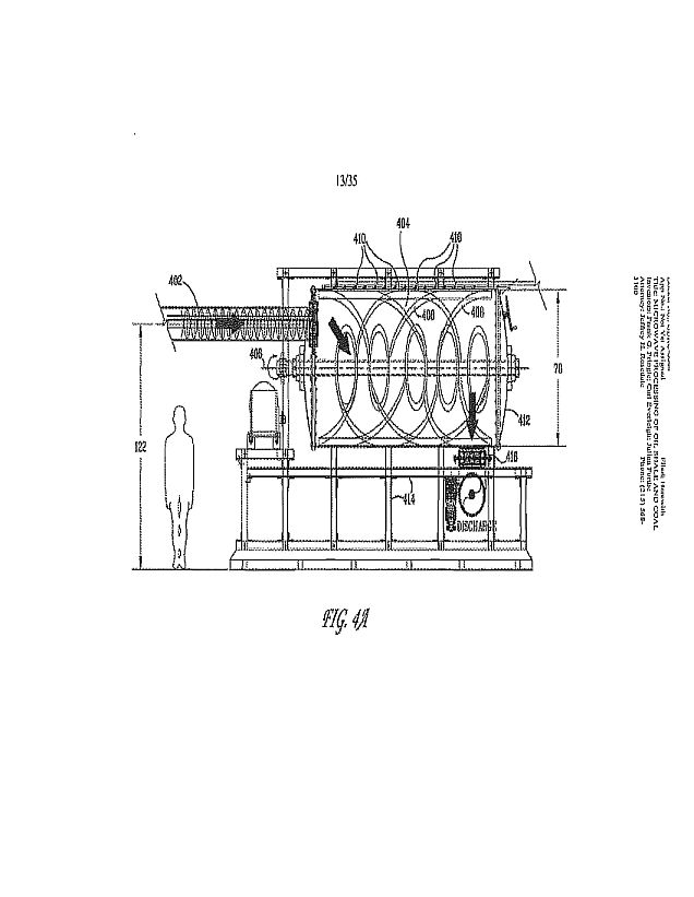
66
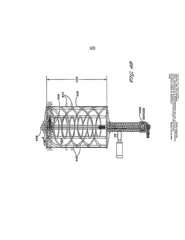
67
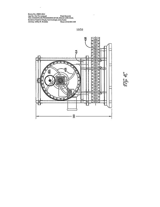
68

69
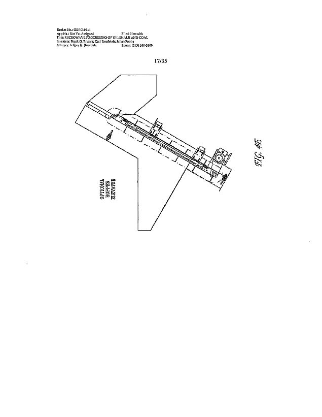
70
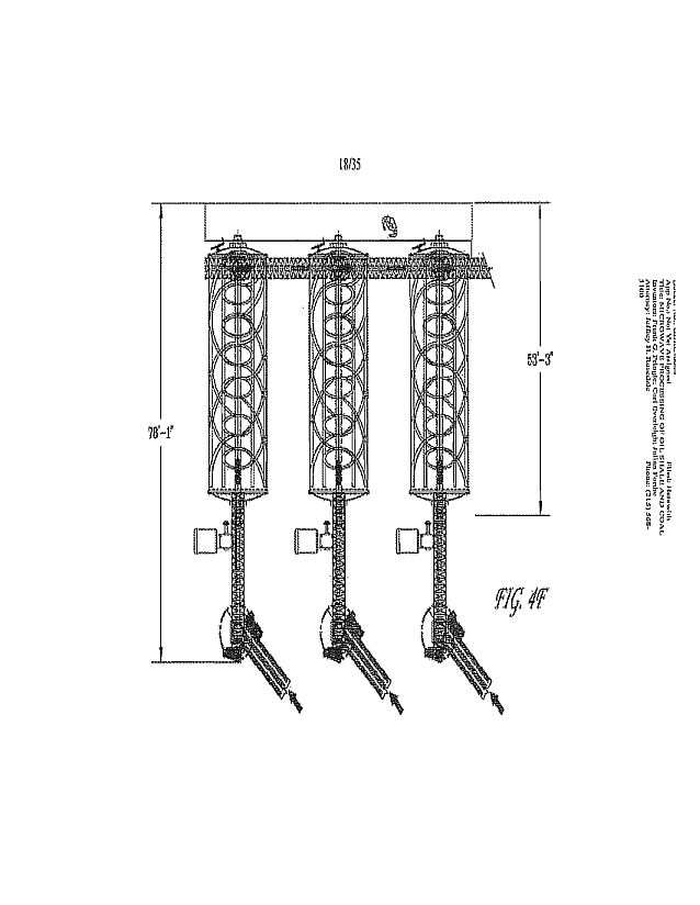
71
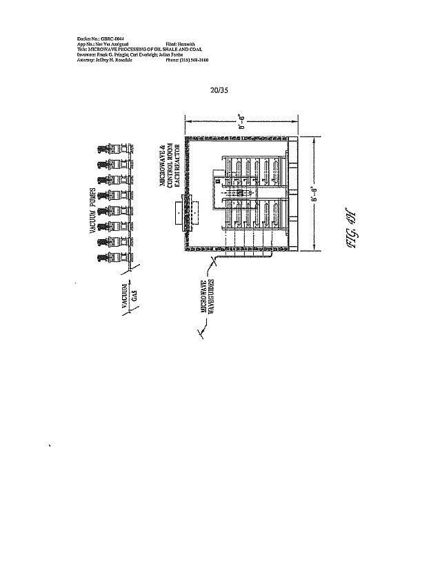
72
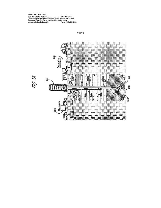
73

74
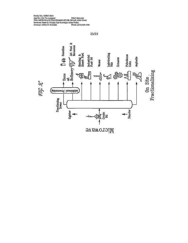
75
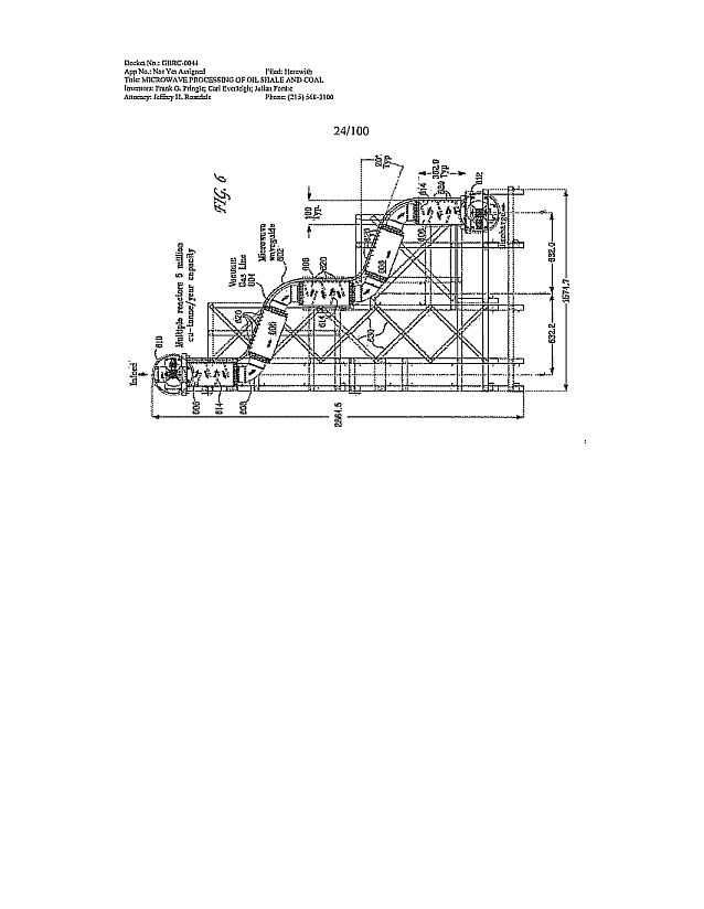
76
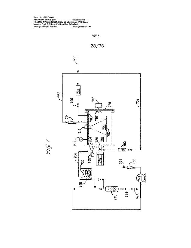
77

78

79

80
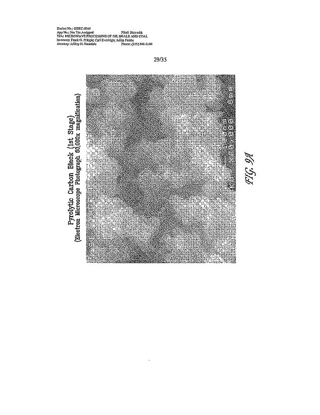
81
82

83

84
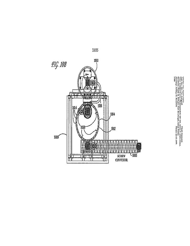
85
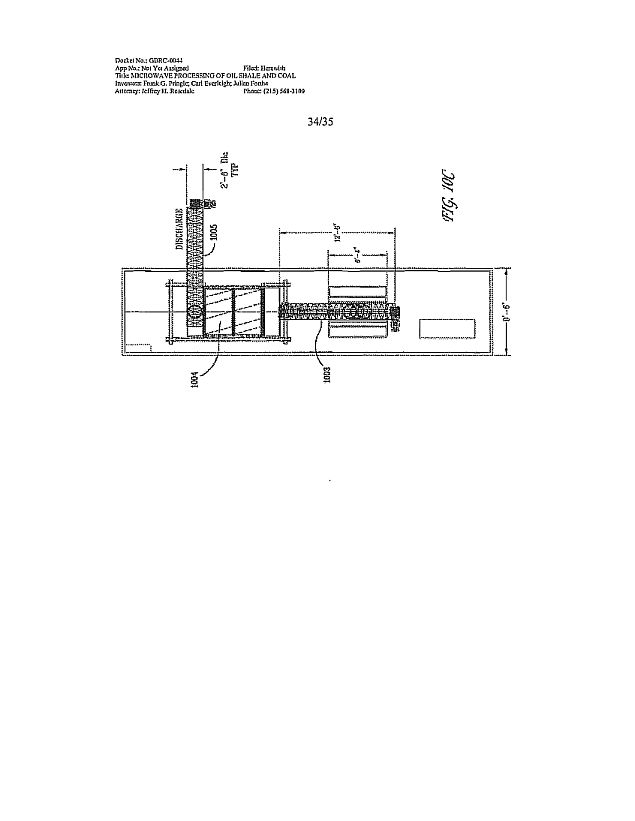
86
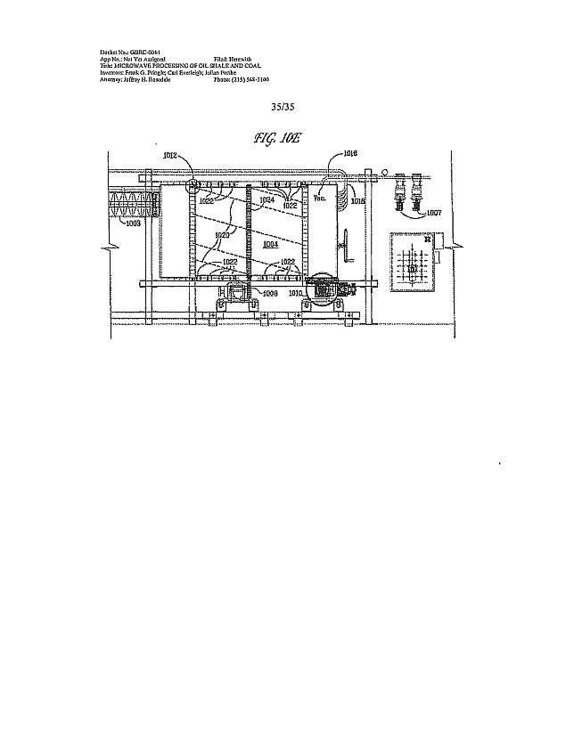
87
|
Electronic
Patent Application Fee Transmittal
|
|||||
|
Application
Number:
|
|||||
|
Filing
Date:
|
|||||
|
Title
of Invention:
|
MICROWAVE
PROCESSING OF OIL SHALE AND COAL
|
||||
|
First
Named Inventor/Applicant Name:
|
Frank
G Pringle
|
||||
|
Filer:
|
Jeffrey
H. Rosedale/Mary Campbell
|
||||
|
Attorney
Docket Number:
|
GBRC-0044
|
||||
|
Filed
as Small Entity
|
|||||
|
Utility
under 35 USC 111(a) Filing Fees
|
|||||
|
Description
|
Fee
Code
|
Quantity
|
Amount
|
Sub-Total
in
USD($)
|
|
|
Basic
Filing:
|
|||||
|
Utility
filing Fee (Electronic filing)
|
4011
|
1
|
82
|
82
|
|
|
Utility
Search Fee
|
211
1
|
1
|
270
|
270
|
|
|
Utility
Examination Fee
|
231
1
|
1
|
110
|
110
|
|
|
Pages:
|
|||||
|
Claims:
|
|||||
|
Miscellaneous-Filing:
|
|||||
|
Petition:
|
|||||
|
Patent-Appeals-and-Interference:
|
|||||
88
|
Description
|
Fee
Code
|
Quantity
|
Amount
|
Sub-Total
in
USD($)
|
|
Post-Allowance-and-Post-Issuance:
|
||||
|
Extension-of-Time:
|
||||
|
Miscellaneous:.
|
||||
|
Total in USD
(5) 462
|
||||
89
|
Electronic
Acknowledgement Receipt
|
|
|
EFS
ID:
|
6194793
|
|
Application
Number:
|
12572715
|
|
International
Application Number:
|
|
|
Confirmation
Number:
|
4483
|
|
Title
of Invention:
|
MICROWAVE
PROCESSING OF OIL SHALE AND COAL
|
|
First
Named Inventor/Applicant Name:
|
Frank
G Pringle
|
|
Customer
Number:
|
23377
|
|
Filer:
|
Jeffrey
H. Rosedale/Mary Campbell
|
|
Filer
Authorized By:
|
Jeffrey
H. Rosedale
|
|
Attorney
Docket Number:
|
GEIRC-0044
|
|
Receipt
Date:
|
02-OCT-2009
|
|
Filing
Date:
|
|
|
Time
Stamp:
|
15:59:53
|
|
Application
Type:
|
Utility
under 35 USC 111(a)
|
Payment
information:
|
Submitted
with Payment
|
yes
|
|
Payment
Type
|
Deposit
Account
|
|
Payment
was successfully received in RAM
|
$462
|
|
RAM
confirmation Number
|
1984
|
|
Deposit
Account
|
233050
|
|
Authorized
User
|
|
|
The Director of the USPTO is
hereby a uthorized to charge indicated fees and credit any overpayment as
follows:
Charge any Additional Fees required under 37 C.F.R. Section 1.16 (National
application filing, search, and examination fees)
Charge any Additional Fees required under 37 C.F.R. Section 1.17 (Patent
application and reexamination processing
fees)
|
|
90
|
Charge any Additional Fees required under 37 C.F.R. Section 1.19 (Document
supply fees)
Charge any Additional Fees required under 37 C.F.R. Section 1.20 (Post
Issuance fees)
Charge any Additional Fees required under 37 C.F.R. Section 1.21
(Miscellaneous fees and charges)
|
|||||
|
File
Listing:
|
|||||
|
Document
Number
|
Document
Description
|
File
Name
|
File
Size(Bytes)/
Message
Digest
|
Multi
Part /.zip |
Pages
(if appl.)
|
|
1
|
Transmittal
of New Application
|
transcontinuationappin.PDF
|
1092829
|
no
|
2
|
|
36e99C63110913c55121,56115.14536ca16ra
th417
|
|||||
|
Warnings:
|
|||||
|
Information:
|
|||||
|
2
|
Application
Data Sheet
|
ADS.PDF
|
1757158
|
no
|
5
|
|
d41
th51f7491d7e902m367921fcla77307
v0.19
|
|||||
|
Warnings:
|
|||||
|
Information:
|
|||||
|
3
|
Authorization
for Extension of Time all
replies
|
PDFauthforeotallreplies.PDF
|
56745
|
no
|
1
|
|
9.134EGabefea5&63e5ed62513/567ad5f1
479c
|
|||||
|
Warnings:
|
|||||
|
Information:
|
|||||
|
4
|
PDFapplicationasfiled.PDF
|
309054
|
yes
|
39
|
|
|
e1dibcc/a1371,a717e3ceee97000271157.2t3
inctil
|
|||||
|
Multipart
Description/PDF files in .zip description
|
|||||
|
Document
Description
|
Start
|
End
|
|||
|
Specification
|
1
|
36
|
|||
|
Claims
|
37 •
|
38
|
|||
|
Abstract
|
39
|
39
|
|||
|
Warnings:
|
|||||
|
Information:
|
|||||
|
5
|
Drawings-other
than black and white
line
drawings
|
PDFfiguresasfiled.PDF
|
1527073
|
no
|
35
|
|
76oto9b4262e1atho294b6thbns.mod
nnar
|
|||||
|
Warnings:
|
|||||
|
information:
|
|||||
|
6
|
Fee
Worksheet (PTO-875)
|
fee-info.pdf
|
33268
|
no
|
2
|
|
05a391322a1176491132711
0e9fet1473d9c11511
cd2a
|
|||||
|
Warnings:
|
|||||
91
Information:
|
Total
Files Size (in bytes):
|
4776127
|
This
Acknowledgement Receipt evidences receipt on the noted date by the USPTO of the
indicated documents, characterized by the applicant, and including page counts,
where applicable. It serves as evidence of receipt similar to a Post Card, as
described in MPEP 503.
New Applications Under 35
U.S.C. 111
If
a new application is being filed and the application includes the necessary
components for a filing date (see 37 CFR 1.53(b)-(d) and MPEP 506), a Filing
Receipt (37 CFR 1.54) will be issued in due course and the date shown on this
Acknowledgement Receipt will establish the filing date of the
application.
National Stage of an
International Application under 35 U.S.C. 371
If
a timely submission to enter the national stage of an international application
is compliant with the conditions of 35 U.S.C. 371 and other applicable
requirements a Form PCT/DO1E01903 indicating acceptance of the application as a
national stage submission under 35 U.S.C. 371 will be issued in addition to the
Filing Receipt, in due course.
New International
Application Filed with the USPTO as a Receiving Office
If
a new international application is being filed and the international application
includes the necessary components for an international filing date (see PCT
Article 11 and MPEP 1810), a Notification of the International Application
Number and of the International Filing Date (Form PCT/RO/105) will be issued in
due course, subject to prescriptions concerning national security, and the date
shown on this Acknowledgement Receipt will establish the international filing
date of the application.
92